Masibus 9000U S User manual

Ref No.: m92A/om/101
Issue No.: 15
1 | P a g e
9000 U
INDEX
Specification......................................................................................................2
Configuration.....................................................................................................3
SAFETY AND WARNING..................................................................................3
Installation.........................................................................................................3
Connecting diagram...........................................................................................3
Application.........................................................................................................4
Ordering Code...................................................................................................4
Trouble Shooting...............................................................................................4

Ref No.: m92A/om/101
Issue No.: 15
2 | P a g e
9000 U
•
9000U Series are rugged 4 wire isolator designed to accept custom-built and
wide range of voltage and current input signals.
Signal is then isolated and
converted to standard instrumentation signals, acceptable to commercially off the
shelf (COTS) automation products.
•9000U Series offer a wide range of input / output signal types like mA, mV,
VDC which are factory settable as per customer requirements.
•Built in transmitter power supply (TPS) can drive filed transmitters in case of 4-
20mA DC input signal.
•9000U Series act as signal distributor when used with more number of outputs.
•9000U Series are flexible for DIN rail mounting and easily installable.
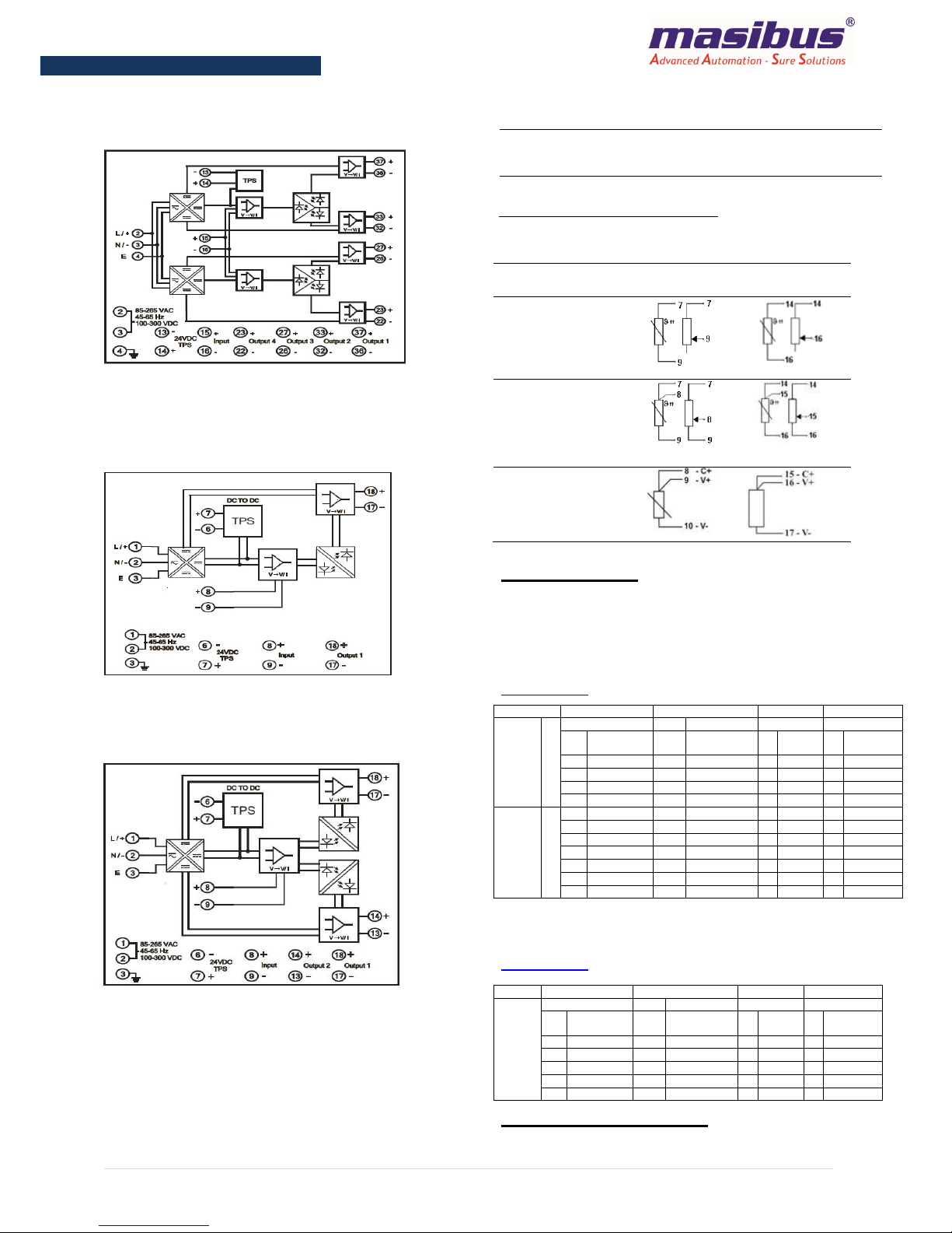
ISOLATED CONVERTER
9000
U SERIES
Three pot Isolation
Mains / DC operated
DIN Rail / Back panel mounted
Built in transmitter powering
Accepts non-std. signal input
option
Up to four isolated outputs of
different types available
D
IMENSION
F
OR
SOP/
DOP
55mm x 75mm x 110mm
85V-265VAC
45-65Hz
100-300VDC
F
OR
TOP/
FOP
100mm x 75mm x 110mm
S
PECIFICATION
Input
Input Type Voltage/ Current/ Potentiometric/ RTD(PT100)
Input Range
For Voltage : Min: 0 to ±10mV, Max: 0 to ±600VDC
For Current : Min: 0 to ±1mA, Max: 0 to ±100mA
For Potentiometric : 0 to 10K Ω
For RTD(PT100): Zero range:-200˚C to 0˚C,
Span range:100˚C to 850˚C
Input Impedance For Current I/
P
< 51 Ω; For Voltage I/P > 1 MΩ
Output
Output Type Voltage/ Current (Reverse range in output is supported with 9000U)
Output Range For Voltage : Min: 0 to ±100mV, Max: 0 to ±10VDC
For Current : Min: 0 to ±1mA, Max: 0 to ±10mA/+20mA
Response Time < 50 ms
Accuracy ± 0.1% of FS / 0.25% of FS in RTD I/P
Output Load resistance
For 0/4mA to 20mA : ≤750 Ω
For -10mA to +10mA : ≤910 Ω
For -1mA to +1mA and 0 to 1mA : ≤9.1K Ω
For 0 to ±1V : ≥200 Ω
For 0 to ±5V : ≥1K Ω
For 0 to ±10V : ≥2.7 KΩ
Auxiliary Output
Transmitter Power Supply 24VDC
Max current Limit: 26mA
Power Supply
Power Supply 85-265VAC 45Hz to 65Hz,100-300VDC / 18-36VDC on request.
Power Consumption Less than 10VA
CMRR >100dB
NMRR >70dB
Isolation Power to Input / Output, Input to Output, Output to Output –
2.0KV AC for 1 minute
Environmental
Operating temperature 0 to 55ºC
Temp. Co-efficient ≤100 PPM
Relative humidity 30 to 95% RH (Non-Condensing)
Protection Conformal Coating on PCB
Physical
Mounting Type DIN RAIL (35 mm) Mounting
Dimensions 55mm x 75mm x 110mm [For SOP/DOP]
100mm x 75mm x 110mm [For TOP/FOP]
Weight
Less than
2
5
0 gm [For SOP/DOP]
,
Less than 450 gm [For TOP/FOP]
Terminal
Terminal Block UL,CSA standard
Terminal Cable Size 2.5mm
2
Isolated Convertor
9000 U Series

Ref No.: m92A/om/101
Issue No.: 15
3 | P a g e
9000 U
C
ONFIGURATION
Front Element of SOP/DOP
Front Element of TOP/FOP
SAFETY
AND
WARNING
To ensure that the device can be operated safely and all
functions can be used, please read these instructions
carefully.
Caution: Never carry out work when the Power
is turned on, this is dangerous.
Installation and startup must be carried out by qualified
personnel only.
The relevant country-specific regulations
(e.g., VDE, DIN) must also be observed.
Before startup it is particularly important to ensure:
• Terminal wiring:
Check that all cables are correctly connected according to
the connection diagram
•
The mains has been connected correctly and protection is
provided against electric shock.
• The device can be switched off outside the power supply
according to EN 60950 regulations (e.g., by the line
protection on the primary side)
• All supply lines should have sufficient fuse protection and
are of correct size.
• All output cables are of correct size for the maximum
device output current or have separate fuse protection.
• Sufficient convection is ensured.
After installation the terminal area must be covered to
provide sufficient protection against unauthorized access
to live parts.
This is ensured by installing the device in the control
cabinet or distributor box.
I
NSTALLATION
Mounting On DIN Rail – 9000U
8 5 V-26 5 V AC
45-65Hz
1 0 0 -3 0 0 VDC
8 5 V-26 5 V AC
4 5 -6 5 Hz
1 0 0 -3 0 0 VDC
8 5 V-2 6 5 VAC
4 5 -6 5 Hz
1 0 0 -3 0 0 VDC
Environment:
Mounting:
The unit can be snapped onto all DIN rails according to
EN 60715. The device must be mounted horizontally
(Input terminal blocks facing downwards)
Installation Dimensions:
To ensure sufficient convection, a minimum
spacing of 3 cm is required.
Place the module with the DIN rail guide way on the
bottom edge of the DIN rail and then snap it downwards.
The housing is mounted on the DIN rail by swiveling it
into place.
As air vents are provided on the top and bottom part of the
unit, the (horizontal) mounting arrangement allows good
vertical air circulation.
Vertical mounting arrangement
of multiple
units must be avoided.
Removal:
Release the snap-on catch using a screwdriver and then
detach the module from the bottom edge of the DIN Rail.
C
ONNECTING DIAGRAM
Item
nos. Details
1,2
Aux. Supply(L,N)
DC+, DC- (In case of
DC Supply)
6,7
24VDC TPS - / +
8, 9
Input + / - (V, mA)
13, 14
Output2 - / + (V, mA)
17, 18
Output1 - / + (V, mA)
21
Power On
RED LED
22
Output1 On
Green LED
23
Output2 On
Green LED
Z
Zero adjustment Pot
for O/P1 and O/P2
S
Span adjustment Pot
for O/P1 and O/P2
Item
nos. Details
2,3
Aux. Supply(L,N)
DC+, DC- (In case of
DC Supply)
13,14
24VDC TPS - / +
15, 16
Input + / - (V, mA)
23, 22
Output4 - / + (V, mA)
27, 26
Output3 - / + (V, mA)
33, 32
Output2 - / + (V, mA)
3
7
, 36
Output1 - / + (V, mA)
39
Power On
RED LED
40
O/P1,O/P2,O/P3,
O/P4
On Green LED
Z
Zero adjustment Pot
for O/P1,O/P2,O/P3,
O/P4
S
Span adjustment Pot
for O/P1,O/P2,O/P3,
O/P4
Caution: Do not install the unit where it is
subjected to continuous vibration.
Do not subject the unit to physical impact.
85V-265VAC
45-65Hz
100-300VDC

Ref No.: m92A/om/101
Issue No.: 15
4 | P a g e
9000 U
Block Diagram and connection details of DOP.
Note: In case of DC supply connect DC(+) to terminal no.
1 and DC(-) to terminal no. 2.
Block Diagram and connection details of TOP/FOP.
Note: In case of DC supply connect DC (+) to terminal no.
2 and DC(-) to terminal no. 3.
Block Diagram and connection details of SOP.
Note: In case of DC supply connect DC(+) to terminal no.
1 and DC(-) to terminal no. 2.
Connecting Cable:
Only operate connectors when the power is switched off.
The following cable cross sections can be connected.
Solid
[mm2] Stranded
[mm2] AWG Torque
[Nm]
[lb in]
Power
Input
Output
0.2
-
2.5
0.2
-
2.5
25
-
14
0.5
–
0.6
4.4 -
5.3
Connection details for Non-Std. Input type:
Connection for Non-
Std. Input type
SOP/DOP TOP/FOP
2 –wire resistance
measurement
(Short terminal 7 & 8
for SOP/DOP and 14
& 15 for TOP/FOP)
3 –wire resistance
measurement
7 & 14 (OPEN)
8 & 15 (WIPER)
9 & 16 (CLOSE)
RTD measurement
8 & 15 (C+)
9 & 16 (V+)
10 & 17 (V-)
A
PPLICATION
•Galvanic isolation, when a mA signal is connected,
to more than one measurement or monitoring
system.
•Conversion of measurement ranges.
•Load amplification and isolation when extra high
load capacity is needed
Ordering Code
9000U
SOP
/DOP
Model Input Type APS No of O/P O/P type
9000U S
X XX X X
C 4-20mA U1 85-265 VAC,
100-300VDC 1 One 1 4-20mA
D 0-20mA U2 18-36 VDC 2 Two
E 1-5VDC
F 0-5VDC
G 0-10VDC
9000U M
X Input Type X
O/P type
C 4-20mA 2 0-20mA
D 0-20mA 3 1-5VDC
E 1-5VDC 4 0-5VDC
F 0-5VDC 5 0-10VDC
G 0-10VDC S Special
S Special
*Note:
Non-Std I/P: Any I/P other than 0-20mA, 4-20mA, 0-5V, 1-5V,
0-10V or Non-Std O/P: Any O/P other than 4-20mA will fall in ‘M’
Category
9000U
TOP
/FOP
Model Input Type APS No of O/P O/P type
9000U
X XX X X
C 4-20mA U1 85-265 VAC,
100-300VDC 3 Three 1 4-20mA
D 0-20mA U2 18-36 VDC 4 Four 2 0-20mA
E 1-5VDC 3 1-5VDC
F 0-5VDC 4 0-5VDC
G 0-10VDC 5 0-10VDC
S Special S Special
T
ROUBLE
S
HOOTING
1. UNIT NOT TURNING ON

Ref No.: m92A/om/101
Issue No.: 15
5 | P a g e
9000 U
The problem can be bad connection / power of incorrect
rating.
First check, power on terminal of the instrument; if it is not
present, then the fault is in power chord.
One must take care while dealing with Power
wirings because it may create electrical shock.
2. UNSTABLE / Vague READING
Check for loose connections.
The reason can be reverse input connections
3. OUTPUT NOT MATCHING WITH THE
EXPECTED VALUE
It is a normal tendency to doubt the instrument performance,
when the Output is not matching the expected value. Kindly
make sure that the output is really incorrect with respect to
input signal, before attempting any re-calibration.
Account for measuring instrument’s inaccuracies, lead errors
and calibration errors. Care must be taken when measuring
Output signal.
Use calibrating instrument of accuracy better than 0.1% for
purpose of calibration. If the signal is still found to be out of
tolerance, calibration should be required.
Masibus Automation and Instrumentation Pvt. Ltd.
B/30, GIDC Electronics Estate, Sector- 25,
Gandhinagar-382044, Gujarat, India
Ph: 91-079-23287275 / 76 / 77 / 78 / 79
Fax: 91-079-23287281/ 82
Web: www.masibus.com
This manual suits for next models
2
Table of contents
Other Masibus Media Converter manuals