General Information
This pure sine wave inverter is designed meet the requirements of a complete off--grid
solar system. It converts DC12V power to AC120V power, the common household
power that charges and operates a wide range of electric appliances, including laptops,
cellphones, digital cameras, fans, music players, air conditioners, and more.
Note: Pure sine wave power is similar to the waveform of grid power. In a pure sine
wave, the voltage rises and falls in a smooth and clean fashion with very low harmonic
distortion, similar to utility power. This results in an inverter that is more stable and
efficient. Only pure sine wave inverters can power sensitive appliances that require a
high-quality waveform with little harmonic distortion, such as refrigerators, washing
machines, microwave ovens, air conditioners, mercury lamps, sodium lamps, and
electric drills.
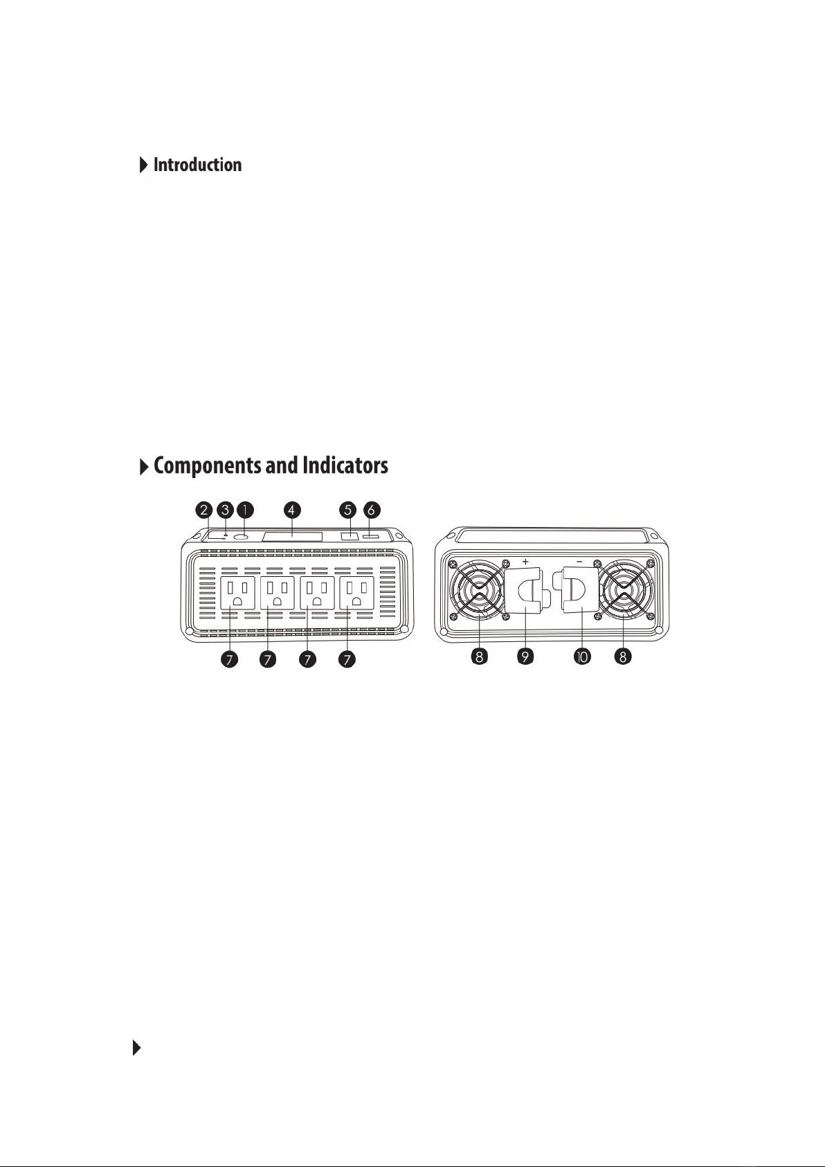
①On/Off Switch
②LED (GREEN): When this green LED is illuminated, the inverter is operating.
③LED (RED): When the red LED is illuminated, the inverter has shut down, due to
overheating, overload, under voltage, or over voltage.
④LCD display
⑤Remote switch connection port: Insert a wired remote switch here (optional).
⑥USB power port: 5V/2.4A for charging tablets, smart phones, and other small
electronic devices.
⑦AC outlets:U.S sockets*4
⑧Fans
⑨Positive terminal
⑩Negative terminal
Inverter Key Features