Massive Dimension MDPE10 User manual

REV. 1 2-16-2021
Massive Dimension
Vermont, USA, Earth
1-802-505-6772
Massive Dimension MDPE10 Extruder
Operation Manual
This manual applies to the Massive Dimension MDPE10.
Triex LLC, Barre, VT 05641, USA

1

2
CAUTION! Read Carefully
●RISK OF ELECTROCUTION Customer is responsible for proper
machine implementation, controls enclosure, grounding, safety
fuses, and wiring. Improper wiring could cause injury or death.
Consult a local electrician if unfamiliar with AC wiring.
●HOT MATERIALS & SURFACES Use gloves and eye protection
while operating the MDPE10 Extruder. The barrel and nozzle are
HOT and melted plastic can stick to the skin and cause serious
burns and injury.
●HIGH-PRESSURE EXPLOSION Air trapped inside the barrel
becomes highly pressurized during operation and can cause small
explosions from the nozzle which eject molten plastic in all
directions.
●TOXIC FUMES Some plastics such as PVC can produce
dangerously toxic fumes when they are heated. Always carefully
review the MSDS of any material before using it in the MDPE10 to
avoid dangers to your health. Always use the MDPE10 in a well-
ventilated area.
●In Case of Emergency ALWAYS include accessible emergency
power shut-offs as part of implementing the MDPE10.
●Only use the MDPE10 to extrude thermoplastic polymers. No other
use has been tested or approved by Massive Dimension.
●Always STOP the extruder before clearing the feed port or removing
the screw. Never stick anything into the feed port while the screw is
turning as this could damage your system.
●The MDPE10 is designed for indoor use only. Operate in a clean, dry
area.
●Only use the specified input voltage to operate the MDPE10 or
damage to the components could occur.
Contact Massive Dimension with any questions
1-802-505-6772
contact@massivedimension.com

3
General Specifications
Thermal Power Input: 208~240VAC-4.8A 50/60Hz 1-Phase
1000W MAX - varies with settings
Weight: 13.8kg (30.5 lbs) - With Servo & Gearbox
7.85kg (17.3 lbs) - Without Servo and Gearbox
Dimensions: 27.8cm D x 20.3cm W x 54.2cm H
(10.9in L x 8.0in W x 21.3in H)
Refer to “MDPE10_Public_Dimensions” for
detailed dimensions. 3D files available on
Massivedimension.com &
Massivedimension.com
Temperature Control: 3 PID Controlled Barrel Heat Zones
(aluminum blocks with dual 150W heaters)
1 PID Controlled Feed Throat Heat Zone
2 24VDC Feed Zone Fans
Max Recommended Run Temp: 660°F (350°C)
Servo Drive: SureServo servo drive 1 kW 230 VAC
1 and 3-phase, (1) RS-232/RS-485/RS-422
(IEEE1394) port Modbus. For use with 750W
and 1 kW servos
Drive Motor: SureServo low inertia AC brushless servo motor
750W, 3-phase input, 2500 lines/10000 ppr
encoder
Gearbox: SureGear high-precision planetary gearbox,
10:1 ratio, inline, 22mm diameter output shaft,
nominal output torque 50 N-m (443 lb-in), 1-
stage, 90mm frame
Final Drive:8mm HTD pitch Timing Belt 20mm wide
22 tooth 22mm bore aluminum pulleys
Screw: Part # EX6-625
16mm (5/8") Diameter
1/2” Pitch
24 L/D Ratio
17-4 PH Stainless Steel Con. H900
2:1 Compression
Nozzle: 1.5mm MD Nozzle (7/8"-14 Thread)

4
Parts Included

5
Parts Included cont.
1. EX6-625 Extrusion Screw 5/8” OD 2:1 Comp
2. Brass Bristle Tube Cleaner
3. Tube Cleaner Extension Rod
4. High-Temperature Resistant Terry Cloth Gloves
5. Copper Gauze
6. Brass Bristle Wheel
7. (4x) MD Nozzle 1.5mm
8. Magnetic Screw Retainer Rod
9. 1-1/8” Mini-change 9-pole cord set 12’ long (AMX10E0010)
10. M12 Female 8-pole shielded thermocouple signal cable 16’ (AMX10E0009)
11. M12 Female 4-pole shielded auxiliary signal cable 16’
12. ZL-SVC-CBL50 ZIPLink servo cable 50-pin connector to 50-pin connector
13. SVC-PFL-020 SureServo power cable 20’
14. SVC-EFL-020 SureServo encoder feedback cable 20’
15. ZL-RTB50 ZIPLink feedthrough module, 50-pole, DIN rail mount
16. SVC-PCCFG-CBL SureServo programming cable 9-pin D-sub 6’
17. SVA-2100 SureServo servo drive, 1 kW, 230 VAC, 1 and 3-phase
18. (4x) SLB4848-V0 SOLO single-loop temperature controller, 1/16 DIN
19. (4x) AD-SSR810-DC-28R Solid state relay 35mm DIN rail mount
20. 2x 1lb Bags of Extruder Purge Compound
Tools Required:
Non-marring bench vice (with V-block) for holding screw while cleaning
Powered Drill with a chuck that can receive a 5/16” or larger shank
3/4” Wrench (for nozzles)
Automotive grade wheel bearing grease (small amount)
Never-Seize/Anti-Seize thread lubricant (450ºC rated or higher)
Recommended:
Compressed air & air blower/duster gun
Heat gun or propane torch
Shop Vacuum Cleaner
Call 1-802-505-6772 or visit massivedimension.com for additional or
replacement parts

6
Thermal Control Components
Refer to “MDPE10 Wiring Diagram” for thermal control wiring
Temperature Control PIDs
Automation Direct Part # SLB4848-V0
Mount these PIDs in a controls enclosure with 1/16 DIN panel cutouts.
Run the auto-tuning function (page 5-2 of the PID manual) at the set
temperature you plan to operate the machine at.
To ensure the PID controllers perform at their highest accuracy, we
recommend re-tuning whenever operating at a temperature more than 30°C
higher or lower than the temperature the previous tune was set at.
PID Manual Link:
https://cdn.automationdirect.com/static/manuals/solobasic/solobasicman
ual.pdf
Temperature Control Relays
Automation Direct Part # AD-SSR810-DC-28R
Mount these relays on a 35mm DIN rail in an enclosure.
Relay Specifications Link:
https://cdn.automationdirect.com/static/specs/ssclass8relays.pdf

7
Servo Motor & Servo Drive Components
Servo Drive
Automation Direct Part # SVA-2100
Refer to the SureServo manual to set up the drive parameters for your
implementation:
https://cdn.automationdirect.com/static/manuals/sureservomanual/surese
rvomanual.html
A serial programming cable is provided (AD Part # SVC-PCCFG-CBL).
Connect the drive to a PC’s 9-pin D-sub serial port to set and load drive
parameters using the SureServo PRO Software which can be downloaded here:
https://support.automationdirect.com/products/sureservo.html
The servo drive I/O is broken out by the ZIPLink feedthrough module (AD
Part # ZL-RTB50). Refer to the ZIPLink manual for pinout details:
https://cdn.automationdirect.com/static/manuals/ziplinks/specsheets/ZL-
RTB50.pdf
Servo Motor
Automation Direct Part # SVL-207
Servo motor manual:
https://cdn.automationdirect.com/static/manuals/sureservomanual/surese
rvomanual.html
Servo Gearbox
Automation Direct Part # PGA090-10A3
Servo gearbox specifications:
https://cdn.automationdirect.com/static/specs/suregearservogb-il.pdf

8
Installing the Screw
1. Apply a very thin layer of grease to all 5 flat surfaces of the square
tang on the back of the screw. Be careful not to leave excess grease
on the edges of the tang to minimize grease getting on the barrel
walls while inserting the screw. Check that there is a thin layer of
grease on the square tang at every screw change.
2. Insert the magnetic screw retainer rod into the small hole near the
feed port on the top of the machine.
3. Insert the screw, square end first, into the end of the barrel. Push the
screw into the barrel until it stops and is retained by the magnet on
the end of the retainer rod. The tip of the screw should be recessed
about 0.44” from the end of the barrel when the screw is fully
inserted. If the screw does not easily insert to the full depth DO NOT
install the nozzle or try to force the screw in. Pull the screw back out
partially, turn it slightly and try again until it seats in the square
coupler.
It should take minimal force to insert the screw fully. DO NOT tap the
screw in as this could jam the screw in the barrel. There could be debris
in the barrel or in the square socket that is stopping the screw. See
“Cleaning” for more information.
CAUTION! The barrel gets HOT! To prevent burns, always use gloves
when working with the screw and nozzles.
4. Apply a thin layer of anti-seize lubricant to the nozzle threads and
screw the nozzle into the end of the barrel. The nozzle should be
snug but not tight, approximately 200 in-lbs (230 kg-cm).

9
Cleaning
Caution! Parts of the extruder get hot! Wear gloves and eye protection!
It is recommended to thoroughly clean the extruder after use, or right
before the next use, for the most consistent extrusion. Polymer melt on
the screw due to heat creep after shutdown can cause issues when
restarting the extruder. Leave the extruder temperature zones on during
cleaning.
1. Either run the extruder until the feed port is empty or use a vacuum
cleaner to remove the remaining pellets. Continue running the
extruder until polymer stops extruding from the nozzle.
2. If you are using a filter nozzle, stop the extruder, remove it, and
replace it with a standard nozzle with a minimum hole size of 1.5mm.
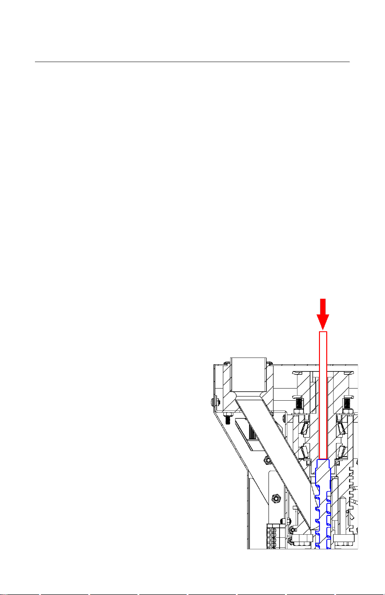
Purge damages the filter. Fill the steel angled feed tube
approximately halfway with extruder purge compound while running
the extruder at approximately 20RPM. Do not change the
temperatures from the polymer that was run to run purge. NOTE:
Use high temp purge for temps over 300°C. It is possible to remove
and clean the screw without using purge material, but the process
can be significantly more difficult and is not recommended.
3. Continue running the extruder until
purge stops extruding from the
nozzle, or add more if the residual
polymer is still visible in the purge.
NOTE: Running the extruder “dry”
with no polymer in the feed will
cause excess wear on the screw
over time. Avoid running the
extruder while empty for more
than a few minutes at a time.
4. After all the purge has been
extruded, stop the extruder and
remove the nozzle.
5. Remove the magnetic screw
retainer rod and insert the tube
cleaner extension rod to push the
screw forward and out from the
end of the barrel.

10
Cleaning - Continued
6. Pull the screw the rest of the way out of the barrel using gloves, then
clamp the back of the screw in a non-marring vice with a v-block for
cleaning. NOTE: Clean the screw while it is still hot.
Always use a smooth, non-marring vice and v-block to secure the
screw. Damage to the screw from the use of an improper vice could
cause wear issues or prevent the screw from fitting in the barrel.
7. Clean the remaining material from the screw using a power drill with
the brass bristle wheel. If present, large pieces of material may need
to be scraped off first. NOTE: Always use soft metal tools (brass,
aluminum, etc.) to remove material from the screw to prevent
marring of the surface which can decrease the life of the screw and
cause extrusion issues. Use a heat gun or propane torch if the screw
cools and cleaning becomes difficult.
8. Screw the brass bristle tube cleaner onto the tube cleaner extension
rod and wrap two layers of copper gauze around the brass bristle
tube cleaner. Wrap the gauze counter-clockwise with the extension
rod pointing toward you.
9. Secure the end of the extension rod in the power drill chuck and
make sure the drill is turning clockwise.
10. Insert the brass bristle tube cleaner into the end of the barrel, while
spinning, and continue until it reaches the feed port. While still
spinning, remove the tube cleaner, and repeat 2~3 times.
11. Use compressed air in the feed tube to blow any remaining debris
out the end of the barrel. Check if the barrel is clean by shining a
light in the feed port and looking into the end of the barrel.
Refer to our online resources at massivedimension.com for cleaning
demos.

11
2021, Triex LLC, Barre VT, USA. No part of this manual may be copied, stored, transmitted, or
otherwise released without the express written consent of Triex LLC. This manual applies only to
the Massive Dimension MDPE10. While Triex LLC has applied all possible caution in producing this
manual, we urge the customer or user of this device to contact Triex LLC with any questions or
concerns about operation, before operating the device or making any adjustments. Triex LLC
provides no assurance of applicability of the product to customers' requirements.
Table of contents
Other Massive Dimension Industrial Equipment manuals