LNWDB1_QSG_EN_R1
HD Video Doorbell
To prepare for installation:
Before beginning setup, there are some essential preparations to
make.
• TURN OFF THE POWER RUNNING TO YOUR EXISTING
DOORBELL AT THE BREAKER.
• Remove your existing doorbell and disconnect wiring.
Microphone
Call button
Speaker
IR LEDs
Camera
PIR sensor
Power ports
Front Panel
Indicator LED strip
Behavior Meaning
Pulsing • Calling
• Resetting
• Hotspot active
Solid Talking
Flashing • Network issues
• Ready for setup
Quick Start Guide
LNWDB1 Series
lorex.com
HD Video Doorbell
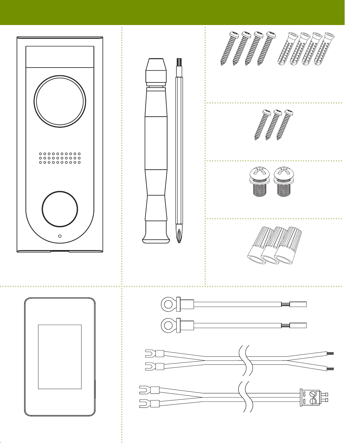
Package Contents
Product Overview STEP 1: Preparation
Back Panel
Need Help?
Visit us online for up-to-date software
and complete instruction manuals
Click on the Downloads tab
4
Visit lorex.com
Search for the model
number of your product
Click on your product
in the search results
3
2
1
Copyright © 2019 Lorex Corporation
As our products are subject to continuous improvement, Lorex reserves the right to
modify product design, specications and prices, without notice and without incurring
any obligation. E&OE. All rights reserved.
Screwdriver
Mounting Screws &
Anchors (×4)
• Read this guide carefully and keep it for future reference.
• Follow all instructions for safe use and handling of the product.
• Use the product within given temperature, humidity and voltage levels noted in the
product’s specications.
• Do not disassemble the camera.
• Do not point the camera directly at the sun or a source of intense light.
• Periodic cleaning may be required. Use a damp cloth only. Do not use any harsh,
chemical-based cleaners.
Safety Precautions
• Not intended for submersion
in water. Installation
in a sheltered location
recommended.
• This camera includes an Auto
Mechanical IR Cut Filter. When
the camera changes between
Day/Night viewing modes, an
audible clicking noise may
be heard from the camera.
This clicking is normal, and
indicates that the camera lter
is working.
• Audio recording without
consent is illegal in certain
jurisdictions. Lorex Corporation
assumes no liability for use
of its products that does not
conform with local laws.
Disclaimers
Chime Kit
Reset button
microSD slot
Wire Caps (×3)
Doorbell & Chime Cables
Door Frame Screws (×3)
TIP: Bend the power cables so they do not fall through the hole in
the wall.
Next, choose one of the following bracket installations based on where you are mounting the doorbell:
STEP 2: Secure the mounting bracket
For installing on brick, stucco, or siding:
For installing on a metal door frame:
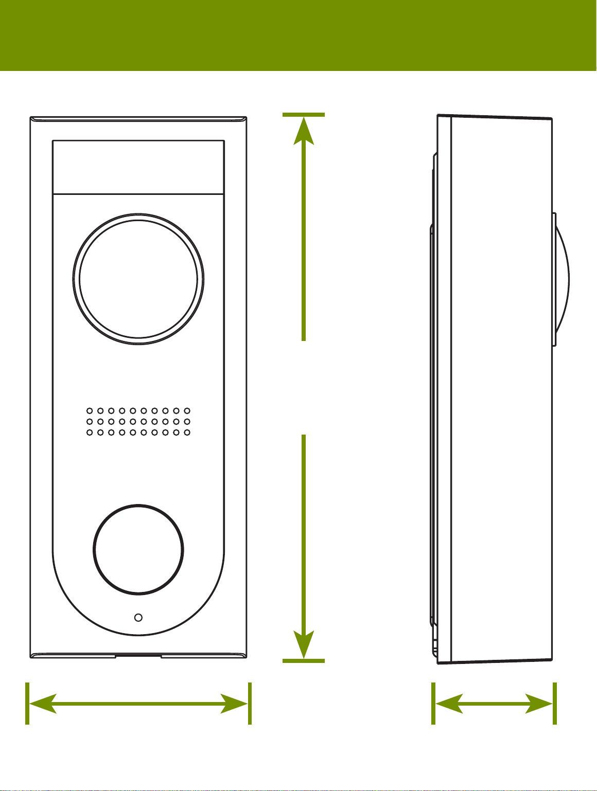
2.4”
60mm
7. 4 ”
187mm
2.4”
60mm
Dimensions
Use the included mounting
screws and plastic anchors
to secure the mounting
bracket to the wall.
Use the included door
frame screws to secure the
mounting bracket to the door
frame.
NOTE
For both installations, ensure the power cables from the wall t
comfortably through the hole in the mounting bracket.
• Remove the metal mounting plate from the back of the doorbell
by removing the pre-inserted security screw on the bottom using
the start end of the included screwdriver.
Power Port Screws (×2)
THIS DEVICE COMPLIES WITH PART 15 OF THE FCC RULES. OPERATION IS SUBJECT TO THE
FOLLOWING TWO CONDITIONS:
(1) THIS DEVICE MAY NOT CAUSE HARMFUL INTERFERENCE, AND
(2) THIS DEVICE MUST ACCEPT ANY INTERFERENCE RECEIVED, INCLUDING INTERFERENCE THAT
MAY CAUSE UNDESIRED OPERATION.
FCC Notice