EVAPCO ATC-E User manual

Rigging and
Assembly nstructions
ATC-E, ATC-ES, ATWB, eco-ATWB and
eco-ATWB-E Evaporative Condensers and
Closed Circuit Coolers
Bulletin ATWB19RIG
Visit EVAPCO’s Website at: evapco.com
EVAPCO...SPECIALISTS IN HEAT TRANSFER PRODUCTS AND SERVICES.
EVAPCO Products are Manufactured Wordwide
EVAPCO, Inc. — World H adquart rs & R s arch/D v lopm nt C nt r
P.O. Box 1300 • Westminster, MD 21158 USA
410-756-2600 p • [email protected] • evapco.com
EVAPCO, Inc.
World H adquart rs
P.O. Box 1300
Westminster, MD 21158 USA
410-756-2600 p | 410-756-6450 f
Asia/Pacific
EVAPCO Asia/Pacific H adquart rs
1159 Luoning Road
Baoshan Industrial Zone
Shanghai 200949, P.R. China
(86) 21-6687-7786 p | (86) 21-6687-7008 f
Europ
EVAPCO Europ BVBA
Europ an H adquart rs
Heersterveldweg 19
Industrieterrein Oost
3700 Tongeren, Belgium
(32) 12-395029 p | (32) 12-238527 f
EVAPCO East
5151 Allendale Lane
Taneytown, MD 21787 USA
410-756-2600 p | 410-756-6450 f
EVAPCO East
Key Building
Taneytown, MD USA
410-756-2600 p
EVAPCO Midw st
Greenup, IL USA
217-923-3431 p
evapcomw@evapcomw.com
EVAPCO W st
Madera, CA USA
559-673-2207 p
EVAPCO Iowa
Lake View, IA USA
712-657-3223 p
EVAPCO Iowa
Sales & Engineering
Medford, MN USA
507-446-8005 p
EVAPCO N wton
Newton, IL USA
618-783-3433 p
evapcomw@evapcomw.com
EVAPCOLD
Greenup, IL USA
217-923-3431 p
evapcomw@evapcomw.com
EVAPCO-BLCT Dry Cooling, Inc.
Bridgewater, NJ 08807 USA
908-379-2665 p
EVAPCO-BLCT Dry Cooling, Inc.
Littleton, CO 80127 USA
908-379-2665 p
EVAPCO Pow r México S. d R.L. d C.V.
Calle Iglesia No. 2, Torre E
Tizapan San Ángel, Del. Álvaro Obregón
Ciudad de México, D. . México 01090
+52 (55) 8421-9260 p
R frig ration V ss ls & Syst ms Corporation
A wholl owned subsidiar of EVAPCO, Inc.
Bryan, TX USA
979-778-0095 p
EvapT ch, Inc.
A wholl owned subsidiar of EVAPCO, Inc.
Lenexa, KS USA
913-322-5165 p
Tow r Compon nts, Inc.
A wholl owned subsidiar of EVAPCO, Inc.
Ramseur, NC USA
336-824-2102 p
EVAPCO Alcoil, Inc.
A wholl owned subsidiar of EVAPCO, Inc.
York, PA USA
717-347-7500 p
EVAPCO Europ , S.r.l.
Milan, Italy
(39) 02-939-9041 p
EVAPCO Europ , S.r.l.
Sondrio, Italy
EVAPCO Europ GmbH
Meerbusch, Germany
(49) 2159 6956 18 p
EVAPCO Air Solutions
A wholl owned subsidiar of EVAPCO, Inc.
Aabybro, Denmark
(45) 9824 4999 p
EVAPCO Air Solutions GmbH
Garbsen, Germany
(49) 5137 93875-0 p
Evap Egypt Engin ring Industri s Co.
A licensed manufacturer of EVAPCO, Inc.
Nasr City, Cairo, Egypt
2 02 24022866/2 02 24044997 p
primacool@link.net / shady@primacool.net
EVAPCO Middl East DMCC
Dubai, United Arab Emirates
+971 4 448 7242 p
EVAPCO S.A. (Pty.) Ltd.
A licensed manufacturer of EVAPCO, Inc.
Isando 1600, Republic of South Africa
(27) 11-392-6630 p
EVAPCO (Shanghai) R frig ration Equipm nt Co., Ltd.
Baoshan Industrial Zone Shanghai, P.R. China
(86) 21-6687-7786 p
B ijing EVAPCO R frig ration Equipm nt Co., Ltd.
Huairou District Beijing, P.R. China
010-6166-7238 p
EVAPCO Air Cooling Syst ms (Jiaxing) Company, Ltd.
Building 10, 1133 Taoyuan Road,
Jiaxing, Zhejiang, China
(86) 573 83119379 p
info@evapcoacs.cn
EVAPCO Australia (Pty.) Ltd.
Riverstone NSW 2765, Australia
(61) 2 9627-3322 p
EvapT ch Asia Pacific Sdn. Bhd
A wholl owned subsidiar of EvapTech, Inc.
Puchong, Selangor, Malaysia
(60-3) 8070-7255 p
North Am rica
South Am rica
EVAPCO Brasil
Equipamentos Industriais Ltda.
Al. Vênus, 151 – CEP: 13347-659
Indaiatuba –São Paulo – Brasil
(55+11) 5681-2000 p
Fan T chnology R sourc s
Cruz das Almas – Indaiatuba
São Paulo, Brasil 13308-200
55 (11) 4025-1670 p
fantr@fantr.com

2
ATC-E, ATC-ES, ATWB, eco-ATWB and eco-ATWB-E Evaporative Condensers and Closed Circuit Coolers
Table of Contents
ntroduction . . . . . . . . . . . . . . . . . . . . . . . . . . . . . . . . . . . . . . . . . . . . . . . . . . . . . . . . . . . . . . . . . . . . . . . . . . . . . . . . . . . . . . . . . . 3
Method of Shipment . . . . . . . . . . . . . . . . . . . . . . . . . . . . . . . . . . . . . . . . . . . . . . . . . . . . . . . . . . . . . . . . . . . . . . . . . . . . . . . . . . . . 3
Structural Steel Support . . . . . . . . . . . . . . . . . . . . . . . . . . . . . . . . . . . . . . . . . . . . . . . . . . . . . . . . . . . . . . . . . . . . . . . . . . . . . . . . 3
Rigging Basin Section . . . . . . . . . . . . . . . . . . . . . . . . . . . . . . . . . . . . . . . . . . . . . . . . . . . . . . . . . . . . . . . . . . . . . . . . . . . . . . . . . . 4
Joining Multi-Cell Units Basin Sections . . . . . . . . . . . . . . . . . . . . . . . . . . . . . . . . . . . . . . . . . . . . . . . . . . . . . . . . . . . . . . . . . . . . 4
Equalizer Blank-Off Plate: Multi Cell Units . . . . . . . . . . . . . . . . . . . . . . . . . . . . . . . . . . . . . . . . . . . . . . . . . . . . . . . . . . . . . . . . . 7
Application of Sealer Tape . . . . . . . . . . . . . . . . . . . . . . . . . . . . . . . . . . . . . . . . . . . . . . . . . . . . . . . . . . . . . . . . . . . . . . . . . . . . . . . 7
Rigging Coil/Fan Section . . . . . . . . . . . . . . . . . . . . . . . . . . . . . . . . . . . . . . . . . . . . . . . . . . . . . . . . . . . . . . . . . . . . . . . . . . . . . . . . 8
Extended Lifts . . . . . . . . . . . . . . . . . . . . . . . . . . . . . . . . . . . . . . . . . . . . . . . . . . . . . . . . . . . . . . . . . . . . . . . . . . . . . . . . . . . . . . . . . 9
Assembly of the Coil/Fan Section to the Basin . . . . . . . . . . . . . . . . . . . . . . . . . . . . . . . . . . . . . . . . . . . . . . . . . . . . . . . . . . . . . . 9
Containerized Unit Assembly . . . . . . . . . . . . . . . . . . . . . . . . . . . . . . . . . . . . . . . . . . . . . . . . . . . . . . . . . . . . . . . . . . . . . . . . . . . 11
Assembly of the Fan Section to the Coil Section (Containerized) . . . . . . . . . . . . . . . . . . . . . . . . . . . . . . . . . . . . . . . . . . . . . 14
Assembly of the Coil Section to the Basin (Containerized) . . . . . . . . . . . . . . . . . . . . . . . . . . . . . . . . . . . . . . . . . . . . . . . . . . . 14
nstalling Watertight Partitions & Firewalls . . . . . . . . . . . . . . . . . . . . . . . . . . . . . . . . . . . . . . . . . . . . . . . . . . . . . . . . . . . . . . . . 15
External Motor nstallation – Belt Drive . . . . . . . . . . . . . . . . . . . . . . . . . . . . . . . . . . . . . . . . . . . . . . . . . . . . . . . . . . . . . . . . . . . 16
Optional Motor & Gear Box Davit nstallation . . . . . . . . . . . . . . . . . . . . . . . . . . . . . . . . . . . . . . . . . . . . . . . . . . . . . . . . . . . . . . 17
Mounting Fan Screens . . . . . . . . . . . . . . . . . . . . . . . . . . . . . . . . . . . . . . . . . . . . . . . . . . . . . . . . . . . . . . . . . . . . . . . . . . . . . . . . . 17
Sloped Ladder nstallation . . . . . . . . . . . . . . . . . . . . . . . . . . . . . . . . . . . . . . . . . . . . . . . . . . . . . . . . . . . . . . . . . . . . . . . . . . . . . 18
External Platform and Vertical Ladder nstallation . . . . . . . . . . . . . . . . . . . . . . . . . . . . . . . . . . . . . . . . . . . . . . . . . . . . . . . . . . 20
Notes . . . . . . . . . . . . . . . . . . . . . . . . . . . . . . . . . . . . . . . . . . . . . . . . . . . . . . . . . . . . . . . . . . . . . . . . . . . . . . . . . . . . . . . . . . . . . . .21
3
ATC-E, ATC-ES, ATWB, eco-ATWB and eco-ATWB-E Evaporative Condensers and Closed Circuit Coolers
Introduct on
This manual provides instructions and recommendations to safely and correctly install all ATC-E, ATC-ES, ATWB, eco-ATWB and eco-
ATWB-E Evaporative Condensers and Closed Circuit Coolers. It is recommended that all the instructions provided in this manual be
reviewed in detail prior to rigging and assembly. If at any point, specific circumstances not covered by this manual arise, please contact
your local EVAPCO representative for assistance.
Proper care must be taken by all parties involved in handling and assembling the equipment to ensure that safe and thorough
installation practices are implemented to prevent damage or injury to the equipment, persons and environment involved.
Method of Sh pment
Induced draft coil products are shipped with the top section(s) separate from the bottom section(s). These sections have mating flanges
and will join together in a waterproof joint when sealed and bolted together as described in the following instructions. Miscellaneous
items, such as sealer, self-tapping screws and any other required materials, are packaged and placed inside the pan for shipment. or
units consisting of multiple cells, drip channels and splash guards will ship loose in the basin for field installation.
or 7' and 8.5' (2.2 m and 2.6m) and 14' and 17' (4.3m and 5.2m) wide units, the motors and drives are factory aligned and then
shipped loose inside the basin section for mounting during installation. Refer to the “External Motor Installation” section in this bulletin.
NOTE: All casing sections are factory inspected prior to shipment to verify proper fit for rigging. Please take extra care to handle and rig
unit section per the instructions of this manual to avoid possible distortion and poor casing alignment. It is advisable to check each
section upon receipt and during each lift to ensure that the factory alignment has not been altered. Should the field inspection indicate the
section alignment (“square”) has been altered, please contact the factory or your local EVAPCO representative for additional instructions
to obtain proper section fit.
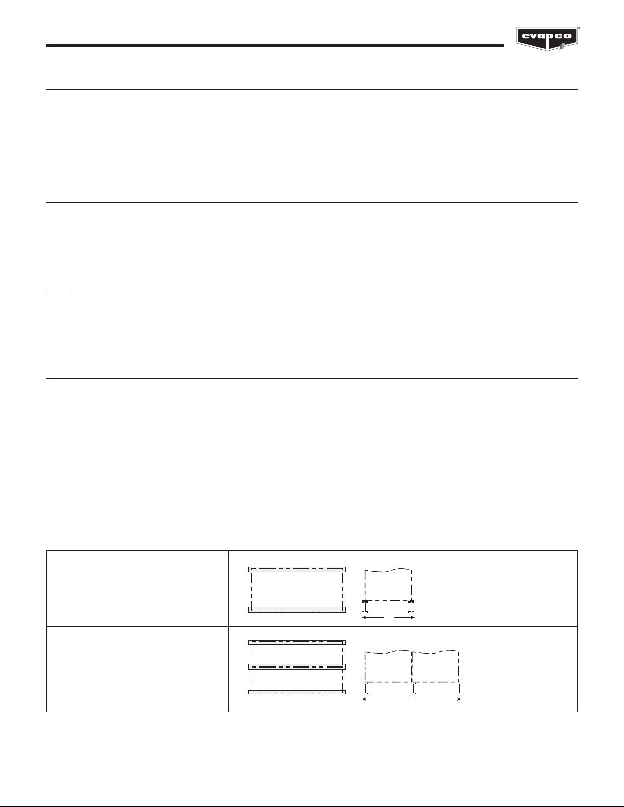
Structural Steel Support
Two structural “I” beams running the length of the unit are required for support of each cell of the units. These beams should be
located underneath the outer flanges of the unit (See Table 1). Mounting holes 3/4” (1.9mm) in diameter are located in the bottom
flanges of the unit for bolting to the structural steel (See steel support print in unit submittal for exact bolt hole location). Bolt the
bottom section to the steel support before rigging the top section.
Beams should be sized in accordance with accepted structural practices. Maximum deflection of the beam under the unit to be
1/360th of the unit length, not to exceed 1/2” (13mm). Deflection may be calculated by using 55% of the operating weight of the
unit as a uniform load on each beam (See certified print in unit submittal for operating weight).
The supporting “I” beams should be level before setting the unit. Do not level the unit by shimming between the bottom flanges
and the beams as this will not provide proper and continuous longitudinal support. Support beams and anchor bolts are to be
furnished by others. Always refer to the certified print in the unit submittal for unit weights, dimensions and technical data.
Please refer to the unit submittal for detailed, project specific steel support arrangement.
W
W
3' (0.914m), 4’ (1.2m), 7’ (2.2m), 8.5’
(2.6m), 10’ (3m), and 12' (3.6m) wide
single & multi-cell units
14’ (4.3m), 16' (4.8m), 17’ (5.2m), 20’
(6m) and 24’ (7.3) wide multi-cell units
Table 1 - Standard Longitudinal Steel Support Arrangement
4
ATC-E, ATC-ES, ATWB, eco-ATWB and eco-ATWB-E Evaporative Condensers and Closed Circuit Coolers
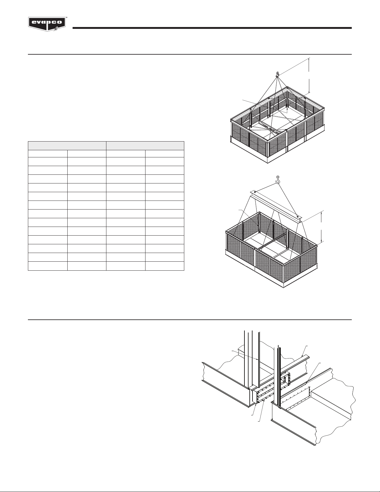
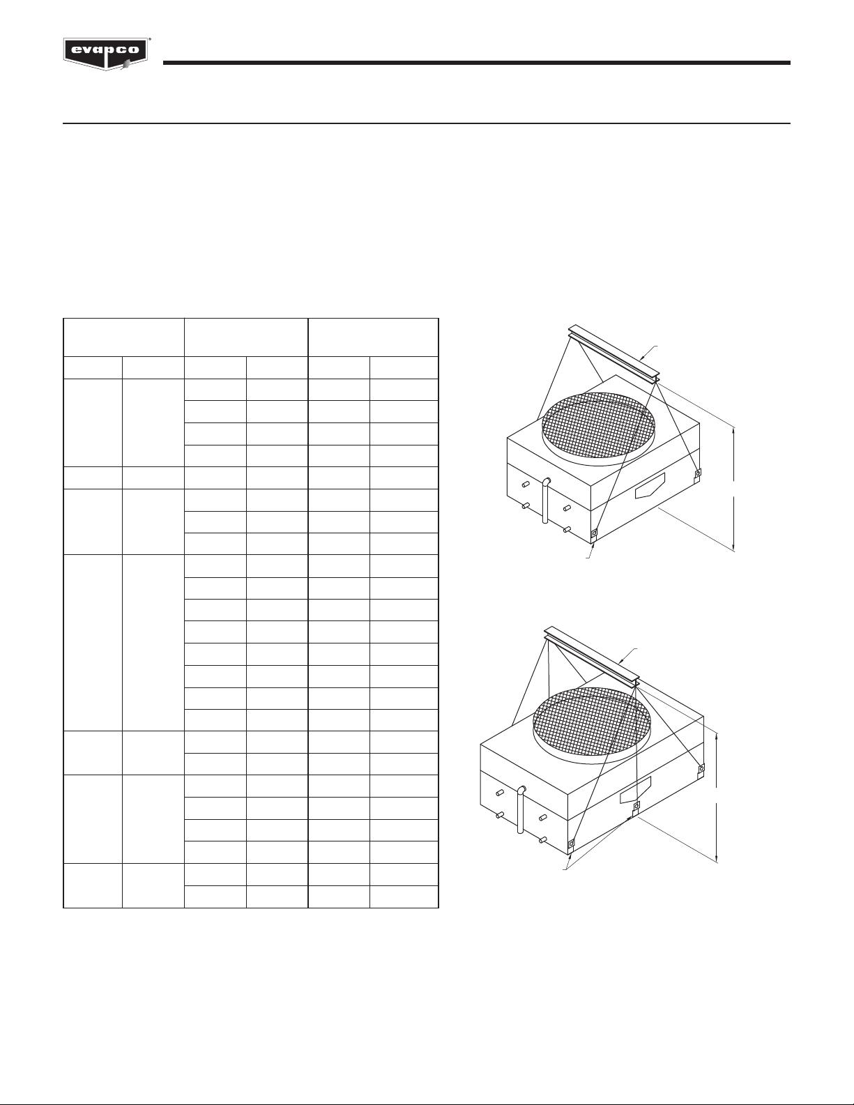
R gg ng Bas n Sect on
Lifting devices are located in the upper corners of the basin
section for lifting and final positioning purposes as shown in
igures 1a and 1b. The hook of the crane must be a minimum
dimension of “H” above the top of the section being lifted to
prevent undue strain on the lifting devices. See Table 2 for the
minimum “H” dimension. These lifting devices should not be
used for extended lifts or where any hazard exists unless
safety slings are employed under the section. (See “Extended
Lifts” section for proper arrangement.) Bolt the basin section to
the steel support before rigging the coil/fan section.
Figure 1b - Basin Section 24' (7.3m) to 40' (12.2m) long
LIFTING
EARS
H
LIFTING
EARS
H
Basin Section Length Min. “H” Dim.
eet Meters eet Meters
3 - 6 0.9-1.8 8 2.4
8.5 2.6 10 3
9 2.7 10 3
10.5 3.2 11 3.4
12 3.6 15 4.6
14 4.3 17 5.2
18 5.5 19 5.8
20 6 21 6.4
21 6.4 22 6.7
24 7.3 15 4.6
28 8.5 16 4.9
36 11 19 5.8
40 12.2 21 6.4
Table 2 - Minimum “H” Dimension for Basin Sections
Figure 1a - Basin Section up to 21' (6.4m) long
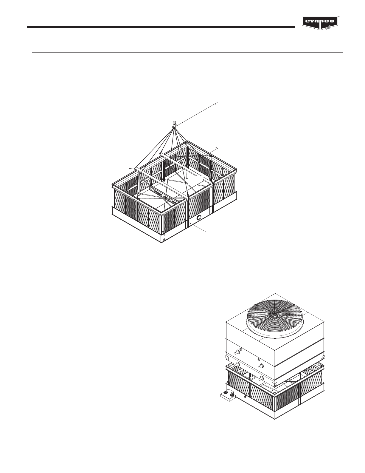
Jo n ng Mult -Cell Un ts
On all 2-cell models, the two bottom sections are shipped
separately and are typically furnished with a connecting equalizer
flume box between them.
In addition to the equalizer flumes, these units are provided with
horizontal drip channels and vertical splash guards to keep water
from splashing out from between the cells. All units have one or
more horizontal drip channel and two vertical splash guards per
flume box. lume boxes are a standard offering on multi-cell units.
The equalizer flume box is factory installed on one section for field
connection to the other. It is important to connect the equalizer
flume to balance the water level in the pans for proper pump
suction operation. The procedures that follow should be
performed in sequence.
HORIZONTAL
DRIP
CHANNEL
VERTICAL
SPLASH
GUARD
FLUME BOX
SEALER
TAPE
RETAINING
CLIP
Figure 2 - Equalizer lume Connection, 12' (3.6m) Wide Models

5
ATC-E, ATC-ES, ATWB, eco-ATWB and eco-ATWB-E Evaporative Condensers and Closed Circuit Coolers
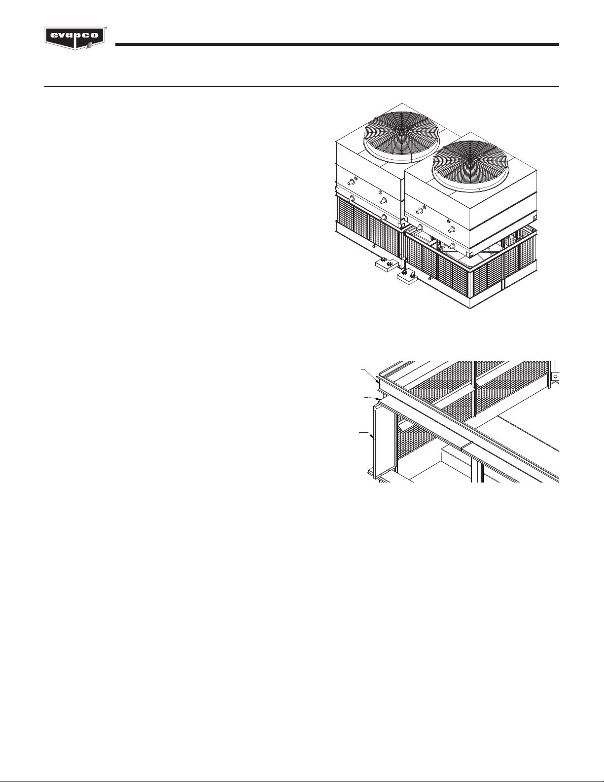
For units on which the flume box ships loose:
1. Rig one of the bottom sections of the multi-cell unit. Bolt to steel support.
2. One face of the flume box is provided with 3/8” (10mm) welded bolts. Clean the mating flume opening on the rigged bottom
section and apply a layer of sealer tape on this surface, centered between the hole centers and the outside edge. Remove
paper backing strip from sealer tape.
3. Align the bolt holes in the rigged bottom section with the welded 3/8” (10mm) bolts on the flume box.
4. Install 3/8” (10mm) nuts and washers on every bolt around the flume opening and tighten.
5. ollow steps 4 through 10 as shown below.
For units on which the flume box ships mounted to one cell:
1. Install the bottom section with the factory installed flume box on it as described above.
2. Clean the flanges on the flume box on the end to be field connected. Apply a layer of sealer tape on the flange, centered
between the hole centers and the outside edge. Remove paper backing strip from the sealer tape.
3. Clean the mating surface of the flume opening of any dirt, grease or moisture.
4. Rig the second bottom section adjacent to the equalizer flume on the steel support as shown in the sequential figures that
follow.
5. Align the bolt holes in the flume box and flume opening with drift pins (by others) while drawing the second bottom section
against the flanged connection.
6. Install 3/8” (10mm) bolts, nuts, and washers in every hole around the flume opening and tighten.
7. Bolt the second bottom section to the steel support.
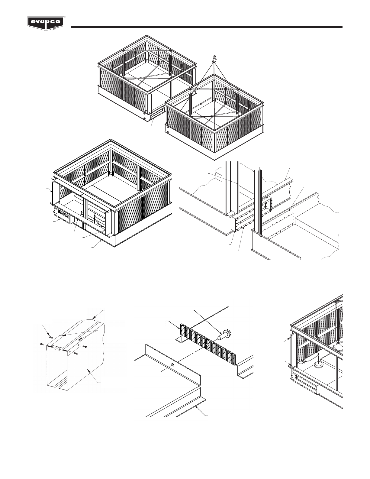
8. Remove the 1/4” (6mm) bolts which hold the drip channel retaining clips to the end panel. Place the drip channel over the
adjoining pan section flanges. Turn around the retaining clips and install them using the same hardware.
9. If there are multiple drip channels, fasten them together end-to-end by driving a self-tapping 5/16” (8mm) screw through the
section end with the larger hole into the mating end with the smaller hole. Stainless steel units will use 5/16” (8mm) stainless
steel nuts and bolts.
10. Place the vertical splash guard in the bend of the vertical supports. On galvanized units, attach the vertical splash guard using
5/16” (8mm) self-tapping screws. On stainless steel units, attach the vertical splash guards using 5/16” (8mm) stainless steel
nuts and bolts. (See figure 3a)
11. Once the bottom of the vertical splash guard has been attached to the drip channel, place the filler cap channel in the upper
flanges of the bottom section as shown in igure 3a. Attach to vertical splash guards using 5/16" (8mm) tappers (for galvanized
units) or stainless steel nuts and bolts (for stainless steel units).
6
ATC-E, ATC-ES, ATWB, eco-ATWB and eco-ATWB-E Evaporative Condensers and Closed Circuit Coolers
FACTORY INSTALLED
EQUALIZER FLUME BOX
VERTICAL
SPLASH
GUARD
FLUME
BOX
DRIP CHANNEL
FILLER CAP
CHANNEL
SIDE PANEL
VERTICAL
SPLASH GUARD
VERTICAL
SPLASH
GUARD
EQUALIZER FLUME BOX
SEALER TAPE
DRIP CHANNEL
RETAINING CLIP
Figure 3a - Drip Channel and Vertical Splash Guard Installation
D IP CHANNEL
SECTION
SEALE TAPE
5/16” (8mm)
TAPPE
DRILLING IS
REQUIRED
IN THE FIELD
FOR THESE
HOLES
DRIP
CHANNEL
RETAINING
CLIP
END PANEL
TAPPERS (GALVANIZED)
OR STAINLESS STEEL
BOLTS (STAINLESS)
Figure 3 - Joining Bottom Sections – Multi Cell Units
7
ATC-E, ATC-ES, ATWB, eco-ATWB and eco-ATWB-E Evaporative Condensers and Closed Circuit Coolers
Equal zer Blank-Off Plate:
Mult Cell Un ts
Equalizer blank-off plate(s) are available to isolate the
bottom sections for individual cell operation, periodic
cleaning, or maintenance.The optional equalizer blank-off
plate is factory installed on the equalizer flume and
secured by wing nuts. This plate is also known as a
“flume plate” or “positive closure plate.”
or units not requiring the blank-off plate under normal
operating conditions, remove the wing nuts, washers,
plate and gasket. Reinstall washers and wing nuts for
proper leak free operation of the equalizer flume box.
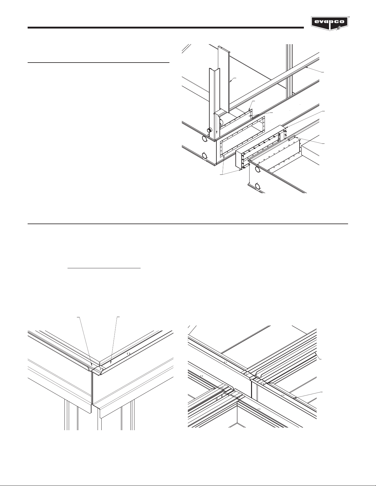
Appl cat on of Sealer Tape
Once the bottom section has been set on the supporting steel and bolted in place, the top flanges should be wiped down to remove
any dirt or moisture. Sealer tape should be placed over the mounting hole centerline on the side flanges along the entire length of
all sides. Apply two strips of sealer tape, one partially overlapping the other, on the entire length of the end flanges (flanges with no
bolt holes).
The sealer tape should overlap on the corners as shown in igure 5a. Do not splice the sealer tape along the end flanges and
preferably not on the side flanges if it can be avoided.
Always remove the paper backing from the sealer tape.
All models with two or more top sections must have sealer tape applied along the entire length of all internal flanges, as shown in
igure 5b.
DRIP
CHANNEL
SEALER TAPE
GASKET
RETAINER
CLIP
FLUME
BOX
BLANK
OFF PLATE
VERTICAL
SPLASH
GUARD
Figure 4 - Equalizer Blank-Off Plate Installation
2 OVERLAPPING LAYERS
OF SEALER TAPE
ON THE ENDS
1 LAYER OF SEALER TAPE
CENTERED OVER THE
MOUNTING HOLES
END SIDE
2 OVERLAPPING
LAYERS
OF SEALER
TAPE ON
THE ENDS
1 LAYER OF
SEALER TAPE
CENTERED
OVER THE
MOUNTING
HOLES
Figure 5b - Sealer Tape Detail for Center Joint of Units with
our Top Sections
Figure 5a - Sealer Tape on lange of Bottom Section
8
ATC-E, ATC-ES, ATWB, eco-ATWB and eco-ATWB-E Evaporative Condensers and Closed Circuit Coolers
R gg ng Co l/Fan Sect on
our lifting ears are provided in the lower corners of most coil/fan sections for lifting into final position. Some 18' (5.5m) long
sections and longer will have two additional lifting ears in the middle of the section. (See igures 6a and 6b.)
Use all lifting ears. A spreader beam must be used for lifting the top section(s) as shown in igures 6a and 6b.
The hook of the crane must be a minimum dimension “H” above the lifting ear to prevent undue strain on the lifting ears. See Table
3 for the minimum “H” dimension. These lifting devices should not be used for extended lifts or where any hazard exists unless
safety slings are employed under the section. (See “Extended Lifts” for proper arrangement.)
Note: or 7' (2.24m) and 8.5' (2.6m) wide models, mount the external motor prior to rigging as detailed in the “External Motor
Installation” section.
Section Section Minimum "H"
Width Length Dimension
eet Meters eet Meters eet Meters
4 1.2 5 1.5
4 1.2 6 1.8 6 1.8
9 2.7 8 2.4
12 3.6 11 3.4
6 1.8 8.5 2.6 9 2.7
9 2.7 9 2.7
7 2.2 12 3.6 10 3
18 5.5 14 4.3
6 1.8 7 2.1
7.5 2.4 8 2.4
9 2.7 9 2.7
8/8.5 2.4/2.6 10.5 3.2 10 3
12 3.6 10 3
14 4.3 12 3.6
18 5.5 14 4.3
21 6.4 17 5.2
10 3 12 3.6 12 3.6
18 5.5 14 4.3
12 3.6 12 3.6
12 3.6 14 4.3 13 4
18 5.5 14 4.3
20 6 15 4.6
14 4.4 24 7.3 17 5.2
26 7.8 22 6.7
Table 3 - Minimum "H" Dimension for Coil/ an Sections
Figure 6a - our Point Lift
SPREADER BEAM
H
LIFTING EARS
SPREADER BEAM
LIFTING EARS
H
Figure 6b - Six Point Lift
9
ATC-E, ATC-ES, ATWB, eco-ATWB and eco-ATWB-E Evaporative Condensers and Closed Circuit Coolers
H
LIFTING
EAR
LIFTING
EAR
SPREADER
BARS
SAFETY SLINGS
Figure 7 - Extended Lifts
Extended L fts
mportant: The lifting devices and “U” bolts should be used for final positioning only and for lifting where no danger
exists. f they are used for extended lifts, safety slings should be provided under the sections.
Safety slings and skids must be removed before final positioning of the unit.
The preferred method for extended lifts is to use slings under the unit, as shown in igure 7 below. Spreader bars should always be
used between the cables at the top of the section to prevent damage to the upper flanges or fan cylinders.
Assembly of the Co l/Fan Sect on to the Bas n
Before securing the upper section to the bottom section, remove any loose
parts shipped in the basin.
Wipe the flanges on the bottom of the upper section. Check to see that the
water distribution connection on the top section is in the correct position
relative to the bottom section (see unit certified drawing). Units are also
provided with match markings on each section (i.e. A1 of bottom section
should match up with A1 of top section).
Lower the upper section to within several inches of the bottom section making
sure the two sections do not touch and the sealer tape is not disturbed.
asten all four corners. Make use of drift pins to simplify the fastening
process, for further instructions on the use of drift pins, see page 10.
Install the remaining fasteners, working from the corners towards the center.
asteners must be installed in every hole in the side flanges. No fasteners
are required on the end flanges.
Figure 8 - Mating Upper Section to Basin Section
10
ATC-E, ATC-ES, ATWB, eco-ATWB and eco-ATWB-E Evaporative Condensers and Closed Circuit Coolers
Assembly of the Co l/Fan Sect on to the Bas n (Cont.)
Use of Drift Pins for Final Positioning
Drift pins are tools used to align holes in the flanges of the
upper and lower sections of the unit prior to final fastening. By
the time drift pins are needed, the lower section of the unit has
already been anchored to its support structure. The sealer tape
has been laid down on the lower section’s flanges, and the
upper section is now hovering over the lower section.
A drift pin should be driven in to each of the corner bolt holes
such that the upper and lower flanges are aligned as best as
possible with sideways motion restricted.
On units which are longer than 12’ (“L” > 12' [3.7m]), a drift pin
should be used at an intermediate pair of bolt holes in the
rigging seam to allow for proper alignment.
VERTICAL
SPLASH
GUARD
PAN SECTION
SIDE PANEL
FILLER CAP
CHANNEL
Figure 9 - Mating Upper Section to Basin Section
Figure 10 - iller Cap Channel Assembly
Notes:
For multi-cell units, the side flanges located in between cells
can be accessed from inside the unit.
Bolts can be driven upward through the mating flanges if
access is restricted.
All rigging hardware is provided by EVAPCO. Drift pins are
by others.
Other manuals for ATC-E
3
This manual suits for next models
4
Table of contents
Other EVAPCO Accessories manuals


