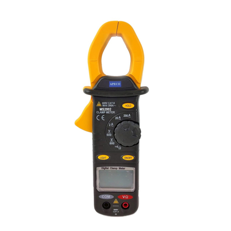
When measuring bare wires, use extra caution to
avoid electric shock.
4.5 Resistance
1. Turn off all power and discharge capacitors on the circuit under
test.
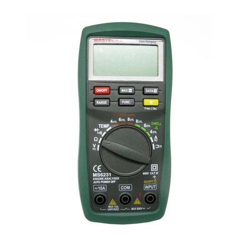
2. Insert the red test lead in the “INPUT” jack and the black lead
in the “COM” jack.
3. Move the rotary switch to the position. Connect the
test leads across the circuit to be measured.
4. Read measured resistance on the display.
Tips for measuring resistance:
- Sometimes the resistor value and measured resistance differ.
This is due to the meter’s output test current goes through all
possible paths between leads.
- For low resistance measurements, short the test leads and
record the resistance displayed. Then connect to the circuit and
subtract the recorded resistance from the measurement for the
most accurate results.
- When leads are disconnected or measurement is out of range,
only “1” is displayed.
WARNING
To avoid injury or damage to the meter, make sure to turn off
all power and discharge all capacitors before measuring
resistance.
4.6 Continuity
1. Turn off all power and discharge capacitors on the circuit under
test.
2. Insert the red test lead in the “INPUT” jack and the black lead
in the “COM” jack.
3. Move the rotary switch to the position.
Connect the test leads across the circuit to be measured.
4. Read measured resistance on the display. If the measured
resistance is less than 50Ω, the meter’s buzzer will sound.
WARNING
To avoid injury or damage to the meter, make sure to turn off
all power and discharge all capacitors before measuring
continuity.
4.7 Diode Test
1. Turn off all power and discharge capacitors on the circuit under
test.
2. Insert the red test lead in the “INPUT” jack and the black lead
in the “COM” jack.
-5-
3. Move the rotary switch to the position. Connect the test
leads across the circuit to be measured.
measured resistance is less than 50Ω, the meter’s buzzer will
sound.
WARNING
To avoid injury or damage to the meter, make sure to turn off
all power and discharge all capacitors before measuring
continuity.
4.7 Diode Test
1. Turn off all power and discharge capacitors on the circuit under
test.
2. Insert the red test lead in the “INPUT” jack and the black lead
in the “COM” jack.
3. Move the rotary switch to the position. Connect the test
leads across the circuit to be measured.
Display: 3 ½ digit LCD (max. display: 1999)
Over-range indication: display only shows “1”
Low battery indication: when battery voltage drops below
operating voltage, “ ” symbol appears on the display
Polarity indication: automatically displays “-“
Power: 3x 1.5V AAA batteries
Dimensions: 198mm*79mm*38mm
Weight: approx. 260g (with battery)
5.2 Technical Specifications
Accuracy: ±(% of reading + digits), 1 year warranty.
Ambient temp.: 18°C~28°C, humidity: <75%.
Temperature coefficient: 0.1% accuracy/°C
±(1.0% of reading + 3 digits)
- Input impedance: 10M
- Overload protection: 600V DC or AC rms
- Max. input voltage: 600V DC
±(1.5% of reading + 10 digits)
-6-
- Input impedance: 10M
- Overload protection: 600V DC or AC rms
- Max. input voltage: 600V AC rms
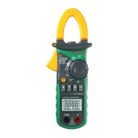
For AC current measurement, keep
the conductor in the center of the
clamp; otherwise the reading can
deviate as much as 1.5% of actual
measurement.

