Master Water Conditioning MP-MBA-15T User manual

Installation and Operation Manual
MP-MBA-15T-30T
using the
255/762 Logix Control Valve
July 2006
MASTER
Water Conditioning Corp.
www.masterwater.com

Table of Contents
Page
No.
Topic Description
1
Model #
Model Number Information
Component Packaging Description
Packaging Description
MP Logix Control Valve System
System Description
2
MP Softening System
System Positioning
Logix 255/762 Control Valve
Attaching Valve to Tank
Figure 1 & Figure 2
3
Logix 255/762 Control Valve, Cont’d
Attaching Valve to Tank
Figure 1 & Figure 2, Cont’d
Service & Drain Piping,
General Installation Layout
Drain Piping
Information
4
Service & Drain Piping,
General Installation Layout
Cont’d
Drain Piping
Figure 3, Cont’d
5
System Schematic
Piping Layout
6
Electrical Supply
Electrical Requirements
Brine Tank / Brine Tubing
Brine tank
7
Logix 255/762 Control Valve Electrical
Connection
Instructions on Logix 762
Electrical Connection
8
Filling Softener with Water
9
Filling Softener with Water
Continued
Details for Filling Softener Tank with Water
Continued
Logix 762 Control Valve Timer Settings
Setting the Timer
10
Logix 762 Control Valve Timer Settings
Continued
Setting the Timer
Continued
Final Check
Final Installation Check
11
Disinfection
Disinfecting the Unit
12
Troubleshooting
Symptom / Cause / Solution
13
Troubleshooting
Symptom / Cause / Solution
14
Troubleshooting
Symptom / Cause / Solution
15
ERR Troubleshooting
Error Troubleshooting
16
255/762 Valve Body Schematic
Parts View
17
Valve Body Parts List
Part Numbers List
18
Logix Valve Parts List
Part Numbers List
19
Warranty
Warranty

1
Installation and Operating Instructions for
255/762 Logix
Top Mount Water Softener
Model #:
_______ MP-MBA-15T 15,000 Grain Water Softener
_______ MP-MBA-30T 30,000 Grain Water Softener
Shipping Carton Description / unit:
# of
cartons
Contents Description
1
Mineral tank
Distributor pipe installed
1
Brine tank
Brine pick-up tube assembly *NOTE:
255/762 Logix valve is shipped in brine
tank.
1
255/762
Logix control
valve
255/762 timer and backwash flow
control and 256 bypass with 3/4” copper
or pvc connection
C-800
PRE-LOADED AT FACTORY
System Description:
The softener tank has a Logix top mounted automatic control valve
with an impulse meter to initiate regeneration. The Logix Valve is
constructed of non-corrosive Norylmaterial and is rated at a
maximum working water pressure of 100 psi. This softener includes
a manually operated bypass device which enables the softener to be
isolated from the water service lines for maintenance and service
while maintaining the continuity of the (untreated) water supply. It
uses a 762 microprocessor based timer in conjunction with an
internal impulse meter to actuate regeneration in the following ways:
a.Microprocessor based water meter to initiate regeneration
b.Manual regeneration button to start an emergency
regeneration
c. Calendar day override
NOTE: THIS SOFTENER IS NOT INTENDED TO BE USED FOR TREATING WATER THAT
IS MICROBIOLOGICALLY UNSAFE OR OF UNKNOWN QUALITY WITHOUT
ADEQUATE DISINFECTION WHETHER BEFORE OR AFTER THE SYSTEM.

2
NOTE: The model MP-MBA-30T has been tested and certified by the
Water Quality Association according to NSF/ANSI 44 for the specific
performance claims as verified and substantiated by test data as follows:
Rated Efficiency: 3890 Grains per pound of salt
3.5 lbs salt: 13.6 Kg Capacity
9 lbs salt: 26.7 Kg Capacity
15 lbs salt: 31.0 Kg Capacity
Rated Service Flow: 10.0 GPM @ 12 psi pressure drop
Resin: 1.0 Cubic Ft. Cation Exchange resin
Water Softener Positioning:
1. Place water softener in desired position, far enough from walls
and other obstructions to allow for servicing the unit.
2. Place the water softener within reasonable access to a grounded
115V/60 HZ circuit and a legal drain line connection.
Logix Control Valve:
1. When facing the front of the Logix timer, the inlet connection
(Figure 1) is located on the left and the outlet connection is on the
right. The control valve's inlet and outlet connections are either
3/4” copper or pvc equipped with gasket and nut.
Figure 1
Install the 256 bypass valve (See Figure 2) with inlet and outlet
handles facing upward. Place gasket into nut and secure 3/4” copper
or pvc tail piece with a nut. Repeat the procedure for the outlet
connection.
DO NOT OVERTIGHTEN THE NUT.

3
Figure 2
2. The control valve's drain connection is 1/2" npt and is located on
the back of the control valve.
3. Turn the control valve upside down and ensure that the control
valve o'rings are in place. Use silicone lubricant on the o'rings.
4. Place the control valve onto the distributor pipe.
5. Thread the control valve hand tight to 20 foot pounds!
DO NOT OVERTIGHTEN!
**DO NOT USE PETROLEUM!**
**USE ONLY SILICONE **
Service and Drain Piping:
1. Pipe water softener into the service lines .The inlet and outlet
connections of the control valve are 3/4” copper or pvc and are
located on the back of the valve body. As you face the timer the
inlet is on the left and the outlet is on the right. Always follow
local plumbing codes when installing our water treatment
equipment.
2. If sweat fittings are used, be sure soldering is done in such a
manner as not to allow heat to reach the control valve or bypass.
(If Schedule 80 PVC is used make sure to follow the proper
primer and solvent instructions.)
3. The drain line connection is located on the back of the valve as
you face the timer. It is recommended you install a 1/2” union on
the drain line for servicing. The drain line must be of adequate
size to allow for full regeneration flow.

4
Figure 3
•The control valve drain connection is 1/2" npt.
•Never decrease the drain piping size to below1/2”OD
•Maximum drain line length is 30 feet.
•Maximum drain line height is 6 feet above the
control valve.
•The drain line must be piped to an open air gap
(See Figure 3)
•Always follow local plumbing codes.
UNDER NO CIRCUMSTANCES SHOULD THERE BE A DIRECT
CONNECTION WITH SANITARY SEWAGE FACILITIES.
NOTE: The drain flow rate during regeneration (backwash)
will be:
MP-MBA-15T 1.6 GPM
MP-MBA-30T 2.5 GPM

5
Well Tank
Untreated
water from well
NOTE: All Master Water Conditioners must be
installed after the well tank or water meter if its
public water supply.
Master Water
Conditioner
Brine tank
Air Gap Drain
Overflow
fitting to
floor drain
gravity
Treated water
Untreated to outside
224 Shoemaker Rd.
Pottstown, PA 19464
Typical Piping Layout
Temperature : MAX: 120 F, MIN: 34F
Pressure: MAX: 100 PSI, MIN: 20 PSI
Electrical: 115V/ 60 HZ

6
Electrical Requirements:
Always follow all local electrical codes when installing our water
treatment equipment.
1. Provide an 115v/60Hz properly grounded dedicated electrical
outlet. (It’s very important that the polarity be correct)
Avoid using outlets that are switch controlled.
2. Maximum amperage required is 5 amps.
3. Make sure the electrical service provides power 24 hours per day.
We recommend installing a surge protector to protect unit from
power surges, which are not covered by warranty.
Brine Tank:
1. The brine tank should be located directly beside the water
softener mineral tank.
2. Connect the 3/8" poly tubing to the 3/8” white elbow compression
fitting located on the right side of the Logix control valve.
See Figure Below.
If the brine tank is equipped with a shutoff valve, the float height was
preset at the factory.

7
Logix Control Valve Electrical Connection:
Note: Do not touch the wiring harness between the Logix
timer and the motor, it’s positioning is critical and therefore
already installed at the factory.
1. Remove plastic control valve cover by spreading sides while
lifting.
2. Plug transformer into back of timer following existing wires.
3. Plug transformer into a properly grounded 120V/60 HZ electrical
outlet.
4. The screen will now change between the “Gallons Remaining to
Regeneration” and the current “Gallons per Minute” (gpm) flow
rate.

8
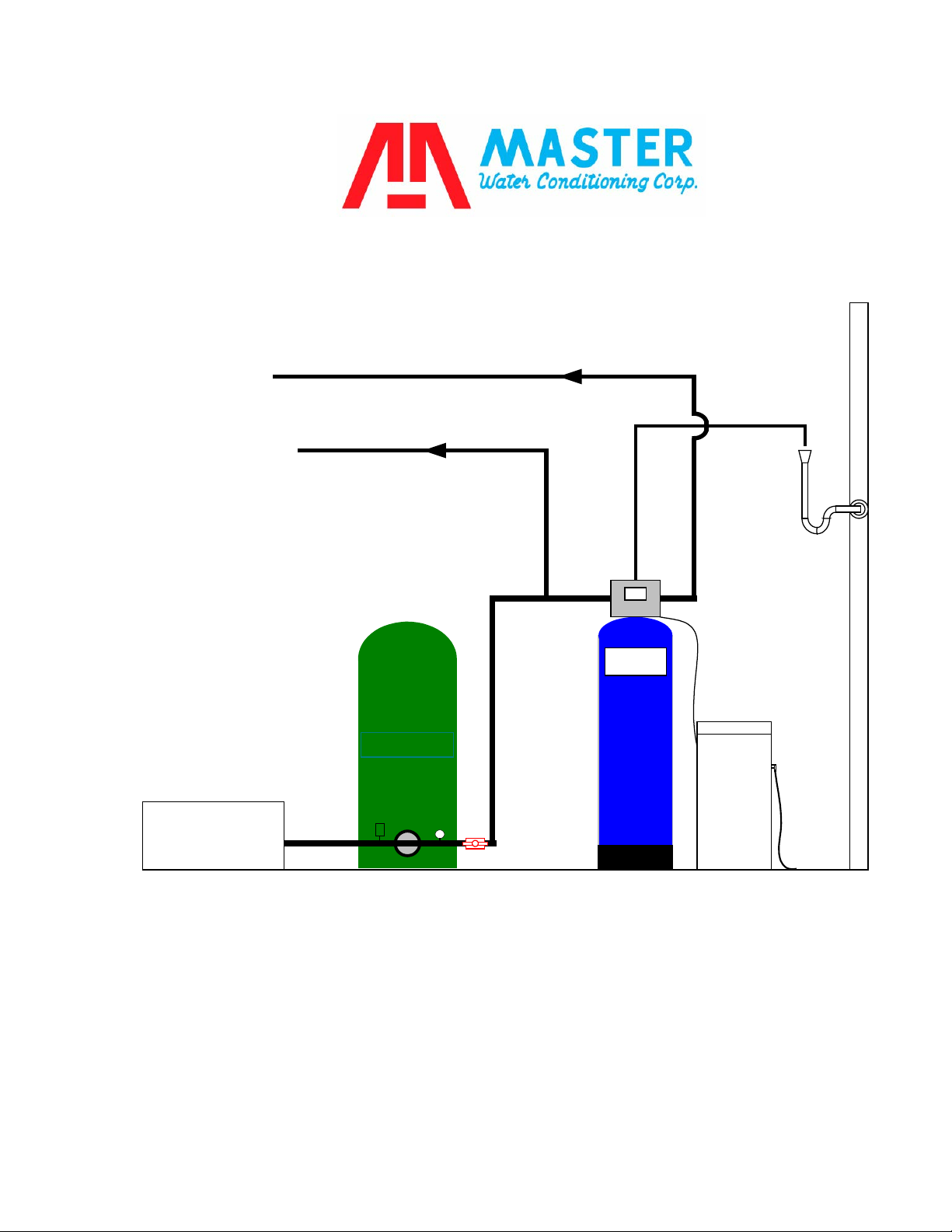
Filling Water Softener with Water:
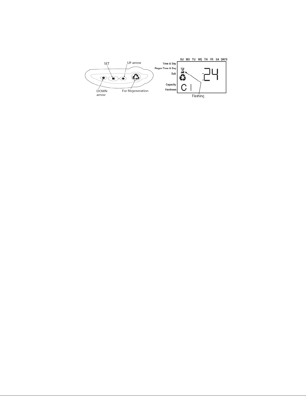
Figure 4
1. Push the FOR REGENERATION button (Figure 4) on the
controller down for 5 seconds. This will initiate a manual
regeneration. You will notice a flashing hour glass during
regeneration.
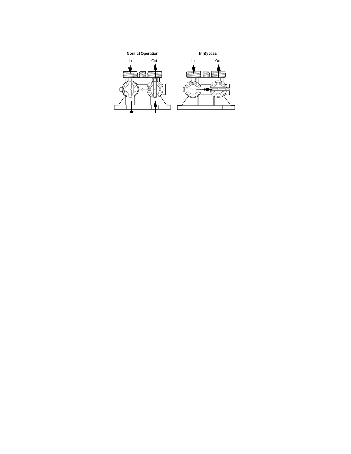
The controller will indicate that the motor is turning the camshaft
to cycle C1 (BACKWASH). The controller will indicate the total
regeneration time remaining. Filling tank in this position allows air
to escape from drain.
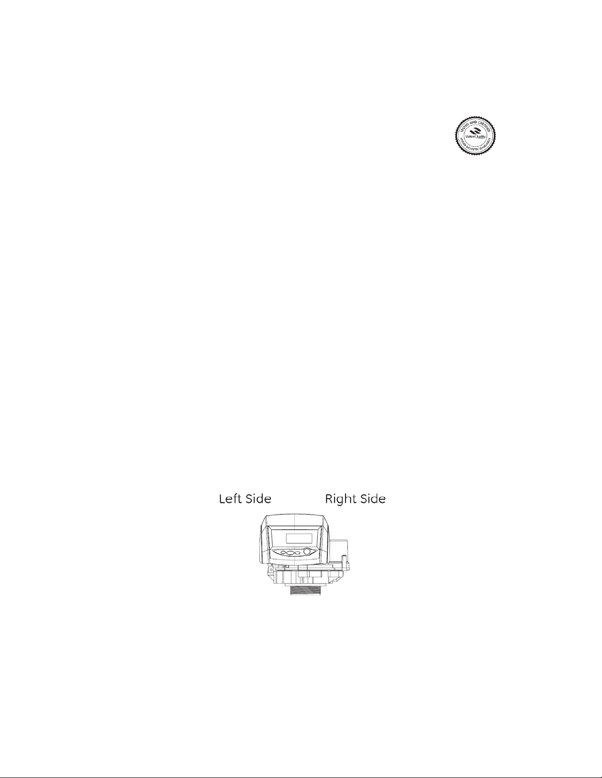
Open the bypass inlet valve ¼ turn and allow water to flow into the
mineral tank at a slow rate.
Warning: IF WATER ENTERS THE TANK TOO FAST, ALL THE
RESIN WILL BE FLUSHED TO DRAIN DURING START UP.
2. When water is running steadily at the drain, open the bypass
valve’s inlet and outlet to their maximum position.
3. Simultaneously press the SET and UP buttons on the controller
for 1 second then release, the motor will advance the cam to C2.
Once C2 is displayed simultaneously press the SET and UP
buttons on the controller for 1 second then release, the motor will
advance the cam to C3. Repeat this procedure until the timer
enters the C7 (FAST RINSE) position. The softener will go
through the rinsing cycle and then automatically advance to
(BRINE REFILL) C8 and fill the brine tank with the proper amount
of water.
4. The control valve will advance to C0 (REGENERATION
COMPLETE) and Time of Day will be displayed. This is
treated water.

9
Logix Control Valve Timer Settings:
(See Figure 5)
Note: The control valve is set at the factory. You only need to set
the hardness, time of day and regeneration time if required, which
is preset at 2 am.
Figure 5
Time of Day Setting
1) Press the SET button. The screen will show the Time of Day in blinking
numbers.
2) To change the Time of Day, use the UP or DOWN arrows.
3) Press the SET button.
Day of Week Setting
1) Press the SET button. The screen will show the Day of Week in blinking
triangle.
2) To change the Day of Week, use the UP or DOWN arrows.
3) Press the SET button.
Time of Regeneration Setting (the factory default is 2 AM)
1) Press the SET button. The screen will show the Time of Regeneration in
blinking numbers.
2) To change the Time of Regeneration, use the UP or DOWN arrows.
3) Press the SET button.
Regeneration Day Override Setting (the factory default is 0)
1) Press the SET button. The screen will show the Regeneration Day
Override in blinking numbers.
2) To change the number, use the UP or DOWN arrows.
3) Press the SET button.

10
Salt Amount Setting
1) Press the SET button. The screen will show the Salt Amount as pounds
in blinking numbers.
2) DO NOT CHANGE THE NUMBER.
3) Press the SET button.
Softening Capacity Setting
1) Press the SET button. The screen will show the Capacity as grains in
blinking numbers.
2) DO NOT CHANGE THE NUMBER.
3) Press the SET button.
Hardness Setting (the factory default is 10)
1) Press the SET button. The screen will show the Hardness as grains per
gallon in blinking numbers.
2) To change the number, use the UP or DOWN arrows.
3) Press the SET button.
Note: The screen will now flash between flow rate and
gallons remaining until next regeneration.
If water was tested by Master Water Conditioning, follow
recommendations on water analysis, for hardness
setting.
Final Check:
1. Fill the brine tank with Solar Salt and the Res-Up Feeders with Res-Up (one
quart is provided).
2. Make sure the drain line connection meets all plumbing codes and that the
drain line size can handle the backwash flow rate of the softener.
3. Make sure the Inlet and Outlet on bypass valve are open.
4. Make sure the control valve timer is plugged into an electrical outlet with
power 24 hours per day.
5. Check all piping for leaks.

11

12
Troubleshooting
Symptom: Water conditioner fails to regenerate. No soft water.
Possible Cause
Solution
Power supply to 762 control has
been interrupted.
Determine reason for power
interruption and correct. Reset time of
day.
Water pressure lost.
Restore water pressure.
For 762 series turbine failure.
Clean or replace turbine.
Corrupted programming of 762
Logix timer.
Reprogram timer assembly.
Defective 762 Logix timer.
Replace timer assembly.
No salt in brine tank.
Add salt and regenerate.
Manual bypass valve is open.
Close manual bypass valve.
Leak at riser pipe seal.
Insure that riser pipe is properly
sealed at o’ring seal. Inspect pipe for
cracks.
Insufficient brine.
Check brine float height and clean
assembly if necessary. Check flow
rate capabilities of safety float and air
check assembly.
Plugged injector or injector screen.
Inspect and clean injector and/or
injector screen.
Symptom: No Brine Draw
Possible Cause
Solution
Plugged injector or injector screen.
Inspect and clean injector and/or
injector screen.
Insufficient water pressure.
Increase water pressure above 25
psig (172kPa) minimum.
Corrupted programming of 762
Logix timer.
Reprogram timer assembly.
Defective 762Logix timer.
Replace timer assembly.
Obstructed drain line.
Remove obstruction.

13
Symptom: Insufficient brine draw
Possible Cause
Solution
Partially clogged injector or injector
screen.
Inspect and clean injector and/or
injector screen assembly.
Restricted flow rate in brine line.
Check flow rate capabilities of the
safety float/aircheck assembly.
Insufficient water pressure.
Increase water pressure above 25
psig (172kPa) minimum.
Excessive back pressure on
injector due to elevated drain line.
Reduce drain line elevation to height
of valve.
Damaged valve disk.
Replace all valve disks.
Partially restricted drain line.
Remove restriction.
Symptom: Insufficient Refill to Brine Tank
Possible Cause
Solution
Brine refill control
Remove and clean
Restricted flow rate in brine line.
Check flow rate capabilities of the
safety float/aircheck assembly.
Symptom: Excessive Water in Brine Tank
Possible Cause
Solution
Plugged drain line flow control.
Clean flow control.
Plugged injector and/or injector
screen
Inspect and clean injector and/or
screen.
Symptom: Loss of Media to Drain
Possible Cause
Solution
No flow control installed in drain
line.
Install drain line flow control.

14
Symptom: Leak to Drain
Possible Cause
Solution
No flow control installed in drain
line.
Install drain line flow control.
Insufficient water pressure.
Increase water pressure above 25
psig (172kPa) minimum.
Damaged valve disk or obstruction
in valve disk.
Inspect and if damaged, replace all
valve disks or remove obstruction.
Symptom: Loss of Water Pressure
Possible Cause
Solution
Fouled resin bed due to iron
accumulation.
Clean control valve and mineral bed
with cleaner.
Slots in riser pipe or laterals are
filled with resin fines.
Inspect and clean distributor pipe slots
as needed.
Symptom: Salt in Water to Service After Regeneration
Possible Cause
Solution
Injector is too small for system size.
Install correct injector
Brine draw time excessively long
due to low water pressure.
Increase water pressure above 25
psig (172 kPa) minimum.
Restricted drain line.
Remove drain line restriction.
Insufficient rinse volume.
Increase slow rinse time, fast rinse
time, or both.
Damaged valve disk.
Replace all valve disks.
Plugged injector and/or injector
screen.
Inspect and clean injector and/or
injector screen.

15

16

17

18
This manual suits for next models
1
Table of contents
Other Master Water Conditioning Water Dispenser manuals
Popular Water Dispenser manuals by other brands

Tana water
Tana water T-6 manual

Elkay
Elkay FGDF710-10-1G Installation, care & use manual

Hellenbrand
Hellenbrand S-12-024 Supplemental programing & cover manual

Superior
Superior 2010R owner's manual

Monarch Water
Monarch Water ULTIMATE MINI AQUA HE install guide

GE
GE GXOF18G Owner's manual and installation instructions