Master FORCE 300 N User manual

CHAIN OPERATED ACTUATOR
____
CLOUD RADIO
F
ORCE
300
N
-
MAXIMUM STROKE
400
MM
E
LECTRICAL FEEDING
230VAC
50
H
Z
INSTRUCTION MANUAL
ENGLISH
Art. 1120.8

Page 2
MASTER products are specially manufactured in safe materials in
compliance with the requirements of legislation in force. When
correctly mounted, installed and used in accordance with the
present instructions, our products constitute no danger to people,
animals or property.
Products subject to EU directives comply with the essential
requirements stipulated by the latter. markings mean that our
products can be sold and installed throughout the European
Union without any further formality.
The mark on our products, packaging and user manuals provided
with the product, indicate “presumed in conformity with directives” issued
by the EU. MASTER holds the technical file with all the documentation to
show that our products have all been inspected to ensure compliance
with directives conformity.
Symbols used in the manual
DANGER This indication draw the attention about potential
dangers for safety and health of peoples and animals.
INFORMATION This information give further suggestions.
ATTENTION This indication draw the attention about potential
dangers for the product itself.
WARNING This indication draw the attention about potential
damages to goods.
ENVIRONMENTAL
INSTRUCTION Environmental indication draw the attention about
potential dangers for the environment.

Page 3
Contents
1. Safety indications .....................................................................................................4
2. Formulas and recommendations for installation ......................................................5
2.1. Calculation of opening / closure force ............................................................5
2.2. Maximum opening according to height of sash..............................................6
3. Technical information about function........................................................................6
4. Manufacture and reference standards .....................................................................6
5. Technical data..........................................................................................................7
6. Label data and markings..........................................................................................7
7. Electric power supply................................................................................................8
7.1. Selecting the cross-section of electric power supply cables ..........................8
8. Electric power supply and sensor connection .........................................................8
8.1. Electric power supply cable............................................................................8
8.2. Cable entry to the terminal block....................................................................8
9. Electrical connection.................................................................................................9
10. Open and close commands.....................................................................................9
10.1. Remote electronic control (Radio remote control)..........................................9
10.1.1. Saving the radio remote control .........................................................10
10.1.2. Erasing the radio memory ..................................................................10
10.1.3. Remotely saving a radio remote control.............................................10
10.2. Control with conventional button ..................................................................11
10.3. Ventilation function.......................................................................................11
11. Rain detection sensor............................................................................................11
12. Predominance of the commands...........................................................................12
13. Programming actuator...........................................................................................12
13.1. Limit switches at opening .............................................................................12
13.2. Limit switches at closure...............................................................................12
14. Assembly...............................................................................................................13
14.1. Preparation of actuator for assembly ...........................................................13
14.2. Assembly with outward opening window.....................................................14
14.3. Assembly on transom window......................................................................15
14.4. Assembly of actuator onto bay or outward opening window........................16
14.5. Configurations ..............................................................................................17
15. Meaning of the LED flashing mode .......................................................................18
16. Checking for correct assembly..............................................................................18
17. Emergency manoeuvres, maintenance and cleaning ...........................................19
18. Troubleshooting ....................................................................................................19
19. Environmental protection.......................................................................................20
20. Certificate of guarantee .........................................................................................20
21. Conformity .............................................................................................................21

Page 4
1.Safety indications
ATTENTION
B
EFORE INSTALLING THIS APPLIANCE
,
ENSURE ALL SAFETY INDICATIONS
HAVE BEEN READ CAREFULLY AND UNDERSTOOD IN ORDER TO PREVENT CONTACT WITH
ELECTRICITY
,
INJURY OR ANY OTHER INCIDENT
.
THE MANUAL SHOULD BE CONSERVED
FOR FURTHER CONSULTATION AT A LATER DATE
.
Series CLOUD RADIO chain actuators have been designed to move windows.
Use for any applications other than those indicated must be authorised by the
manufacturer after technical review of the assembly.
The following safety indications should be observed carefully.
The appliance must be installed by competent and qualified technical personnel.
After removing packaging, check for any damage on the appliance.
Plastic bags, polystyrene, small metal parts such as nails, staples etc should be
placed out of the reach of children as they constitute a potential source of risk.
Before connecting the appliance, check that the power supply has the same
specifications as those indicated on the technical data label on the appliance.
This machine is destined exclusively for the use for which it has been designed
and the manufacturer accepts no responsibility for damage incurred by improper
use.
The actuator is destined exclusively for installation indoors. For any special
application we recommend you consult the manufacturer beforehand.
Power supply installation must comply with any regulations in force.
To ensure efficient separation from the grid, an approved type of bipolar pulse
switch should be used. An omnipolar general power switch with minimum distance
of 3 mm between contacts should be installed upstream of the control line.
Do not use solvents or jets of water to wash the appliance. The appliance should
not be submerged in water.
Repairs should only be performed by qualified personnel at assistance centres
authorised by the manufacturer.
Always request exclusive use of original spare parts. Failure to respect this
condition could compromise safety and invalidate the benefits contained in the
warranty for the appliance.
In the event of any problems or queries, consult your agent or contact the
manufacturer directly.

Page 5
WARNING
With bottom hung windows injury could be caused if the window accidentally falls.
An appropriately sized flexible link arm or fall prevention safety system designed to
resist a force equal to at least three times the total weight of the window MUST be
installed.
Danger of crushing or dragging. During function, when the actuator closes the
window, a force of 300N is exerted on the bead of the frame, enough to crush
fingers in the event of distraction.
Ensure that the stroke-end selection is less than one centimetre from mechanical
stop blocks, stroke limiters or any physical obstacles blocking opening of the sash.
In the event of breakage or malfunction, switch the appliance off at the general
switch and call for the services of a qualified technician.
2.Formulas and recommendations for installation
2.1. Calculation of opening / closure force
Using the formulas below, approximate calculations can be made for the force required to
open or close the window considering all the factors that determine the calculation.
Symbols used for the calculation
F (Kg) = Force for opening or closing P (Kg) = Weight of the window (mobile sash only)
C (cm) = Opening stroke (actuator stroke) H (cm) = Height of the mobile sash
For horizontal light domes or
skylights
F = 0.54 x P
(Eventual weight of snow or wind on the
cupola should be calculated separately).
For vertical windows
TOP HUNG WINDOWS
,
OUTWARD OPENING
(A)
BOTTOM HUNG WINDOWS
(B)
F = 0.54 x P x C : H
(Eventual load of favourable or unfavourable
wind on the sash should be calculated
separately.)

Page 6
2.2. Maximum opening according to height of sash
The actuator stroke is in accordance with the height of the sash and its application. Check
that the actuator stroke does not touch the profile of the sash and that the chain does not
exert force on the window frame (measurements in mm).
A
TTENTION
.For safety reasons the actuator should not be assembled if dimensions
are inferior to those indicated in the table below. In the event that the height of the
sash should be lower, call on the manufacturer to check the appliance.
Mode of installation Selection of actuator stroke
100 200 300 400
Light domes, skylights or vertical top hung windows
opening outwards with frontal assembly
150 250 350 450
Top hung windows opening outwards with
horizontal assembly
150 250 350 450
Bottom hung windows (motor on frame)
250 450 600 700
Bottom hung windows (motor on sash)
Consult manufacturer
3.Technical information about function
The chain operated actuator opens and closes windows by means of a steel chain located
inside the cover. Movement is powered by electricity which powers a gear motor controlled
by an electronic function device.
Window opening can be programmed to open at 100, 200, 300 and 400 mm (see
respective chapter).
During closure the end course uses a self-regulating electronic process with power
absorption and therefore requires no regulation.
The actuator leaves the factory with factory settings of +1 cm for the return course which
allows the actuator to be assembled without electricity, with the window in closed position
after assembly is complete.
4.Manufacture and reference standards
•The CLOUD RADIO chain operated actuator has been designed and produced to open
and close bay or outward opening windows, hopper frame windows, dormer windows,
cupolas and skylights. It has been specifically designed for providing ventilation and air
circulation of areas. It can also be used in combination with the operated rain sensors
(Art. 1120.51).
•Electrical connections must conform to regulations in force for the design and set up of
electrical equipment.
•The actuator has been manufactured in accordance with European Union directives and
has been certified in conformity with marking.
•Any eventual service and control device for the actuator must be manufactured in
accordance with regulations in force and must conform to respective European
Community regulation.

Page 7
The CLOUD RADIO actuator is packed in one single carton. Each package contains:
•Actuator with 2 metre (±5%) lead.
•Standard support brackets with distancer (A).
•Bracket for vertical assembly of the actuator (B).
•Bracket for transom window (C).
•Bracket for outward opening fixture (D).
•Template for boring.
•Instruction manual.
5.Technical data
MODEL
CLOUD RADIO
Pressure and traction force 300 N
Track runs (can be selected at any time) 100, 200, 300, 400 mm
Voltage 110/230V~ (a.c.) 50/60 Hz
Current consumption at nominal charge 0,160 A
Current consumption with no charge 0,020 A
Charge absorbed at nominal load ~ 28 W
No load speed 12 mm/s
No load duration (400 mm) 30 s
Double electrical insulation YES
Type of service S
2
of 3 min
Working temperature - 5 + 65 ºC
Protection index IP30
Adjustment of socket at casing Autopositioning
Static hold force 1.700 N
Connection of two or more devices in parallel YES
Limit switch stop at opening Electronic
Limit switch stop at closure At absorption of charge
Dimensions 386,5x59x37
Weight 1,170 kg
Weight – as delivered 1,350 Kg
Any information reported in this table is not binding and may be susceptible to variations without notice
6.Label data and markings
The actuators have been assigned marking and can be sold onto the market and used
throughout European Union territory without further requirement.
The marking on the product, packaging and user warnings indicate “presumed
conformity to directives” issued by the EEC.
The manufacturer holds technical archives with documentation to prove that products have
been examined to assess conformity to directives.
Rating plate data is located on an adhesive polyethylene label on the outside of the
container, printed in blue on a grey background. All data conform to stipulations required
by community standards in force.

Page 8
7.Electric power supply
Warning. Check that the electric power supply used corresponds to that
specified on the “technical data” label attached to the machine.
The manufacturer cannot be held liable for damage due to an application
which is incorrect or non-compliant with regulatory requirements.
The actuator is powered by a mains voltage, in alternating current, of 110/230V~(AC)
(+15%, -10%) with a frequency of 50/60 Hz.
The actuator is already equipped with a power supply cable which is 2 meters long. The
cable has two colored conductors: Phase (brown) and Neutral (sky-blue).
The connection between the line and the power supply cable of the actuator must be
protected by a magnetothermic switch between the line and actuator.
7.1. Selecting the cross-section of electric power supply cables
The cross-section of the electric power supply conductors must comply with current
standards on electrical systems, without prejudice to standard EN 60335 for connected
electrical devices.
8.Electric power supply and sensor connection
8.1. Electric power supply cable
The power supply cable is already wired to the actuator. It is used for the electric power
supply of the system and should be connected to the electricity mains. The power
supply cable has two conductors: sky-blue, brown.
8.2. Cable entry to the terminal block
The cables entering on the left, in the same cable feedthrough, are the following low-
voltage cables:
•Rain sensor cable (Art. 1120.51).
•Manual open/close control cable.
After the wiring is completed (see the “Electrical
connection” chapter) and the cables and cable
feedthrough are arranged properly, it is
recommended that the cable entry be sealed with a
drop of silicone; this will prevent humidity or water
from entering.

Page 9
9.Electrical connection
E
LECTRIC SHOCK HAZARD
.
Before beginning any work on the machine's wiring, make certain that the
electric power has been disconnected; failure to observe this rule may
compromise safety.
Cable entry to the terminal block
•No connection to the symbols
indicated to the side.
FUNCTION NOT PRESENT in this
system.
•Connection of the rain detection sensor.
-Red (+) connected to +15V,
-Black (-) connected to -15V,
-Blue (N.O. contact) connected to “
PIOGGIA
”,
-Green (common) connected to -15V,
-Violet (N.C. contact) not used and should be
electrically isolated.
•Connection of the manual control with 3
conductors [the common conductor on (
COM
), the
conductor for opening on (IN 1) and the conductor
for closing on (IN 2)].
10. Open and close commands
10.1. Remote electronic control (Radio remote control)
The WI-CONTROL radio remote control is the standard-equipped device for controlling
the CLOUD RADIO motor.
For more details on the characteristics and operation of the WI-CONTROL radio remote
control, consult the instructions manual provided with the radio remote control itself.
Some functions of the radio remote control are not discussed in this manual.
T
HE TRANSMITTER IS
NOT
FACTORY
-
PROGRAMMED
.
First follow the radio remote control instructions and then those provided below
concerning the specific operation of the machine you would like to control.

Page 10
10.1.1. Saving the radio remote control
The radio remote control supplied is the WI-CONTROL model, with 30 channels and a
display, which transmits at the radio frequency of 433.92 MHz; no other radio remote
control model is provided for the
CLOUD
RADIO. Several actuators can be controlled with
a single radio remote control, however each channel must correspond to a CLOUD RADIO
actuator and thus a window.
The encoding used varies for each channel, so each transmission will send a signal that is
different from all the others. It follows that the receiver must be able to recognize the
enabled transmitters, thus the transmission codes should be saved following the procedure
below:
Equip yourself with the radio remote control, checking beforehand that it is working,
has charged batteries and is in good condition.
Select the desired channel on the radio remote control. (Consult the instructions
manual of the WI-CONTROL radio remote control).
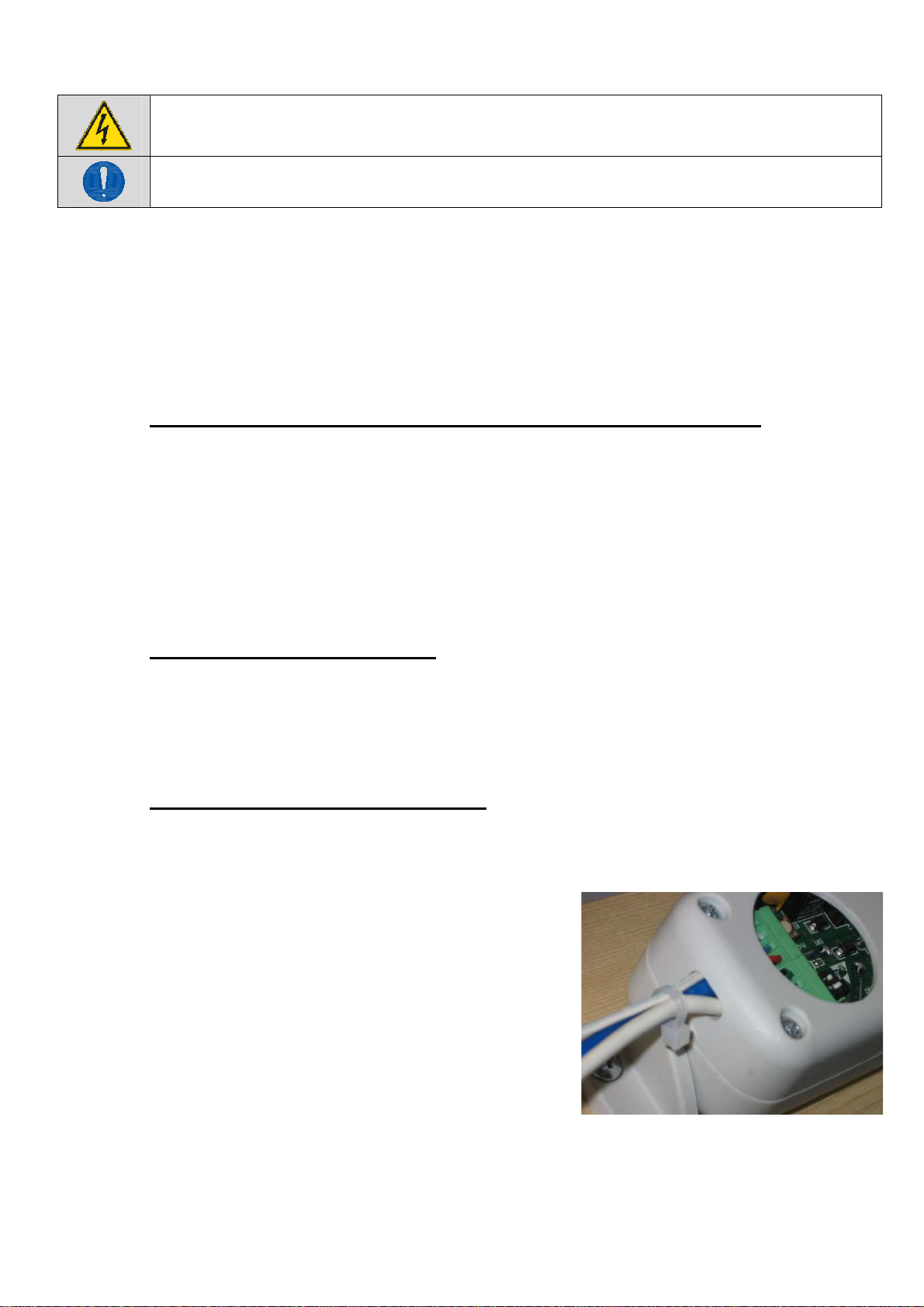
On the CLOUD RADIO, briefly press (for about 1 second) the small “
PRG
”button
located near the terminal block. The slowly flashing LED indicates that it is waiting to
receive a valid radio code.
Within 10 seconds, press any one of the up arrow ▲,
STOP
or down arrow ▼buttons
two times (once to activate the display of the radio remote control and the second
time to transmit the radio code).
If the code is saved correctly, the LED will emit one long flash (1 sec.) to confirm;
then the LED will go out and remain at rest.
If the code is not saved correctly - due to the memory being full, for example, or the
radio remote control being incompatible - the LED will emit a series of quick flashes
for about 1 second; then the LED will go out and remain at rest.
10.1.2. Erasing the radio memory
To completely erase the memory of the radio remote control on the machine, press the
“
PRG
”button and hold it pressed for about 20 seconds until the LED begins to flash quickly.
At this point you can release the button; the flashing continues until the memory has been
completely erased.
10.1.3. Remotely saving a radio remote control
A new radio remote control can be saved remotely – i.e., without accessing the
PRG
button
– only if at least one radio remote control has already been saved as described in point
10.1.1 and you have the radio remote control which is already recognized. To remotely
save a radio remote control, follow the procedure below:
Equip yourself with the WI-CONTROL radio remote control to be saved and set it on
the desired channel (see the instructions provided with the radio remote control).
Equip yourself with the radio remote control already saved and operating on the
CLOUD RADIO in question.
On the already saved radio remote control, press the following buttons in sequence:
F1, F2 and then
STOP
. This sequence “opens” the memory of the CLOUD RADIO (in
the same way as pressing the PRG button).

Page 11
Within 10 seconds, press any one of the up arrow ▲,
STOP
or down arrow ▼buttons of
the (new) radio remote control that you want to program two times (once to activate the
display of the radio remote control and the second time to transmit the radio code).
10.2. Control with conventional button
If necessary, due to unavailability of the radio remote control or other reason, the controls
can be connected by cable.
The control must have a clean (voltage-fee) single-pole contact, normally open, or a
deadman's button, but not a stable switch. It should be connected to the left terminal block
in the actuator, as indicated in the previous “Electrical connection” chapter.
Warning. The IN1 and IN2 controls prevail over the radio commands.
The manual control prevails over radio remote control.
10.3. Ventilation function
The commands issued by the radio remote control can include a specific function called
“V
ENTILATION
”, which has the purpose of ventilating the room naturally for a specified time.
To activate this function, press the following buttons in sequence: F1, F2, up arrow ▲.
The window opens and, if no other commands are given, closes again automatically after 5
minutes. In the case in which the rain sensor, a manual command or radio command
intervened, the ventilation function stops; to restore the function, the sequence of buttons
must be pressed again.
11. Rain detection sensor
The rain sensor should be installed outside on the window frame and fixed with a screw or
weather-resistant adhesive system. The device acts only on the commands of the chain
actuator.
Warning. The command coming from the rain sensor prevails over any other
command; if a stable switch is assembled with the manual control and forced
opening is instructed, after having reached the opening stroke-end the window
closes again, then it opens again, then closes again, etc.
In order to prevent this problem from arising, do not assemble a stable control
switch.
The Rain Sensor (Art. 1120.51) is a universal sensor with relay output and voltage-free
change-over contact (it can also be used by other systems), with a heater that operates
below +4 °C.
12. Predominance of the commands
The rain sensor intervenes when it rains regardless of the state of the commands, i.e., the
closing command due to rain, if activated, prevails over any manual command.

Page 12
13. Programming actuator
13.1. Limit switches at opening
Four (4) positions can be selected for the limit switch of the outgoing chain. To program,
adjust the two dip-switches near left terminal board, as indicated in the following table.
1
2
100
OFF
OFF
200
ON
OFF
300
OFF
ON
400
ON
ON
Limit switch at:
(mm)
Dip-switch n°
After the limit switches have been programmed, run a few check manoeuvres. In the event
of error, programming can be repeated to give the desired track run.
The actuator comes from production set on longer stroke (400 mm), dip-switch 1
in ON; dip-switch 2 in ON.
13.2. Limit switches at closure
The limit switch at closure is automatic, electronically operated and cannot be
programmed.
The actuator stops when the charge is absorbed when the window is completely closed
and the weather stripping is completely depressed, or when the charge absorbed is more
than 15% of the nominal charge.
Attention. The actuator at maximum charge, exercises a traction force of over
350N; this force is enough to crush fingers in the event of distraction.
After each closure or intervention of the electrical protection mechanism, the
chain moves in the opposite direction for around 1,0/1,5 mm. This is to loosen
the tension of the mechanical parts and gives correct pressure to the weather
stripping.

Page 13
14. Assembly
These indications are intended for the attention of technicians and specialized
personnel. Basic job and safety techniques are therefore not included.
All preparatory operations, assembly and electrical connections must be carried out by
technical and specialized personnel to guarantee best performances and good function of
the CLOUD RADIO chain operated actuator.
First of all, please check that the following fundamental points have been satisfied:
Actuator specifications must be sufficient for movement of the window without
encountering any obstacle. The limits indicated in the technical data table must
not be superseded (page 7) and the most appropriate stroke should be selected.
Calculations should be checked using the formula indicated on page 6.
Ensure that the actuator has not been damaged during transport, first visually
and then by powering in both directions.
Check that the width of the inside of the window (where the actuator is to be
assembled) is over 405 mm, otherwise the actuator should not be installed.
Check that once the actuator has been installed the
distance between the fixed part of the window frame
(where the actuator is to be assembled) and the
mobile part of the window frame (where the bracket is
to be fixed) is greater than or equal to 0 mm (Fig. 1). If
this is not the case the actuator will not function
correctly as the window will not close correctly. If
required, add additional thickness below the support
brackets to reset the quota.
14.1. Preparation of actuator for assembly
Before starting assembly of the actuator, prepare the following material for completion,
equipment and tools.
For fixing onto metal window frames: M5 threaded inserts (6 pieces), M5x12 flat
headed metric screws (6 pieces).
For fixing onto wooden window frames: self-threading screws for wood Ø4.5 (6
pieces).
For fixing onto PVC window frames: self-threading screws for metal Ø4.8 (6 pieces).
Equipment and tools: measuring tape, pencil, drill/screwdriver, set of drill heads for
metal, insert for screwing in, electricians pliers, screwdrivers.
Figure 1

Page 14
14.2. Assembly with outward opening window.
Aside the drawing of specific application using
accessories provided. For different mountings, please
contact manufacturer.
A.
Pencil in an “X” over the centre line of the window frame
(Fig. 2).
B.
Select the correct form of brackets (Fig. 3).
C.
Attach the template to the window frame (fixed part) and
line axis up with the centre line “X” traced earlier (Fig. 4).
Warning: for window frames not on the same plane, cut
the part of the template coloured in grey and fix this to
the moveable part of the window frame, taking care to
keep it in the same position.
D.
Bore holes in the window frame at the points indicated
on the template (Fig. 5).
E.
Assemble the two brackets with the distancer (to help
position correctly. Once it has served its purpose it can
be removed). Mount the supports onto the frame with the
appropriate screws provided. Check that everything is
aligned both horizontally and vertically.
F.
Mount the bracket for outward opening windows onto the
moveable part of the frame in accordance with the
markings indicated on the template.
G.
Complete assembly of the chain terminal with the safety
clip inserted onto the pin Ø4x32 (provided) in median
position (see fig. 6).
H.
Mount the actuator onto the brackets by inserting the two
openings at each side onto the corresponding pins on
the brackets.
I.
Rotate the actuator 90°, bring the chain terminal up to
the bracket and insert the pin into the opening on the
bracket. Insert the safety clip into the bracket.
J.
Check that the exit on the chain is perfectly aligned with
the bracket. If the chain is not aligned with the bracket,
loosen the fixing screws and reposition the bracket
correctly.
K.
Check all electrical connections with the diagram on the
label attached to the lead and and in conformity to
indications on chapter 9 – Electrical connection.
L.
Carry out a complete check of opening and closure of
the window. Once the closure phase has been
completed, check that the window frame is completely
closed by checking the pressure on the weather strips.
Outward application
Figure 2
Figure 3
Figure 4
Figure 5
Figure 6

Page 15
14.3. Assembly on transom window
Aside the drawing of specific application using
accessories provided. For different mountings, please
contact manufacturer.
Before starting, check that there are at least two
mechanical compass safety stops or other form of
stops connected to the frame, and ensure that the
stops can prevent any accidental fall of the window.
Your safety is at hand.
A.
Pencil in an “X” over the centre line of the window frame
(Fig. 7).
B.
Select the correct form of brackets (Fig. 8).
C.
Attach the template to the window frame (fixed part) and
line axis up with the centre line “X” traced earlier (Fig. 9).
Warning: for window frames not on the same plane, cut
the part of the template coloured in grey and fix this to
the moveable part of the window frame, taking care to
keep it in the same position.
D.
Bore holes in the window frame at the points indicated
on the template (Fig. 10).
E.
Assemble the two brackets with the distancer (to help
position correctly. Once it has served its purpose it can
be removed). Mount the supports onto the frame with the
appropriate screws provided. Check that everything is
aligned both horizontally and vertically.
F.
Mount the bracket for outward opening windows onto the
moveable part of the frame in accordance with the
markings indicated on the template.
G.
Complete assembly of the chain terminal with the safety
clip inserted onto the provided pin Ø4x32 in median
position (see fig. 11).
H.
Mount the actuator onto the brackets by inserting the two
openings at each side onto the corresponding pins on
the brackets.
I.
Rotate the actuator 90°, bring the chain terminal up to
the bracket and insert the pin into the opening on the
bracket. Insert the safety clip into the bracket.
J.
Check that the exit on the chain is perfectly aligned with
the bracket. If the chain is not aligned with the bracket,
loosen the fixing screws and reposition the bracket
correctly.
K.
Check all electrical connections with the diagram on the
label attached to the lead and in conformity to indications
on chapter 9 – Electrical connection.
L.
Carry out a complete check of opening and closure of
the window. Once the closure phase has been
completed, check that the window frame is completely
closed by checking the pressure on the weather strips.
Inward application – transom
window
Figure 7
Figure 8
Figure 9
Figure 10
Figure 11

Page 16
14.4. Assembly of actuator onto bay or outward opening window.
Aside the drawing of specific application using
accessories provided. For different mountings, please
contact manufacturer.
A.
Pencil in an “X” over the centre line of the window frame
(fig. 12).
B.
Select the correct form of brackets (fig. 13).
C.
Fold the template along the green dotted line and keep
in position at 90°. Attach one part to the window frame
(fixed part), taking care to line up the axis with the “X”
previously pencilled in on the central line and line the
folded part up against the moveable part of the frame.
Warning: as various different applications are possible,
place the actuator in a central position and adjust the
positions of the brackets, taking care to keep the
actuator aligned with the window section.
D.
Bore holes into the window frame at the points indicated
(fig. 14).
E.
Mount the bracket for outward opening windows onto the
moveable part of the frame in accordance with the
markings indicated on the template.
F.
Complete assembly of the chain terminal with the safety
clip inserted onto the provided pin Ø4x32 in median
position (see fig. 15).
G.
Mount the two brackets on to the sides of the actuator.
H.
Position the actuator onto the window frame and line up
with the holes bored earlier. Fix the actuator.
I.
Bring the chain terminal up to the bracket and insert the
pin into the hole on the bracket. Attach the safety clip to
the bracket.
J.
Check that the exit of the chain is perfectly aligned with
the bracket. If the chain is not aligned, loosen the fixing
screws and reposition the bracket correctly.
K.
Check all electrical connections with the diagram on the
label attached to the lead and in conformity to
indications on chapter 9 – Electrical connection.
L.
Carry out a complete check of opening and closure of the
window. Once the closure phase has been completed,
check that the window frame is completely closed by
checking the pressure on the weather strips.
Vertical assembly on outward
opening
Figure 12
Figure 13
Figure 14
Figure 15

Page 17
14.5. Configurations

Page 18
15. Meaning of the LED flashing mode
The LED can be seen on the electronic board after removing the closure plug. In some
cases it flashes in different ways depending on the signal it is emitting; the different
flashing modes indicate the precise behavior of the actuator during the programming of the
machine, radio remote control or rain sensor.
The table below summarizes the meaning of the LED flashing mode.
Ref.
Flashing Flashing frequency Meaning
1 Off Actuator at rest, no alarm is active
2 Steady-on Function not provided for
3 Slow flashing for
10 seconds 1 per second The machine is waiting to receive a valid
radio remote control code.
4 On for
2 seconds Steady-on The machine has saved the radio
remote control correctly
5 Flashing for
2 seconds 2 per second The machine has not saved the radio
remote control
6 Fast continuous
flashing 2 per second Rain sensor active
7 Flashing for 5
seconds 2 per second Erasing the radio remote control memory
16. Checking for correct assembly
Check that the window has closed completely, even at the corners, and check
there are no obstacles caused by assembly in the wrong position.
Check that when the window frame is closed, the chain terminal is at least a
couple of millimetres distant from the actuator body. This will ensure correct
closure of the window with correct pressure on the weather stripping. If the chain
terminal is not positioned as stated there is no guarantee the window will close
correctly.
Check that all attachments and support brackets are tightly fixed to the window
frame and that all screws are correctly tightened.
Check that the window moves to the desired position in accordance with the limit
switch selected.

Page 19
17. Emergency manoeuvres, maintenance and cleaning
Should the window have to be opened manually in the event of no electricity, mechanical
failure, or for normal maintenance or cleaning of the external surface of the window frame,
the following instructions should be followed:
1. Release the safety clip locking the chain terminal to
the bracket.
2. Hold the window with one hand and pull the pin out of
the opening with the other hand (Fig. 16).
3. Manually open the window frame.
A
TTENTION
:
DANGER
– the window could fall as
the sash is no longer held in position by the
chain.
4. After maintenance and/or cleaning repeat points 1 and
2 in reverse order.
18. Troubleshooting
Please consult the following table for any eventual problems with function during
installation or normal use:
Problem Possible cause Solution
Actuator doesn’t
work •No electricity supply for feeder.
•Connecting cable not connected
or wire not connected.
•Winder on the transformer is
broken.
•Check state of safety switch.
•Check all electrical
connections of gear motor.
•Replace the electronics card
of the feeder.
LED is lit but
actuator doesn’t
work.
•Gear motor is damaged due to a
shock. Motor connection has
unsoldered or has been
disconnected.
•Send actuator to a Service
Centre.
Although selection
has been carried
out correctly the
gearmotor will not
take a limit switch.
•Programming hasn’t been
carried out correctly.
•Irregular function or break in the
electrical contact for the dip-
switch.
•Repeat programming for dip-
switch.
•Send actuator to a Service
Centre.
Actuator does not
move. •The radio command has not
been accepted by the radio
receiver.
•Repeat the memorisation
procedure for the radio
command.
Rain sensor does
not close window.
•
The sensor is not a 1120.51
model.
•Sensor if faulty.
•Replace the sensor with a
proper model.
•Send sensor to a Service
Centre.
Figure 16

Page 20
19. Environmental protection
All materials used in the manufacture of this appliance are recyclable.
We recommend that the device itself, and any accessories, packaging, etc. be sent to a centre for
ecological recycling as established from laws in force on recycling.
The device is mainly made from the following materials: aluminium, zinc, iron, plastic of various type,
cuprum. Dispose materials in conformity with local regulations about removal.
20. Certificate of guarantee
The manufacturer will guarantee good function of the appliance. The manufacturer shall undertake to
replace defective parts due to poor quality materials or manufacturing defects in accordance with article
1490 of the Civil Code.
The guarantee covers products and individual parts for 2 years from the date of purchase. The latter is valid
as long as the purchaser possesses proof of purchase and completion of all agreed conditions of payment.
Guarantee of good function of appliances agreed by the manufacturer implies that the latter undertakes to
repair or replace free of charge and in the shortest period possible any parts that break while under
warranty.
The purchaser is not entitled to any reimbursement for eventual direct or indirect damage or other expenses
incurred. Attempt to repair by personnel unauthorised by the manufacture shall render the warranty null and
invalid.
The warranty does not cover fragile parts or parts subject to natural wear and tear or corrosion, overload,
however temporary etc. The manufacturer will accept no responsibility for eventual damage incurred by
erroneous assembly, manoeuvre or insertion, excessive stress or inexpert use.
Repairs performed under guarantee are always "ex factory of the manufacturer". Respective transport
expenses (out/back) are the responsibility of the purchaser.
This manual suits for next models
1
Table of contents
Popular Radio manuals by other brands

DEGEN
DEGEN DE13 Operation manual

FONESTAR
FONESTAR TOUR-1T quick start guide

iRonsnow
iRonsnow IS-388 user manual

First Alert
First Alert Public Alert WX-167 quick start guide

Directed Electronics
Directed Electronics Honda/Acura SIRIUS Interface HON-SC1 installation guide

Coopers of Stortford
Coopers of Stortford G040 Instructions for use