Masterack 022553KP Programming manual

MASTERACK Headquarters
2400 Mellon Court
Decatur, GA 30035
800-222-8785
Before starng installaon,
review this document to ensure that
all parts and hardware are included
in the package.
!
MASTERACK.COM

2
MASTERACK.COM
Full Size Ulity Carrier
Assembly / Installaon Instrucons
2400 Mellon Court, Decatur, GA 30035
Phone: 1-800-222-8785
www.masterack.com
Page 1of 14
RM470505 Rev 2.2
ASSEMBLY / INSTALLATION INSTRUCTIONS
Recommended Tools
Hardware
FULL SIZE UTILITY CARRIER
022553KP
3/8
FLAT WASHER
3/8
E-STOP NUT
3/8-16 x 3/4
CARRIAGE BOLT
!
Before starng installaon,
review this document to ensure that
all parts and hardware are included
in the package.
■
■
■
2400 Mellon Court, Decatur, GA 30035
Phone: 1-800-222-8785
www.masterack.com
Page 1of 14
RM470505 Rev 2.2
ASSEMBLY / INSTALLATION INSTRUCTIONS
Recommended Tools
Hardware
FULL SIZE UTILITY CARRIER
022553KP
3/8
FLAT WASHER
3/8
E-STOP NUT
3/8-16 x 3/4
CARRIAGE BOLT
2400 Mellon Court, Decatur, GA 30035
Phone: 1-800-222-8785
www.masterack.com
Page 1of 14
RM470505 Rev 2.2
ASSEMBLY / INSTALLATION INSTRUCTIONS
Recommended Tools
Hardware
FULL SIZE UTILITY CARRIER
022553KP
3/8
FLAT WASHER
3/8
E-STOP NUT
3/8-16 x 3/4
CARRIAGE BOLT
2400 Mellon Court, Decatur, GA 30035
Phone: 1-800-222-8785
www.masterack.com
Page 1of 14
RM470505 Rev 2.2
ASSEMBLY / INSTALLATION INSTRUCTIONS
Recommended Tools
Hardware
FULL SIZE UTILITY CARRIER
022553KP
3/8
FLAT WASHER
3/8
E-STOP NUT
3/8-16 x 3/4
CARRIAGE BOLT

MASTERACK.COM
Full Size Ulity Carrier
Assembly / Installaon Instrucons
■
2400 Mellon Court, Decatur, GA 30035
Phone: 1-800-222-8785
www.masterack.com
Page 2of 14
RM470505 Rev 2.2
EXPLODED VIEW
1
1
2
2
2
3
3
3
3
2
4
4
4
4

4
MASTERACK.COM
Full Size Ulity Carrier
Assembly / Installaon Instrucons
■
2400 Mellon Court, Decatur, GA 30035
Phone: 1-800-222-8785
www.masterack.com
Page 3of 14
RM470505 Rev 2.2
COMPONENTS
1
CROSS BOW
P/N
–025714
4
INNER CLAMP (FOOT)
P/N –022744
3
OUTTER CLAMP
P/N –022743
2
CROSS BOW
P/N –025714
2400 Mellon Court, Decatur, GA 30035
Phone: 1-800-222-8785
www.masterack.com
Page 3of 14
RM470505 Rev 2.2
COMPONENTS
1
CROSS BOW
P/N –025714
4
INNER CLAMP (FOOT)
P/N –022744
3
OUTTER CLAMP
P/N –022743
2
CROSS BOW
P/N
–025714
2400 Mellon Court, Decatur, GA 30035
Phone: 1-800-222-8785
www.masterack.com
Page 3of 14
RM470505 Rev 2.2
COMPONENTS
1
CROSS BOW
P/N –025714
4
INNER CLAMP (FOOT)
P/N –022744
3
OUTTER CLAMP
P/N
–022743
2
CROSS BOW
P/N –025714
2400 Mellon Court, Decatur, GA 30035
Phone: 1-800-222-8785
www.masterack.com
Page 3of 14
RM470505 Rev 2.2
COMPONENTS
1
CROSS BOW
P/N –025714
4
INNER CLAMP (FOOT)
P/N
–022744
3
OUTTER CLAMP
P/N –022743
2
CROSS BOW
P/N –025714

5
MASTERACK.COM
Full Size Ulity Carrier
Assembly / Installaon Instrucons
2400 Mellon Court, Decatur, GA 30035
Phone: 1-800-222-8785
www.masterack.com
Page 4of 14
RM470505 Rev 2.2
ATTACHING INNER CLAMP TO FRONT CROSSBOW
VEHICLE
FRONT FEET O. D.
Chevrolet
58-1/2”
Ford
64”
FRONT CROSSBOW FOOT PLACEMENT
GUIDE
OUTSIDE DIMENSION OF FEET (O.D.)
TORQUE SETTING:
Size - 3/8 = 22-30 Ft.-Lbs.
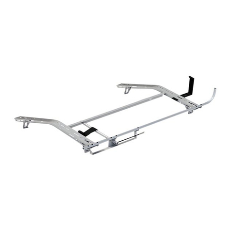
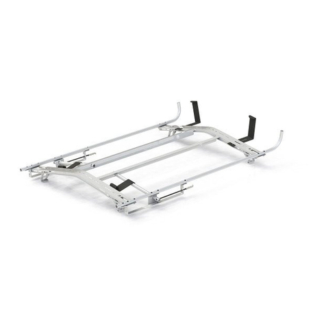
ATTACHING INNER CLAMPS (FEET)
Attach Inner clamps to each end as shown, using:
(4) 3/8-16 x 3/4 Carriage Bolts,
(4) 3/8 Washers and (4) 3/8 E-Stop Nuts per clamp.
NOTE: THE DISTANCE BETWEEN THE FEET IS MAKE SPECIFIC.
USE THE CHART BELOW FOR FULL SIZE VAN DIMENSIONS.
FRONT CROSSBOW
2400 Mellon Court, Decatur, GA 30035
Phone: 1-800-222-8785
www.masterack.com
Page 4of 14
RM470505 Rev 2.2
ATTACHING INNER CLAMP TO FRONT CROSSBOW
VEHICLE
FRONT FEET O. D.
Chevrolet
58-1/2”
Ford
64”
FRONT CROSSBOW FOOT PLACEMENT
GUIDE
OUTSIDE DIMENSION OF FEET (O.D.)
TORQUE SETTING:
Size - 3/8 = 22-30 Ft.-Lbs.
ATTACHING INNER CLAMPS (FEET)
Attach Inner clamps to each end as shown, using:
(4) 3/8-16 x 3/4 Carriage Bolts,
(4) 3/8 Washers and (4) 3/8 E-Stop Nuts per clamp.
NOTE: THE DISTANCE BETWEEN THE FEET IS MAKE SPECIFIC.
USE THE CHART BELOW FOR FULL SIZE VAN DIMENSIONS.
FRONT CROSSBOW
■
ATTACHING INNER CLAMPS (FEET)
Aach Inner clamps to each end as shown, using:
(4) 3/8-16 x 3/4 Carriage Bolts,
(4) 3/8 Washers and (4) 3/8 E-Stop Nuts per clamp.
NOTE: THE DISTANCE BETWEEN THE FEET IS
MAKE SPECIFIC. USE THE CHART BELOW FOR
FULL SIZE VAN DIMENSIONS.
2400 Mellon Court, Decatur, GA 30035
Phone: 1-800-222-8785
www.masterack.com
Page 4of 14
RM470505 Rev 2.2
ATTACHING INNER CLAMP TO FRONT CROSSBOW
VEHICLE
FRONT FEET O. D.
Chevrolet
58-1/2”
Ford
64”
FRONT CROSSBOW FOOT PLACEMENT
GUIDE
OUTSIDE DIMENSION OF FEET (O.D.)
TORQUE SETTING:
Size - 3/8 = 22-30 Ft.-Lbs.
ATTACHING INNER CLAMPS (FEET)
Attach Inner clamps to each end as shown, using:
(4) 3/8-16 x 3/4 Carriage Bolts,
(4) 3/8 Washers and (4) 3/8 E-Stop Nuts per clamp.
NOTE: THE DISTANCE BETWEEN THE FEET IS MAKE SPECIFIC.
USE THE CHART BELOW FOR FULL SIZE VAN DIMENSIONS.
FRONT CROSSBOW
2400 Mellon Court, Decatur, GA 30035
Phone: 1-800-222-8785
www.masterack.com
Page 4of 14
RM470505 Rev 2.2
ATTACHING INNER CLAMP TO FRONT CROSSBOW
VEHICLE
FRONT FEET O. D.
Chevrolet
58-1/2”
Ford
64”
FRONT CROSSBOW FOOT PLACEMENT
GUIDE
OUTSIDE DIMENSION OF FEET (O.D.)
TORQUE SETTING:
Size - 3/8 = 22-30 Ft.-Lbs.
ATTACHING INNER CLAMPS (FEET)
Attach Inner clamps to each end as shown, using:
(4) 3/8-16 x 3/4 Carriage Bolts,
(4) 3/8 Washers and (4) 3/8 E-Stop Nuts per clamp.
NOTE: THE DISTANCE BETWEEN THE FEET IS MAKE SPECIFIC.
USE THE CHART BELOW FOR FULL SIZE VAN DIMENSIONS.
FRONT CROSSBOW
2400 Mellon Court, Decatur, GA 30035
Phone: 1-800-222-8785
www.masterack.com
Page 4of 14
RM470505 Rev 2.2
ATTACHING INNER CLAMP TO FRONT CROSSBOW
VEHICLE
FRONT FEET O. D.
Chevrolet
58-1/2”
Ford
64”
FRONT CROSSBOW FOOT PLACEMENT
GUIDE
OUTSIDE DIMENSION OF FEET (O.D.)
TORQUE SETTING:
Size - 3/8 = 22-30 Ft.-Lbs.
ATTACHING INNER CLAMPS (FEET)
Attach Inner clamps to each end as shown, using:
(4) 3/8-16 x 3/4 Carriage Bolts,
(4) 3/8 Washers and (4) 3/8 E-Stop Nuts per clamp.
NOTE: THE DISTANCE BETWEEN THE FEET IS MAKE SPECIFIC.
USE THE CHART BELOW FOR FULL SIZE VAN DIMENSIONS.
FRONT CROSSBOW

6
MASTERACK.COM
Full Size Ulity Carrier
Assembly / Installaon Instrucons
2400 Mellon Court, Decatur, GA 30035
Phone: 1-800-222-8785
www.masterack.com
Page 4of 14
RM470505 Rev 2.2
ATTACHING INNER CLAMP TO FRONT CROSSBOW
VEHICLE
FRONT FEET O. D.
Chevrolet
58-1/2”
Ford
64”
FRONT CROSSBOW FOOT PLACEMENT
GUIDE
OUTSIDE DIMENSION OF FEET (O.D.)
TORQUE SETTING:
Size - 3/8 = 22-30 Ft.-Lbs.
ATTACHING INNER CLAMPS (FEET)
Attach Inner clamps to each end as shown, using:
(4) 3/8-16 x 3/4 Carriage Bolts,
(4) 3/8 Washers and (4) 3/8 E-Stop Nuts per clamp.
NOTE: THE DISTANCE BETWEEN THE FEET IS MAKE SPECIFIC.
USE THE CHART BELOW FOR FULL SIZE VAN DIMENSIONS.
FRONT CROSSBOW
2400 Mellon Court, Decatur, GA 30035
Phone: 1-800-222-8785
www.masterack.com
Page 4of 14
RM470505 Rev 2.2
ATTACHING INNER CLAMP TO FRONT CROSSBOW
VEHICLE
FRONT FEET O. D.
Chevrolet
58-1/2”
Ford
64”
FRONT CROSSBOW FOOT PLACEMENT
GUIDE
OUTSIDE DIMENSION OF FEET (O.D.)
TORQUE SETTING:
Size - 3/8 = 22-30 Ft.-Lbs.
ATTACHING INNER CLAMPS (FEET)
Attach Inner clamps to each end as shown, using:
(4) 3/8-16 x 3/4 Carriage Bolts,
(4) 3/8 Washers and (4) 3/8 E-Stop Nuts per clamp.
NOTE: THE DISTANCE BETWEEN THE FEET IS MAKE SPECIFIC.
USE THE CHART BELOW FOR FULL SIZE VAN DIMENSIONS.
FRONT CROSSBOW
■
ATTACHING INNER CLAMPS (FEET)
Aach Inner clamps to each end as shown, using:
(4) 3/8-16 x 3/4 Carriage Bolts,
(4) 3/8 Washers and (4) 3/8 E-Stop Nuts per clamp.
NOTE: THE DISTANCE BETWEEN THE FEET IS
MAKE SPECIFIC. USE THE CHART BELOW FOR
FULL SIZE VAN DIMENSIONS.
2400 Mellon Court, Decatur, GA 30035
Phone: 1-800-222-8785
www.masterack.com
Page 5of 14
RM470505 Rev 2.2
ATTACHING INNER CLAMP TO REAR CROSSBOW
VEHICLE
REAR FEET O. D.
Chevrolet
57-1/2”
Ford
63”
REAR CROSSBOW FOOT PLACEMENT
GUIDE
OUTSIDE DIMENSION OF FEET (O.D.)
TORQUE SETTING:
Size - 3/8 = 22-30 Ft.-Lbs.
ATTACHING INNER CLAMPS (FEET)
Attach Inner clamps to each end as shown, using:
(4) 3/8-16 x 3/4 Carriage Bolts,
(4) 3/8 Washers and (2) 3/8 E-Stop Nuts per clamp.
NOTE: THE DISTANCE BETWEEN THE FEET IS MAKE SPECIFIC.
USE THE CHART BELOW FOR FULL SIZE VAN DIMENSIONS.
REAR CROSSBOW
2400 Mellon Court, Decatur, GA 30035
Phone: 1-800-222-8785
www.masterack.com
Page 4of 14
RM470505 Rev 2.2
ATTACHING INNER CLAMP TO FRONT CROSSBOW
VEHICLE
FRONT FEET O. D.
Chevrolet
58-1/2”
Ford
64”
FRONT CROSSBOW FOOT PLACEMENT
GUIDE
OUTSIDE DIMENSION OF FEET (O.D.)
TORQUE SETTING:
Size - 3/8 = 22-30 Ft.-Lbs.
ATTACHING INNER CLAMPS (FEET)
Attach Inner clamps to each end as shown, using:
(4) 3/8-16 x 3/4 Carriage Bolts,
(4) 3/8 Washers and (4) 3/8 E-Stop Nuts per clamp.
NOTE: THE DISTANCE BETWEEN THE FEET IS MAKE SPECIFIC.
USE THE CHART BELOW FOR FULL SIZE VAN DIMENSIONS.
FRONT CROSSBOW
2400 Mellon Court, Decatur, GA 30035
Phone: 1-800-222-8785
www.masterack.com
Page 5of 14
RM470505 Rev 2.2
ATTACHING INNER CLAMP TO REAR CROSSBOW
VEHICLE
REAR FEET O. D.
Chevrolet
57-1/2”
Ford
63”
REAR CROSSBOW FOOT PLACEMENT
GUIDE
OUTSIDE DIMENSION OF FEET (O.D.)
TORQUE SETTING:
Size - 3/8 = 22-30 Ft.-Lbs.
ATTACHING INNER CLAMPS (FEET)
Attach Inner clamps to each end as shown, using:
(4) 3/8-16 x 3/4 Carriage Bolts,
(4) 3/8 Washers and (2) 3/8 E-Stop Nuts per clamp.
NOTE: THE DISTANCE BETWEEN THE FEET IS MAKE SPECIFIC.
USE THE CHART BELOW FOR FULL SIZE VAN DIMENSIONS.
REAR CROSSBOW

7
MASTERACK.COM
Full Size Ulity Carrier
Assembly / Installaon Instrucons
■
Aach (2) Side Stops to each end of the
Cross Bows as shown, using:
(2) 3/8-16 x 1 Carriage Bolts
(2) 3/8 Washers
(2) 3/8 E-Stop Nuts
(PER STOP)
2400 Mellon Court, Decatur, GA 30035
Phone: 1-800-222-8785
www.masterack.com
Page 6of 14
RM470505 Rev 2.2
ATTACHING SIDE STOPS
Attach (2) Side Stops to each end of the
Cross Bows as shown, using:
(2) 3/8-16 x 1 Carriage Bolts
(2) 3/8 Washers
(2) 3/8 E-Stop Nuts
((PER STOP)
TORQUE SETTING:
Size - 3/8 = 22-30 Ft.-Lbs.

8
MASTERACK.COM
Full Size Ulity Carrier
Assembly / Installaon Instrucons
2400 Mellon Court, Decatur, GA 30035
Phone: 1-800-222-8785
www.masterack.com
Page 7of 14
RM470505 Rev 2.2
Loosely attach (4) OUTER CLAMPS at locations shown here using
(4) 3/8 Flat Washers and (4) 3/8 E-Stop Nuts.
TORQUE SETTING:
Size - 3/8 = 22-30 Ft.-Lbs.
ATTACHING OUTER CLAMPS
■
Loosely aach (4) OUTER CLAMPS at
locaons shown here using
(4) 3/8 Flat Washers and (4) 3/8 E-Stop Nuts.
2400 Mellon Court, Decatur, GA 30035
Phone: 1-800-222-8785
www.masterack.com
Page 7of 14
RM470505 Rev 2.2
Loosely attach (4) OUTER CLAMPS at locations shown here using
(4) 3/8 Flat Washers and (4) 3/8 E-Stop Nuts.
TORQUE SETTING:
Size - 3/8 = 22-30 Ft.-Lbs.
ATTACHING OUTER CLAMPS
2400 Mellon Court, Decatur, GA 30035
Phone: 1-800-222-8785
www.masterack.com
Page 7of 14
RM470505 Rev 2.2
Loosely attach (4) OUTER CLAMPS at locations shown here using
(4) 3/8 Flat Washers and (4) 3/8 E-Stop Nuts.
TORQUE SETTING:
Size - 3/8 = 22-30 Ft.-Lbs.
ATTACHING OUTER CLAMPS

9
MASTERACK.COM
Full Size Ulity Carrier
Assembly / Installaon Instrucons
■
2400 Mellon Court, Decatur, GA 30035
Phone: 1-800-222-8785
www.masterack.com
Page 8of 14
RM470505 Rev 2.2
PLACEMENT GUIDE

10
MASTERACK.COM
Full Size Ulity Carrier
Assembly / Installaon Instrucons
2400 Mellon Court, Decatur, GA 30035
Phone: 1-800-222-8785
www.masterack.com
Page 9of 14
RM470505 Rev 2.2
APPLICABLE TO CARAVAN INSTALLATION
Loosely attach the (4) MOUNTING FEET to the CROSSBOWS using
(2) 3/8"-16 x 1" HWH SCREWS,
(2) 3/8" WASHERS and
(2) 3/8" E-Stop Nuts
PER MOUNTING FOOT.
DO NOT TIGHTEN YET. PLACE THE LADDER RACK ASSEMBLY ON TOP OF THE
VEHICLE. ADJUST THE MOUNTING FEET IN OR OUT WHILE
CENTERING THE LADDER RACK.
OUTSIDE DIMENSION OF FEET (O.D.)
44-3/4"
■
Loosely aach the (4) MOUNTING FEET
to the CROSSBOWS using
(2) 3/8”-16 x 1” HWH SCREWS,
(2) 3/8” WASHERS and
(2) 3/8” E-Stop Nuts
PER MOUNTING FOOT. DO NOT TIGHTEN YET.
PLACE THE LADDER RACK ASSEMBLY ON
TOP OF THE VEHICLE. ADJUST THE MOUNTING
FEET IN OR OUT WHILE CENTERING THE
LADDER RACK.
2400 Mellon Court, Decatur, GA 30035
Phone: 1-800-222-8785
www.masterack.com
Page 9of 14
RM470505 Rev 2.2
APPLICABLE TO CARAVAN INSTALLATION
Loosely attach the (4) MOUNTING FEET to the CROSSBOWS using
(2) 3/8"-16 x 1" HWH SCREWS,
(2) 3/8" WASHERS and
(2) 3/8" E-Stop Nuts
PER MOUNTING FOOT.
DO NOT TIGHTEN YET. PLACE THE LADDER RACK ASSEMBLY ON TOP OF THE
VEHICLE. ADJUST THE MOUNTING FEET IN OR OUT WHILE
CENTERING THE LADDER RACK.
OUTSIDE DIMENSION OF FEET (O.D.)
44-3/4"

11
MASTERACK.COM
Full Size Ulity Carrier
Assembly / Installaon Instrucons
■
Remove the Ulity Carrier to allow working space
and drill eight 7/16” diameter holes through the
roof where marked. Your drilled holes should
straddle the roof crossmember at the rear. At the
front, one hole will fall to the front of the roof
crossmember and the other hole will go through
the roof crossmember.
2400 Mellon Court, Decatur, GA 30035
Phone: 1-800-222-8785
www.masterack.com
Page 10 of 14
RM470505 Rev 2.2
Remove the Utility Carrier to allow working space and drill
eight 7/16" diameter holes through the roof where marked.
Your drilled holes should straddle the roof crossmember at the rear.
At the front, one hole will fall to the front of the roof crossmember
and the other hole will go through the roof crossmember.
REAR
CROSSMEMBER
FRONT
CROSSMEMBER
MOUNTING
PLATES
Remove the Utility Carrier to allow working space and drill
eight 7/16" diameter holes through the roof where marked.
Your drilled holes should straddle the roof crossmember at the rear.
At the front, one hole will fall to the front of the roof crossmember
and the other hole will go through the roof crossmember.
7/16
HOLE
APPLICABLE TO CARAVAN INSTALLATION
Remove the Ulity Carrier to allow working space and drill eight 7/16” diameter holes through the
roof where marked. Your drilled holes should straddle the roof crossmember at the rear. At the
front, one hole will fall to the front of the roof crossmember and the other hole will go through
the roof crossmember.

12
MASTERACK.COM
Full Size Ulity Carrier
Assembly / Installaon Instrucons
■
Reposion the Ulity Carriers and place the (8) SPONGES between each of the MOUNTING FEET
and the roof. Insert (8) 3/8” NEOPRENE WASHERS and (8) 3/8” x 1-1/2” SCREWS through each
of the holes in the MOUNTING FEET from the top.
2400 Mellon Court, Decatur, GA 30035
Phone: 1-800-222-8785
www.masterack.com
Page 11 of 14
RM470505 Rev 2.2
Reposition the Utility Carriers and place the (8) SPONGES between each of the MOUNTING FEET and the roof. Insert (8) 3/8" NEOPRENE WASHERS and
(8) 3/8" x 1-1/2" SCREWS through each of the holes in the MOUNTING FEET from the top.
NUT
WASHER
SPONGE
Place the (2) STIFFENER PLATES over the rear crossmember so that the holes
in the STIFFENER PLATE line up with the holes in the
MOUNTING PLATES. Do not attach to the MOUNTING PLATE yet.
Note: The slots in the STIFFENER PLATES should be offset to the center of the
vehicle. Mark through the rearmost
slot in each STIFFENER PLATE onto the crossmember. Remove the
STIFFENER PLATE to allow for drilling.
Center punch the marks and drill a 3/8" diameter hole into the crossmember on
each side. Install (2) PLUSNUTS into 3/8" pilot holes
using (1) 1/4"-20 x 1" HWH SCREW. Remove SCREW after installation of
PLUSNUT.
(See next page for PlusNut info)
AT
REAR
CROSSMEMBER
ONLY
SCREW
STIFFENER
PLATE
PLUSNUT
APPLICABLE TO CARAVAN INSTALLATION
Place the (2) STIFFENER PLATES over the
rear crossmember so that the holes in the
STIFFENER PLATE line up with the holes in
the MOUNTING PLATES. Do not aach to
the MOUNTING PLATE yet. Note: The slots
in the STIFFENER PLATES should be oset
to the center of the vehicle. Mark through
the rearmost slot in each STIFFENER PLATE
onto the crossmember. Remove the
STIFFENER PLATE to allow for drilling.
Center punch the marks and drill a 3/8”
diameter hole into the crossmember on each
side. Install (2) PLUSNUTS into 3/8” pilot
holes using (1) 1/4”-20 x 1” HWH SCREW.
Remove SCREW aer installaon of
PLUSNUT. (See next page for PlusNut info)

MASTERACK.COM
Full Size Ulity Carrier
Assembly / Installaon Instrucons
■
!
2400 Mellon Court, Decatur, GA 30035
Phone: 1-800-222-8785
www.masterack.com
Page 12 of 13
RM470447
BEFORE DRILLING
CHECK ALL MOUNTING LOCATIONS TO PREVENT PENETRATING
GAS LINES, GAS TANKS, BRAKE LINES, WIRING OR ANY OTHER STRUCTURE OF VEHICLE
CHECK EACH BOLT LOCATION
to ensure they are tightened to the specified
torque setting.
TORQUE SETTING:
Size –1/4 GRD 5 = 7-9.6 Ft.-Lbs.
Size –1/4 GRD 8 = 10- 13.5 Ft.-Lbs.
The Plusnut® is pre-bulbed for easy installation
1
The Plusnut® is pre-assembled with hex cap and hex bolt.
Then it is inserted into a pre-drilled hole
2
As the bolt is tightened, the Plusnut® upsets
and provides outstanding
blind fastening holding power
3
C-500 tool tightens bolt thru hex head cap into Plusnut® A
ratchet, open-end or closed –end wrench can be used.
4
Fully upset Plusnut® provides
a reliable nut plate for fastening.
5
USE DRILL STOP TO PREVENT
DAMAGING VEHICLE
DRILL CHUCK
DRILL STOP
DRILL BIT
USE DRILL STOP TO
PREVENT DAMAGING VEHICLE
2400 Mellon Court, Decatur, GA 30035
Phone: 1-800-222-8785
www.masterack.com
Page 12 of 13
RM470447
BEFORE DRILLING
CHECK ALL MOUNTING LOCATIONS TO PREVENT PENETRATING
GAS LINES, GAS TANKS, BRAKE LINES, WIRING OR ANY OTHER STRUCTURE OF VEHICLE
CHECK EACH BOLT LOCATION
to ensure they are tightened to the specified
torque setting.
TORQUE SETTING:
Size –1/4 GRD 5 = 7-9.6 Ft.-Lbs.
Size –1/4 GRD 8 = 10- 13.5 Ft.-Lbs.
The Plusnut® is pre-bulbed for easy installation
1
The Plusnut® is pre-assembled with hex cap and hex bolt.
Then it is inserted into a pre-drilled hole
2
As the bolt is tightened, the Plusnut® upsets
and provides outstanding
blind fastening holding power
3
C-500 tool tightens bolt thru hex head cap into Plusnut® A
ratchet, open-end or closed –end wrench can be used.
4
Fully upset Plusnut® provides
a reliable nut plate for fastening.
5
USE DRILL STOP TO PREVENT
DAMAGING VEHICLE
DRILL CHUCK
DRILL STOP
DRILL BIT

14
MASTERACK.COM
Full Size Ulity Carrier
Assembly / Installaon Instrucons
■
Replace the STIFFENER PLATES over the
MOUNTING PLATES and secure with
(2) 1/4” SPLIT LOCK WASHER and
(2) 1/4”-20 X 1” HWH SCREW
2400 Mellon Court, Decatur, GA 30035
Phone: 1-800-222-8785
www.masterack.com
Page 13 of 14
RM470505 Rev 2.2
Replace the STIFFENER PLATES over the MOUNTING PLATES and secure with
(2) 1/4" SPLIT LOCK WASHER and
(2) 1/4"-20 X 1" HWH SCREW
SCREW
LOCK
WASHER
Place (8) 3/8" WASHERS and (8) 3/8" E-Stop Nuts on all
3/8" x 1-1/2" SCREWS
and tighten to a recommended torque of 30ft-lbs.
FAILURE TO PERFORM THIS STEP
COULD RESULT IN VEHICLE DAMAGE.
NUT
WASHER
APPLICABLE TO CARAVAN INSTALLATION
Place (8) 3/8” WASHERS and (8) 3/8”
E-Stop Nuts on all 3/8” x 1-1/2”
SCREWS and ghten to a recommended
torque of 30-lbs.
FAILURE TO PERFORM THIS STEP
COULD RESULT IN VEHICLE DAMAGE.

15
MASTERACK.COM
Full Size Ulity Carrier
Assembly / Installaon Instrucons
®
MASTERACK® commercial van and pickup equipment is warranted to be from defects in material and
workmanship, under normal use and service for a period of one (1) year from date of purchase. Factory
installaons, and products installed in new vehicles by an authorized MASTERACK® installer are warranted
for (3) years or 36,000 miles (60,000KM), whichever comes rst.
• Addions, alteraons, or installaons made by persons including dealers,other than MASTERACK® and
it’s authorized distributors, made in accordance with MASTERACK® specicaons and / or instrucons,
nor to defects arising out of aribute to such addions, alteraons or installaons.
• Defects aributable to abuse or misuse of the product, misapplicaon, negligent accident,
modicaon or tampering.
• Damage resulng from failure to promptly nofy and comply with the instrucons of the dealer or
manufacturer about defects when noted.
• Any incidental or consequenal damages connected with a defect, either while under warranty or
aerward, including the cost of a rental truck and / or loss or revenue.
®
Warranty claims must be submied to either your sales representave or a customer service
representave at 816-455-0218. The vehicle must be delivered to the original MASTERACK® authorized
dealer for inspecon and any warranty service. Any warranty service to be performed by a source other
than MASTERACK® locaon or an approved MASTERACK® distributor must be authorized in advance of
the repairs by the MASTERACK® Warranty Administrator and a purchase order issued by MASTERACK®
in advance or repairs for the authorized repairs.
FULL_SIZE_UTILITY_CARRIER_INSTALL_REV1212020
Table of contents
Other Masterack Automobile Accessories manuals
Popular Automobile Accessories manuals by other brands

Classic Accessories
Classic Accessories QUAD GEAR instructions

Pioneer
Pioneer CA-HM-SUZ.002 installation manual

ARB
ARB AIRLOCKER RD208 installation guide

Rugged Ridge
Rugged Ridge 13551.32 manual

Safe Fleet
Safe Fleet PRIME DESIGN FBM-1015-BLK Assembly instructions

AVS
AVS Ventvisor installation instructions