Socket Installation
Safety Warning
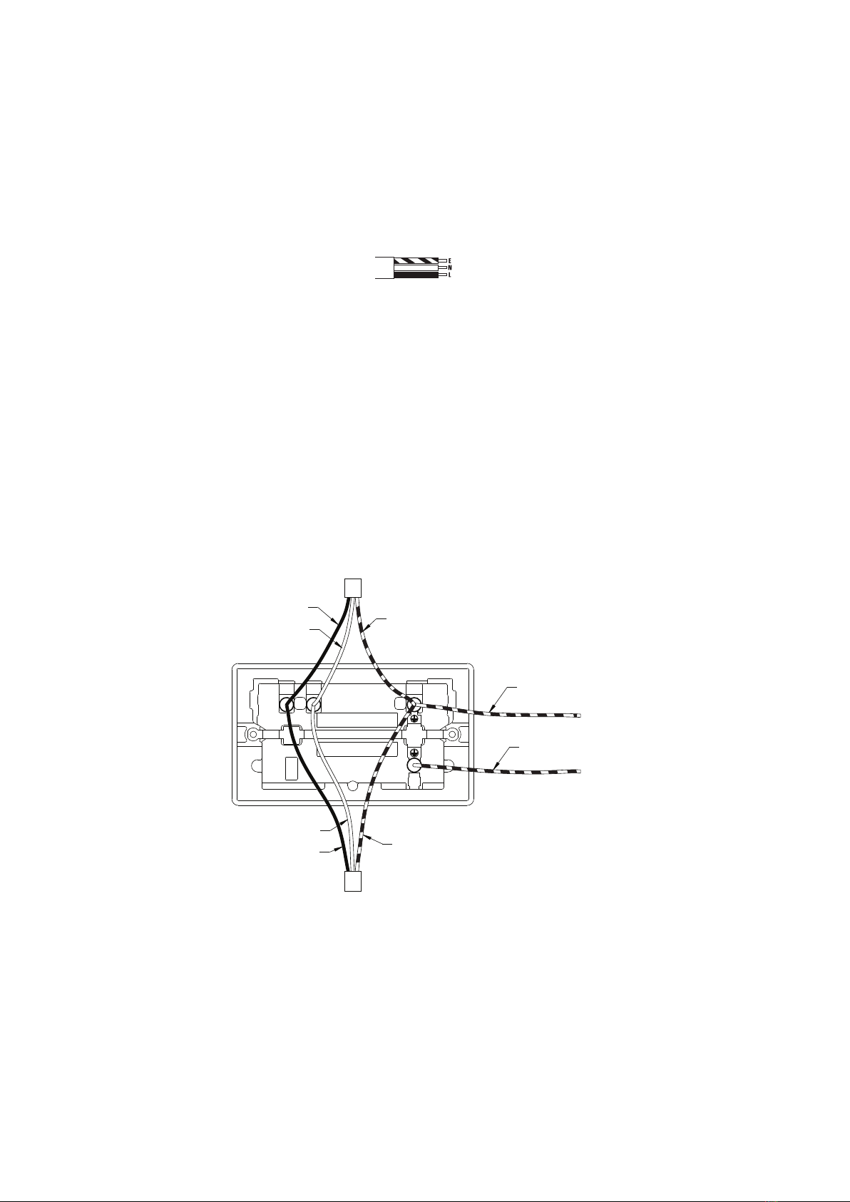
Wiring Instructions
3. Connection
FUNCTIONAL EARTH
NEUTRAL
EARTH
LIVE
NEUTRAL
EARTH
LIVE
TO MOUNTING BOX
EARTH TERMINAL
LE
N
For your safety, this product must be installed in accordance with local Building Regulations. If in any doubt, or where required by the
law, consult a competent person who is registered with an electrical self-certification scheme. Further information is available online or
from your Local Authority.
Please read carefully and use in accordance with these safety wiring instructions. Before commencing any electrical work ensure the
supply is switched off at the mains. Either by switching off the consumer unit or by removing the appropriate fuse or turning off MCB
(trip). Wiring should be in accordance with the latest edition of the IET regulations (BS 7671).
To prevent fire hazard always use cable of the correct rating & type for the application.
Warning do not exceed the load rating of this device as stated on the rear of the product.
Wire Identification – Twin & Earth Cable
Note - As from 1st April 2004 new colour codes for hard wire installations were introduced.
EARTH = Green/Yellow Sleeving
NEUTRAL = Black (pre Apr 04) / Blue (after Apr 04)
LIVE = Red (pre Apr 04) / Brown (after Apr 04)
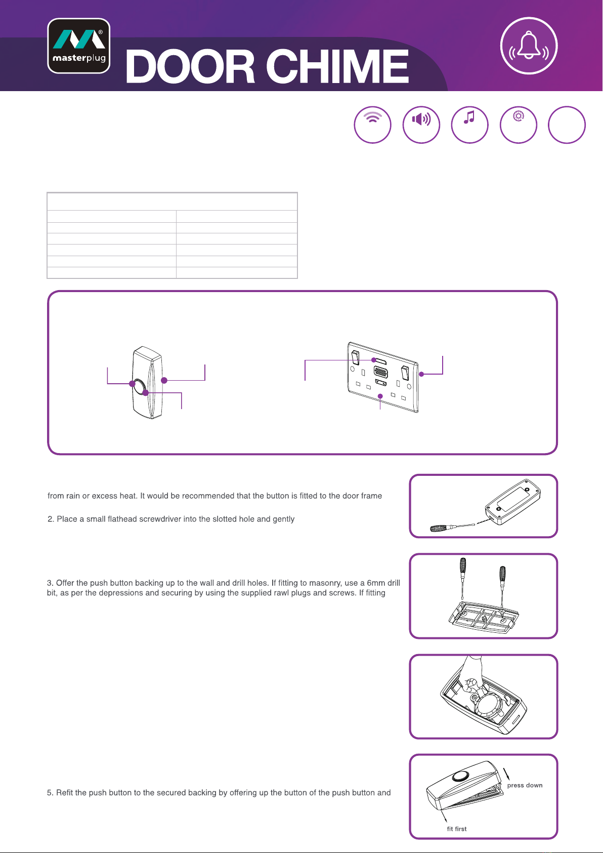
2a. Replacing an existing accessory
1. Unscrew the accessory from the wall/mounting box.
2. Note the cable connections: The illustration shows 1 wire of each colour connected to each terminal. There should be an additional
connection between the mounting box earth terminal and the accessory earth terminal.
3. Unscrew each terminal to release the wire.
2b. New installation
1. Install mounting box (metal or moulded) for either flush or surface mounting, ensuring appropriate size of product.
2. Select the most suitable entry point of the mounting box (knock-out) and route the cables through. If a metal box is used, a cable
grommet should be fitted to the entry point.
3. Cables should be prepared so a sufficient conductor length reaches the terminals. Strip the ends of the individual conductors leaving an
adequate length bare to enter terminals.
1. Line up the new accessory to mounting box and take note of where each terminal is located.
2. Connect each wire to the matching terminal. An earth connection should always be made between the mounting box earth terminal and
the accessory earth terminal, where fitted. All bare earth wires must be sheathed with green/yellow sleeving. When connecting the new
accessory ensure that only the bare end of the wire enters the terminal and no bare wires are visible.
3. Tighten terminal screws securely. (Do not over tighten)
4. This socket is fitted with two linked terminals to provide a dual earth facility. This is for use in “clean” installations where additional earth
capacity is required to comply with Regulation 607 IEE Wiring Regulations.
4. Complete Installation & Test
1. Carefully position the accessory into the mounting box, ensuring that no wires are trapped between the plate and the wall and secure
with screws (do not over tighten) then insert screw covers (optional).
2. Once the installation has been completed correctly, replace the fuse/reset MCB (trip), switch the power back on at the consumer unit and
test.
Unique Code Selection
The door chime and push button will be paired straight out of the box, with 1 out of 1 million unique codes to prevent interference with
another door chime. If the door chime does not sound, please refer to the 'Pairing Additional Push Buttons & Door Chimes' section.
1. Power Off
Before commencing work always isolate the power at the consumer unit / fuse box.
*Note – If your installation uses a four-lug metal mounting box, remove the top and bottom lugs or bend fully back.