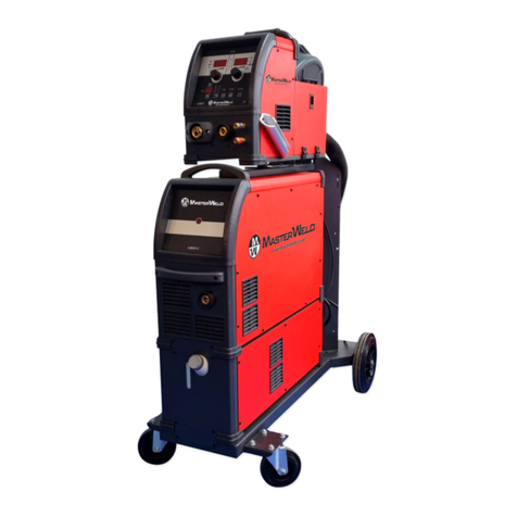
Masterweld 301 PLUS User manual

Cod.006.0001.1319
25/11/2013 v2.7
ENGLISH
Masterweld 301 PLUS
GB
Instruction manual

Cod.006.0001.1319
25/11/2013 v2.7
ENGLISH
Masterweld 301 PLUS
2/28

Masterweld 301 PLUS
Cod.006.0001.1319
25/11/2013 v2.7
ENGLISH
3/28
CONTENTS
1INTRODUCTION .....................................................................................................................................................................................4
2INSTALLATION ......................................................................................................................................................................................5
2.1 CONNECTIONS TO THE ELECTRICAL MAINS NETWORK .................................................................................................................5
2.2 FRONT PANEL........................................................................................................................................................................................5
2.3 REAR PANEL..........................................................................................................................................................................................5
2.4 PREPARING FOR MMA WELDING........................................................................................................................................................6
2.5 PREPARING FOR TIG WELDING ..........................................................................................................................................................7
2.6 PREPARING FOR MIG/MAG WELDING ...............................................................................................................................................8
2.6.1 WIRE SPOOL POSITIONING.......................................................................................................................................................................................... 8
2.6.2 POSITIONING THE WIRE IN THE WIRE FEEDER........................................................................................................................................................ 8
2.6.3 CONNECTIONS TO SOCKETS ...................................................................................................................................................................................... 9
3COMMISSIONING.................................................................................................................................................................................11
3.1 USER INTERFACE ...............................................................................................................................................................................11
3.2 UNIT POWER-UP..................................................................................................................................................................................13
3.3 RESET (LOAD FACTORY SETTINGS) ................................................................................................................................................13
3.4 GAS FLOW ADJUSTMENT...................................................................................................................................................................14
3.5 ALARMS MANAGEMENT .....................................................................................................................................................................14
4WELDING SETTINGS...........................................................................................................................................................................15
4.1 TORCH TRIGGER MODES ..................................................................................................................................................................15
4.2 SELECTION OF THE WELDING MODE AND TORCH TRIGGER PROCEDURE...............................................................................16
4.3 PARAMETERS ACTIVATION ...............................................................................................................................................................16
4.4WELDING PARAMETERS ....................................................................................................................................................................17
4.5 ELECTRODE WELDING (MMA) ...........................................................................................................................................................18
4.5.1 PARAMETERS SETTING: WELDING CURRENT ........................................................................................................................................................ 18
4.5.2 PARAMETERS SETTING: HOT-START....................................................................................................................................................................... 18
4.5.3 PARAMETERS SETTING: ARC FORCE ...................................................................................................................................................................... 18
4.6 DC TIG WELDING.................................................................................................................................................................................18
4.6.1 PARAMETERS SETTING: WELDING CURRENT ........................................................................................................................................................ 18
4.6.2 PARAMETERS SETTING: POST GAS TIME ............................................................................................................................................................... 18
4.7 MIG/MAG WELDING.............................................................................................................................................................................19
4.7.1 PARAMETERS SETTING: MIG/MAG WELDING VOLTAGE ....................................................................................................................................... 19
4.7.2 PARAMETERS SETTING: WIRE FEED RATE............................................................................................................................................................. 19
4.7.3 PARAMETERS SETTING: INDUCTANCE SETTING ................................................................................................................................................... 19
4.7.4 PARAMETERS SETTING: POST GAS TIME ............................................................................................................................................................... 19
4.7.5 PARAMETERS SETTING: SPEED LIMIT ..................................................................................................................................................................... 19
4.7.6 ADJUSTMENT WELDING PARAMETERS PANEL ...................................................................................................................................................... 20
5TECHNICAL DATA...............................................................................................................................................................................21
6SPARE PARTS .....................................................................................................................................................................................23
6.1 WIRE FEED MOTOR ............................................................................................................................................................................25
6.2 WIRE FEEDER ROLLS.........................................................................................................................................................................26
7ELECTRICAL DIAGRAM......................................................................................................................................................................27
7.1 MICROMAG 301 PLUS .........................................................................................................................................................................27

Cod.006.0001.1319
25/11/2013 v2.7
ENGLISH
Masterweld 301 PLUS
4/28
1INTRODUCTION
IMPORTANT!
This handbook must be consigned to the user prior to
installation and commissioning of the unit.
Read the "General prescriptions for use" handbook supplied
separately from this handbook before installing and
commissioning the unit.
The meaning of the symbols in this manual and the associated
precautionary information are given in the "General
prescriptions for use”.
If the "General prescriptions for use" are not present, it is
mandatory to request a replacement copy from the manufacturer
or from your dealer.
Retain these documents for future consultation.
KEY
DANGER!
This pictogram warns of danger of death or serious injury.
WARNING!
This pictogram warns of a risk of injury or damage to property.
CAUTION!
This pictogram warns of a potentially hazardous situation.
INFORMATION
This pictogram gives important information concerning the execution
of the relevant operations.
This symbol identifies an action that occurs automatically as a
result of a previous action.
This symbol identifies additional information or a reference to a
different section of the manual containing the associated
information.
§
This symbol identifies a reference to a chapter of the manual.
NOTES
The figures in this manual are purely guideline and the images may
contain differences with respect to the actual equipment to which they
refer.
INTRODUCTION
The Masterweld 301 PLUS is a compact and heavy duty generator for
MIG/MAG welding.
The reduced weight and compact size allow it to be carried wherever
it is needed. It is designed to give you the maximum power, reliability
and efficiency.
Set up the power source for MMA, MIG/MAG or TIG operation on the
selector switch located on the rear of the panel in the motor
compartment.
Wire reels of up to 200 mm in diameter can be mounted.
Sound alarm. A sound alarm has been provided to protect the power
generator: it blocks the primary inverter in the event that the average
welding current should exceed 310 A for more than 0.6 seconds.
Fan. The fan is turned on only during welding, at the end of the
welding process it remains on for a fixed period of time according to
welding conditions. The fan is nonetheless controlled by specific
thermal sensors that guarantee a correct cooling of the machine.
Accessories that can be connected to the unit:
-Flow meter for adjustment of the gas outlet flow from the welding
torch in litres/minute.
Consult your dealer for an updated list of accessories and the latest
available new products.

Masterweld 301 PLUS
Cod.006.0001.1319
25/11/2013 v2.7
ENGLISH
5/28
2INSTALLATION
DANGER!
Lifting and positioning
Read the warnings highlighted by the following symbols in the
“General prescriptions for use”.
2.1 CONNECTIONS TO THE ELECTRICAL MAINS
NETWORK
The characteristics of the mains power supply to which the equipment
shall be connected are given in the section entitled “Technical data”
on page 21.
The machine can be connected to motorgenerators provided their
voltage is stabilised.
Connect/disconnect the various devices with the machine switched
off.
2.2 FRONT PANEL
1.
Positive pole welding socket.
2.
Negative pole welding socket.
3.
Polarity selector cable.
4.
EURO TORCH welding socket.
2.3 REAR PANEL
1.
Connector for gas feed hose:
cylinder power source
2.
Welding power source ON/OFF switch.
3.
Power cable.
Total length (including internal part): 3,5 m
Number and cross section of wires: 4 x 1,5 mm2
Power plug type: not supplied
4.
Flow meter.
(Purchasing and installing the relative kit).
4
3
3
4
2
1
1
2

Cod.006.0001.1319
25/11/2013 v2.7
ENGLISH
Masterweld 301 PLUS
6/28
Wire feed motor power transformer fuse.
Type: Delayed acting (T)
Amperage: 630 mA
Voltage: 500 V
2.4 PREPARING FOR MMA WELDING
1.
Set the welding power source ON/OFF switch to “O” (unit de-
energized).
2.
Plug the power cable plug into a mains socket outlet.
3.
Choose the electrode based on the type of material and thickness
of the workpiece to be welded.
4.
Insert the electrode in the electrode holder.
5.
Connect the electrode holder cable to the welding socket based on
the polarity requested by the type of electrode used.
6.
Connect the plug of the ground clamp to the welding socket on the
basis of the polarity required.
7.
Connect the earth clamp to the workpiece being processed.
DANGER!
Electric shock hazard!
Read the warnings highlighted by the following symbols in the
“General prescriptions for use”.
8.
Set the welding power source ON/OFF switch to “I” (unit
powered).
9.
Select the following welding mode on the selector located in the
spool compartment: MMA
10.
Set the required welding parameter values on the user interface.
The system is ready to start welding.
Preparing for MMA (polarity to basic electrode)

Masterweld 301 PLUS
Cod.006.0001.1319
25/11/2013 v2.7
ENGLISH
7/28
2.5 PREPARING FOR TIG WELDING
1.
Set the welding power source ON/OFF switch to “O” (unit de-
energized).
2.
Plug the power cable plug into a mains socket outlet.
3.
Connect the gas hose from the welding gas cylinder to the rear
gas socket.
4.
Open the cylinder gas valve.
5.
Connect the TIG torch plug to the EURO TORCH welding socket.
6.
Choose the electrode based on the type of material and thickness
of the workpiece to be welded.
7.
Insert the electrode in the TIG torch.
8.
Connect the plug of the polarity selector cable to the welding
socket on the basis of the polarity required.
9.
Connect the plug of the ground clamp to the welding socket on the
basis of the polarity required.
10.
Connect the earth clamp to the workpiece being processed.
11.
Set the welding power source ON/OFF switch to “I” (unit
powered).
12.
Select the following welding mode on the selector located in the
spool compartment: DC TIG
13.
Open the gas solenoid valve by pressing and releasing the button
.
14.
Use the flow control valve to adjust the flow of gas as required
while the gas is flowing out.
15.
Close the gas solenoid valve by pressing and releasing the button
.
16.
Set the required welding parameter values on the user interface.
The system is ready to start welding.
Preparing for TIG (polarity for tungsten electrode)

Cod.006.0001.1319
25/11/2013 v2.7
ENGLISH
Masterweld 301 PLUS
8/28
2.6 PREPARING FOR MIG/MAG WELDING
2.6.1 WIRE SPOOL POSITIONING
1.
Open the unit side door to gain access to the spool compartment.
2.
Unscrew the cap of the spool holder.
3.
If necessary, fit an adapter for the wire spool.
4.
Choose the wire on the basis of the workpiece thickness and
material type.
5.
Fit the spool in the spool holder, ensuring it is located correctly.
6.
Adjust the spool holder braking system by tightening/loosening the
screw in such a way that the wire feed force is not excessive and
when the spool stops rotating no excess wire is released.
7.
Refit the plug.
2.6.2 POSITIONING THE WIRE IN THE WIRE FEEDER
1.
Lower the wire feeder pressure devices.
2.
Raise the wire feeder pressure arms.
3.
Remove the protective cover.
4.
Check that the feed rolls are suitable for the wire gauge.
(See § 6.2 page 26.)
The diameter of the roll groovemust be compatible with the
diameter of the welding wire.
The roll must be of suitable shape in relation to the composition of
the wire material.
The groove must feature a "U" profile for soft materials (Aluminium
and its alloys, CuSi3).
The groove must be "V" shaped for harder materials (SG2-SG3,
stainless steels).
Rolls with a knurled groove profile are available for flux-cored wire.

Masterweld 301 PLUS
Cod.006.0001.1319
25/11/2013 v2.7
ENGLISH
9/28
5.
Feed the wire between the wire feeder rolls and insert it into the
MIG/MAG TORCH connector plug.
6.
Make sure the wire is located correctly in the roll grooves.
7.
Close the wire feeder pressure arms.
8.
Adjust the pressure system so that the arms press the wire with a
force that does not deform it while also ensuring constant feed rate
without slipping.
9.
Refit the protective cover.
10.
Close the spool compartment door in the side of the unit.
2.6.3 CONNECTIONS TO SOCKETS
1.
Set the welding power source ON/OFF switch to “O” (unit de-
energized).
2.
Plug the power cable plug into a mains socket outlet.
3.
Connect the gas hose from the welding gas cylinder to the relative
socket.
4.
Open the cylinder gas valve.
5.
Connect the MIG/MAG torch plug to the EURO TORCH welding
socket.
6.
Connect the plug of the ground clamp to the welding socket on the
basis of the polarity required.
7.
Connect the plug of the polarity selector cable to the welding
socket on the basis of the polarity required.
8.
Connect the earth clamp to the workpiece being processed.
9.
Set the welding power source ON/OFF switch to “I” (unit
powered).
10.
Select the following welding mode on the selector located in the
spool compartment: MIG/MAG
11.
Feed the wire through the torch until it protrudes from the tip,
pressing button on the unit's user interface.
The insertion speed is 2 m/min for 3 seconds, subsequently
increasing to 15 m/min. When the button is released wire feed is
interrupted.
This function produces a slower feed rate and hence greater
precision when inserting the wire when it enters the torch nozzle.
12.
Select the torch trigger procedure on the user interface.
13.
Open the gas solenoid valve by pressing and releasing the button
.
14.
Use the flow control valve to adjust the flow of gas as required
while the gas is flowing out.
15.
Close the gas solenoid valve by pressing and releasing the button
.
16.
Set the required welding parameter values on the user interface.
The system is ready to start welding.

Cod.006.0001.1319
25/11/2013 v2.7
ENGLISH
Masterweld 301 PLUS
10/28
Preparing for MIG/MAG
The above diagram shows the MIG welding torch to be the
Masterweld MW300. Although lightweight this torch has a 300 amp
bicox cable, designed to withstand the amperage capacity and the
OCV (Open Circuit Voltage) of the machine. We recommend the use
of this torch best arc characteristics and consumable life.

Masterweld 301 PLUS
Cod.006.0001.1319
25/11/2013 v2.7
ENGLISH
11/28
3COMMISSIONING
3.1 USER INTERFACE
CODE
SYMBOL
DESCRIPTION
L1
This LED illuminates to show an anomaly in the operating conditions.
See § 3.5 ALARMS MANAGEMENT page 14.
L2
Illumination of this LED indicates the display of the average voltage and current value measured during the final
moments of welding.
The value appears on the following displays: D1-D2
L3
This LED illuminates to confirm the presence of power on the output sockets.
L4
Illuminates to show a value in the following unit of measurement: VOLTS
L5
Illuminates to show a value in the following unit of measurement: METRES PER MINUTE
L6
Illuminates to show a value in the following unit of measurement: AMPERES
L10
Illumination shows that the following function has been activated: 2 stroke procedure.
L11
Illumination shows that the following function has been activated: 4 stroke procedure.
D1
Parameters/functions setting
MIG/MAG mode: the display shows the programmed wire feed rate.
MMA mode: the display shows the ampere value set for welding.
TIG Mode: the display shows the ampere value set for welding.
Welding
The display shows the effective amperes value during welding.
Menu function
The display shows the acronym of the parameter or function to be adjusted.
D2
Parameters/functions setting
Manual MIG/MAG mode: the display shows the programmed voltage.
MMA mode: The display shows “MMA“.
TIG Mode: The display shows “tIG“.
Welding
The display shows the effective voltage value during welding.
Menu function
The display shows the value of the parameter or function to be adjusted.

Cod.006.0001.1319
25/11/2013 v2.7
ENGLISH
Masterweld 301 PLUS
12/28
CODE
SYMBOL
DESCRIPTION
S1
This button opens the gas solenoid valve to fill the circuit and calibrate the pressure with the regulator on the gas
cylinder.
POST-GAS adjustment
Hold down the button for 3 seconds to open the menu. (See § 4.6.2 page 18.)
S2
MIG/MAG mode: this button activates wire feed to insert it through the MIG/MAG torch.
SPEED LIMIT adjustment
Hold down the button for 3 seconds to open the menu. (See § 4.7.5 page 19.)
S3
MIG/MAG mode: this button selects the torch trigger procedure.
HOT-START adjustment
Hold down the button for 3 seconds to open the menu. (See § 4.5.2 page 18.)
POT1
MIG/MAG mode: the potentiometer sets the inductance value.
MMA mode: the potentiometer sets the value of the following parameter: ARC FORCE
POT2
Parameters/functions setting
MIG/MAG mode: the potentiometer sets the value of the following parameter: WIRE FEED RATE
Menu function
The potentiometer selects the function or parameter to be adjusted.
POT3
Parameters/functions setting
MIG/MAG mode: the potentiometer sets the welding mode.
Menu function
the potentiometer sets the value of the selected function or parameter.
SEL1
The selector sets the welding mode.

Masterweld 301 PLUS
Cod.006.0001.1319
25/11/2013 v2.7
ENGLISH
13/28
3.2 UNIT POWER-UP
Set the welding power source ON/OFF switch to “I” to switch on the unit.
AL.HEA.
The message appears for a few seconds on the following displays: D1-D2
First power-up or power-ups following a RESET procedure
The welding power source sets up for welding with the factory presets.
Subsequent power-ups
The welding power source sets up for welding in the latest stable welding configuration that was active at the time of power-off.
3.3 RESET (LOAD FACTORY SETTINGS)
The reset procedure involves complete restoration of the default values, parameters and memory settings set in the factory.
All memory locations will be reset and hence all your personal welding settings will be lost!
The reset procedure is useful in the following cases:
-Too many changes made to the welding parameters so user finds it difficult to restore defaults.
-Unidentified software problems that prevent the welding power source from functioning correctly.
Set the welding power source ON/OFF switch to “O” to switch the unit off.
S1
S3
Hold down both buttons simultaneously.
Set the welding power source ON/OFF switch to “I” to switch on the unit.
SIMULTANEOUS ACTIONS
FAC
The message appears on the following displays: D2
Release buttons.

Cod.006.0001.1319
25/11/2013 v2.7
ENGLISH
Masterweld 301 PLUS
14/28
3.4 GAS FLOW ADJUSTMENT
When the unit is powered on the solenoid valve opens for 1 second.
This serves to fill the gas circuit.
S1
Open the gas solenoid valve by pressing and releasing the button.
Adjust the pressure of gas flowing from the torch by means of the flow meter connected to the gas cylinder.
S1
Close the gas solenoid valve by pressing and releasing the button.
The solenoid valve closes automatically after 15 seconds.
3.5 ALARMS MANAGEMENT
This LED illuminates if an incorrect operating condition occurs.
An alarm message appears on the following display: D1-D2
Tab. 1 - Alarm messages
MESSAGE
MEANING
EVENT
CHECKS
AL. HEA.
Overheating alarm
Indicates tripping of the welding power
source thermal protection.
All functions disabled.
Exceptions:
-cooling fan.
Leave the unit running so that the
overheated components cool as rapidly
as possible.
When the unit has cooled, the welding
power source will reset automatically.
-Make sure that the power required by
the welding process is lower than the
maximum rated power output.
-Check that the operating conditions
are in compliance with the welding
power source data plate
specifications.
-Check for the presence of adequate
air circulation around the welding
power source.
AL. Cur.
Overcurrent alarm
Indicates tripping of the welding power
source current surge protection.
All functions disabled.
Exceptions:
-cooling fan.
An audible signal will sound (buzzer).
Muting the audible signal:
-in torch trigger procedure 2T, release
the torch trigger.
-in torch trigger procedure 4T the
alarm mutes automatically after 5
seconds.
Exit the alarm state by performing one of
the following actions:
-press any button.
-switch the power source off.
-Check that the programmed arc
voltage value is not too high in relation
to the thickness of the work to be
welded.

Masterweld 301 PLUS
Cod.006.0001.1319
25/11/2013 v2.7
ENGLISH
15/28
4WELDING SETTINGS
4.1 TORCH TRIGGER MODES
2 STROKE LIFT-ARC TIG WELDING (2T)
1.
Touch the workpiece with the torch electrode.
2.
Press (1T) and keep the torch trigger pressed.
3.
Slowly lift the torch to strike the arc.
The welding current reaches the preset value, by way of a up slope time, if programmed.
4.
Release (2T) the trigger to start the weld completion procedure.
The current reaches the end current value in the time set in the down slope time parameter.
The arc is extinguished.
Gas delivery continues for the time set in the post gas parameter.
4 STROKE LIFT-ARC TIG WELDING (4T)
1.
Touch the workpiece with the torch electrode.
2.
Press (1T) and release (2T) the torch trigger.
3.
Slowly lift the torch to strike the arc.
The welding current reaches the preset value, by way of a up slope time, if programmed.
4.
Press (3T) the trigger and keep it pressed to start the weld completion procedure.
The current reaches the end current value in the time set in the down slope time parameter.
The arc continues and the current output will be the value set in the end current parameter.
In these conditions the weld pool can be closed (crater filler current).
5.
Release (4T) the trigger to extinguish the arc.
Gas delivery continues for the time set in the post gas parameter.
2 STROKE MIG/MAG WELDING (2T)
1.
Bring the torch up to the workpiece.
2.
Press (1T) and keep the torch trigger pressed.
The wire advances at the approach speed until making contact with the work.
The arc strikes and the wire feeder accelerates to the set feed rate value.
3.
Release (2T) the trigger to start the weld completion procedure.
Gas flow continues for the time set in the post gas parameter (adjustable time).
4 STROKE MIG/MAG WELDING (4T)
1.
Bring the torch up to the workpiece.
2.
Press (1T) and release (2T) the torch trigger.
The wire advances at the approach speed until making contact with the work.
The arc strikes and the wire feeder accelerates to the set feed rate value.
3.
Press (3T) the trigger to start the weld completion procedure.
Gas flow continues until the torch trigger is released.
4.
Release (4T) the torch trigger to start the post gas procedure (adjustable time).

Cod.006.0001.1319
25/11/2013 v2.7
ENGLISH
Masterweld 301 PLUS
16/28
4.2 SELECTION OF THE WELDING MODE AND TORCH TRIGGER PROCEDURE
SEL1
Use this selector to select one of the following welding modes.
S3
Use this button to select one of the following torch trigger procedures.
PROCEDURE
MODE
2 STROKE
4 STROKE
MMA
✓
✓
TIG DC CONTINUOUS
✓
✓
MIG/MAG
4.3 PARAMETERS ACTIVATION
The welding parameters are available in accordance with the selected welding mode and procedure.
The table shows the settings required to enable each parameter.
MODE
PROCEDURE
PARAMETER
WELDING CURRENT
✓
✓
✓
✓
✓
HOT-START
✓
ARC FORCE
✓
POST GAS TIME
✓
✓
✓
✓
MIG/MAG WELDING VOLTAGE
✓
✓
WIRE FEED RATE
✓
✓
SPEED LIMIT
INDUCTANCE
✓
✓
SOFT-ARC
✓
✓
BURN-BACK
✓
✓
SOFT-START
✓
✓
MOTOR SLOPE
✓
✓

Masterweld 301 PLUS
Cod.006.0001.1319
25/11/2013 v2.7
ENGLISH
17/28
4.4 WELDING PARAMETERS
WELDING CURRENT
Output current value during welding.
HOT-START
This parameter aids electrode melting at the time of arc striking.
Consequences of a higher value:
-Easier arc strike.
-Increased spatter at welding start.
-Increase of strike area.
Consequences of a lower value:
-More difficult arc strike.
-Less spatter at welding start.
-Smaller strike area.
ARC FORCE
This parameter helps to avoid electrode sticking during welding.
During electrode fusion low conductivity parts of the coating become
detached and tend to become interposed between the electrode tip as
it is fusing and the workpiece. This condition results in an interruption
of the arc. In addition, it may occur that the electrode comes into
contact with the workpiece creating a short circuit and consequent
quenching of the arc. To avoid arc quenching the power source
therefore delivers instantaneous peak currents in correspondence
with preset arc voltage thresholds.
Consequences of a higher value:
-Fluidity during welding.
-Welding arc stability.
-Greater electrode fusion in workpiece.
-More welding spatter.
Consequences of a lower value:
-The arc is extinguished more easily.
-Less welding spatter.
POST GAS TIME
Time of post gas delivery when the welding arc is extinguished.
This is useful when welding at high current values or with materials
that oxidise readily to cool the weld pool in an uncontaminated
atmosphere.
In the absence of specific requirements the value should generally be
kept low.
Consequences of a higher value:
-More effective pickling (improved appearance of workpiece at the
end of the welding pass).
-Higher gas consumption.
Consequences of a lower value:
-Lower gas consumption.
-Oxidation of electrode tip (more difficult arc strike).
MIG/MAG WELDING VOLTAGE
The parameter sets the welding voltage in MIG/MAG mode.
WIRE FEED RATE
The parameter sets the output wire feed rate.
The maximum speed setting can be limited by adjusting the "speed
limit" parameter.
SPEED LIMIT
The parameter limits maximum motor speed, which is adjustable by
means of the potentiometer.
INDUCTANCE
Consequences of a higher value:
-"Softer welding".
-Less spatter.
-Less positive starting.
Consequences of a lower value:
-"Harder welding".
-More spatter.
-More reliable starting.
SOFT-ARC
A parameter that optimises the welding of aluminium and stainless
steel with thin thicknesses.
BURN-BACK
The burn back value is associated with the quantity of wire that is
burnt at the end of the welding procedure.
Consequences of a higher value:
-Wire significantly retracted into the torch nozzle.
Consequences of a lower value:
-Stick-out at welding start is longer.
SOFT-START
The soft start is the wire approach speed to the workpiece.
The value is expressed as a percentage of the set feed rate.
Consequences of a lower value:
-The start of welding is "softer".
Consequences of a higher value:
-The welding start may prove difficult.
MOTOR SLOPE
Time required to switch from SOFT START speed to welding speed.

Cod.006.0001.1319
25/11/2013 v2.7
ENGLISH
Masterweld 301 PLUS
18/28
4.5 ELECTRODE WELDING (MMA)
SEL1
Select the following welding mode on the selector located in the spool compartment: MMA
MMA
The message appears on the following displays: D2
4.5.1 PARAMETERS SETTING: WELDING CURRENT
E1
Using the potentiometer, edit the value of the parameter.
The value appears on the following display: D1
PARAMETER
MIN
DEFAULT
MAX
WELDING CURRENT
10 A
80 A
250 A
4.5.2 PARAMETERS SETTING: HOT-START
S3
Hold down the button for 3 seconds to open the menu.
The acronym relative to the setting to be edited appears on the following displays: D1
The value relative to the selected setting appears on the following displays: D2
POT3
Using the potentiometer, edit the value of the selected setting.
Press any button to save the setting and quit the menu.
ACRONYM
PARAMETER
MIN
DEFAULT
MAX
H.S.
HOT-START
0 %
50 %
100 %
4.5.3 PARAMETERS SETTING: ARC FORCE
POT3
Using the potentiometer, edit the value of the setting.
PARAMETER
MIN
DEFAULT
MAX
ARC FORCE
0 %
- %
200 %
4.6 DC TIG WELDING
SEL1
Select the following welding mode on the selector located in the spool compartment: DC TIG
tIG
The message appears on the following displays: D2
4.6.1 PARAMETERS SETTING: WELDING CURRENT
E1
Using the potentiometer, edit the value of the parameter.
The value appears on the following display: D1
PARAMETER
MIN
DEFAULT
MAX
WELDING CURRENT
10 A
80 A
250 A
4.6.2 PARAMETERS SETTING: POST GAS TIME
S1
Hold down the button for 3 seconds to open the menu.
The acronym relative to the setting to be edited appears on the following displays: D1
The value relative to the selected setting appears on the following displays: D2
POT3
Using the potentiometer, edit the value of the selected setting.
Press any button to save the setting and quit the menu.
ACRONYM
PARAMETER
MIN
DEFAULT
MAX
Po.G.
POST GAS TIME
0.0 s
3.0 s
10.0 s

Masterweld 301 PLUS
Cod.006.0001.1319
25/11/2013 v2.7
ENGLISH
19/28
4.7 MIG/MAG WELDING
SEL1
Select the following welding mode on the selector located in the spool compartment: MIG/MAG
4.7.1 PARAMETERS SETTING: MIG/MAG WELDING VOLTAGE
POT3
Using the potentiometer, edit the value of the parameter.
The value is saved automatically.
PARAMETER
MIN
DEFAULT
MAX
MIG/MAG WELDING VOLTAGE
10.0 V
-
40.0 V
4.7.2 PARAMETERS SETTING: WIRE FEED RATE
POT2
Using the potentiometer, edit the value of the parameter.
The value is saved automatically.
PARAMETER
MIN
DEFAULT
MAX
WIRE FEED RATE
1.0 m/min
20.0 m/min
4.7.3 PARAMETERS SETTING: INDUCTANCE SETTING
POT1
Using the potentiometer, edit the value of the parameter.
4.7.4 PARAMETERS SETTING: POST GAS TIME
S1
Hold down the button for 3 seconds to open the menu.
The acronym relative to the setting to be edited appears on the following displays: D1
The value relative to the selected setting appears on the following displays: D2
POT3
Using the potentiometer, edit the value of the selected setting.
Press any button to save the setting and quit the menu.
ACRONYM
PARAMETER
MIN
DEFAULT
MAX
Po.G.
POST GAS TIME
0.0 s
3.0 s
10.0 s
4.7.5 PARAMETERS SETTING: SPEED LIMIT
Set the welding power source ON/OFF switch to “O” to switch the unit off.
S2
Hold down the button.
Set the welding power source ON/OFF switch to “I” to switch on the unit.
SIMULTANEOUS ACTIONS
The acronym relative to the setting to be edited appears on the following displays: D1
The value relative to the selected setting appears on the following displays: D2
POT3
Using the potentiometer, edit the value of the selected setting.
Press any button to save the setting and quit the menu.
ACRONYM
PARAMETER
MIN
DEFAULT
MAX
SP.L.
SPEED LIMIT
1.0 m/min
20.0 m/min
20.0 m/min

Cod.006.0001.1319
25/11/2013 v2.7
ENGLISH
Masterweld 301 PLUS
20/28
4.7.6 ADJUSTMENT WELDING PARAMETERS PANEL
The picture shows the adjustment panel of MIG/MAG welding
parameters, accessible by opening the wire feeding unit door.
If the panel is not enabled, the microprocessor automatically assigns
the default value to the parameters.
PARAMETER
MIN
DEFAULT
MAX
SOFT-ARC
10 A
30 A
50 A
BURN-BACK
0 ms
30 ms
100 ms
SOFT-START
10 %
30 %
100 %
MOTOR SLOPE
0 ms
0 ms
200 ms
Table of contents
Other Masterweld Welding System manuals
Popular Welding System manuals by other brands

Rothenberger
Rothenberger ROWELD P 160 Saniline Instructions for use

Migatronic
Migatronic SIGMA GALAXY Log book and instructions for use

Kemppi
Kemppi X5 FastMig Series operating manual

Kemppi
Kemppi MTP 350 operating manual

GYS
GYS WCU 039490 Translation of the original instructions

Lincoln Electric
Lincoln Electric INVERTEC IM465-B Operator's manual

Eastwood
Eastwood VERSA-CUT 60 Assembly & operating instructions

Hanshen
Hanshen FKR350 Operation manual

Lincoln Electric
Lincoln Electric IDEALARC SP-255 Operator's manual

STAMOS
STAMOS SWS03 user manual

Hobart
Hobart H200L4-15 owner's manual

SincoSald
SincoSald NOVASTICK 163 PFC Instruction manual for installation, use and maintenance