CenterLine VeriFast LVDT User manual

connecting needs with capabilities
VeriFast
TM
LVDT
User Manual
Ver. 1.15 – September 2018
FDP-VFA-LVD-UM-EL-1.15-0918

Product Sales and Support
The VeriFast™LVDT is a component of a resistance welding system manufactured by:
For all replacement parts and service inquiries, contact CenterLine’s inside sales department:
Telephone: 519.734.8330
Toll Free in Canada & US: 1.800.268.8330
Fax: 519.734.2006
Email: info@cntrline.com
Visit www.cntrline.com for detailed information on any of the facilities listed below.
Manufacturing Facilities
Regional Sales/Service
Offices
Machinery Division
415 Morton Drive
Windsor ON N9J 3T8
Canada
CAN. 519.734.8464
U.S. 313.962.1448
Toll Free: 1.800.820.6977
Electrodes Division
595 Morton Drive
Windsor ON N9J 3T8
Canada
CAN. 519.734.6886
U.S. 313.961.4080
Toll Free: 1.800.249.6886
CenterLine Welding Products
1985 Ring Drive
Troy MI 48083
USA
U.S. 877.574.5400
Automation Components Division
655 Morton Drive
Windsor ON N9J 3T9
Canada
CAN. 519.734.8330
U.S. 313.961.3731
Toll Free: 1.800.268.8330
Supersonic Spray Technologies
Div.
655 Morton Drive
Windsor ON N9J 3T9
Canada
CAN. 519.734.8464
CenterLine SE USA
3409 Lorna Lane
Hoover, AL 35216
USA
U.S. 734.260.2845
CenterLine De Mexico S.
de R.L. de C.V
Av. La Noria #110
Parque Industrial Querétaro,
Santiago de Querétaro, Qro
Mexico CP 76220
MX. +52.442.240.9255
CenterLine Brazil Solda e
Automação Ltda
Rod. BR 280 KM 43 n°501,
Bairro Poço Grande, Cidade de
Guaramirim, Santa Catarina, Brazil
P.O.Box: n°57
Brazil Cep: 89270-000
BR. . (General)+ 55 47 3085 – 8300
(Sales) + 55 47 3085 – 8301
(Engin.) + 55 47 3085 – 8307
(Project Mgmt) + 55 47 3085 – 8308
CenterLine De Mexico S. de R.L. de C.V-
Hermosillo Region
Carr. La Colorada Km 4.5
Col. Parque Industrial,
Hermosillo Sonora Mexico
MX. +52.442.240.9255
CenterLine-Seubert GmbH.
Formerstraße 7,
D-35236 Breidenbach,
Germany
DE. +49.6465.911.20
Email: cls@cntrline.com
CenterLine India Pvt Ltd.
37-B, Udyog Vihar,
Phase – V
Gurgaon 122016
Haryana, India
IN. +91.124.4278267
CenterLine Romania SRL
Strada Izvorul Rece, Nr. 7
Brasov, Romania, 500.097
Tel. +40.268.415004
Mobil : +40.268.415004
Email: victor.fratu@cntrline.com
CenterLine Welding Technologies
(Guangzhou) Co. Ltd.
68 Huangang Av., Huadu District,
510800
Guangzhou, China
CN. +86-20-6635-6533

Disclaimer
This document is provided for informational purposes only. Due to the variety of uses for the product illustrated in this
publication, those responsible for the application and use of this product must satisfy themselves that each
application and use of the product meets all applicable laws, regulation codes, and standards. Users of this document
should consult applicable federal, state, and local laws and regulations. CenterLine (Windsor) Limited does not, by
the publication of this document, intend to urge action that is not in compliance with applicable laws, and this
document may not be construed as doing so. CenterLine (Windsor) Limited has made every effort to ensure the
accuracy and completeness of this document; however, because ongoing efforts are made to continually improve the
capabilities of our products, we cannot guarantee the accuracy of the contents of this document. We disclaim liability
for errors, omissions, or future changes herein.
In no event will CenterLine (Windsor) Limited be responsible or liable to any party for any personal injury, property or
other damages of any nature whatsoever, whether special, direct, indirect, incidental, consequential or compensatory,
directly or indirectly resulting from the publication, use of, or reliance on this document, and also from the use of the
equipment described herein.
In issuing and making this document available, CenterLine (Windsor) Limited is not undertaking to render
professional or other services for or on behalf of any person or entity. Nor is CenterLine (Windsor) Limited
undertaking to perform any duty owed by any person or entity to someone else. Anyone using this document should
rely on his or her own independent judgment or, as appropriate, seek the advice of a competent professional in
determining the exercise of reasonable care in any given circumstances.
The illustrations, explanations, charts, and layout examples shown in this publication are intended solely for purposes
of example. Since there are many variables and requirements associated with any particular installation, CenterLine
(Windsor) Limited does not assume responsibility of liability (including intellectual property liability) for actual use
based upon the information given in this publication.
Reproduction of the contents of this copyrighted publication, in whole or part, without written permission of CenterLine
(Windsor) Limited, is prohibited.
© Copyright 2018, CenterLine (Windsor) Ltd. All rights reserved

This page is left blank intentionally.

VeriFastTM LVDT – User Manual – FDP-VFA-LVD-UM-EL-1.15-0918 5
Table of Contents
Product Sales and Support................................................................................................................................2
Table of Contents................................................................................................................................................5
Preface .................................................................................................................................................................7
Who Should Use This Manual......................................................................................................................7
Purpose of This Manual................................................................................................................................7
Conventions Used in This Manual................................................................................................................7
Terminology and Symbols Used Throughout This Manual...........................................................................8
Safety Information...............................................................................................................................................9
Important Safety Information ........................................................................................................................9
Handling the VeriFast LVDT.........................................................................................................................9
Potential Hazards Related to VeriFast LVDT.............................................................................................10
Personal Protective Equipment..................................................................................................................10
Equipment and Process Overview ..................................................................................................................11
Intended Use of Equipment........................................................................................................................11
VeriFast LVDT Main Components..............................................................................................................12
VeriFast LVDT Configurations....................................................................................................................13
Base Mount Styles (Except SXZR)....................................................................................................13
SYVR Extended Base Mount Style....................................................................................................14
SXZR Base Mount Style ....................................................................................................................14
Tapered and Threaded Mount Styles ................................................................................................15
Clamp Mount Style.............................................................................................................................15
Part Ordering Information...........................................................................................................................16
Required Services.............................................................................................................................................17
Control Requirements.................................................................................................................................17
Electrical Requirements..............................................................................................................................17
Pneumatic Supply Requirements ...............................................................................................................17
Water Supply Requirements.......................................................................................................................18
Water Temperature............................................................................................................................18
Water Pressure..................................................................................................................................18
Water Flow.........................................................................................................................................18
Installation Guidelines......................................................................................................................................19
Important Safety Information ......................................................................................................................19
Pre-Installation Tips and Requirements .....................................................................................................19
Mounting the Base Mount Electrode ..........................................................................................................20

6 VeriFastTM LVDT – User Manual – FDP-VFA-LVD-UM-EL-1.15-0918
Mounting the Signal Conditioner ................................................................................................................21
Wiring the VeriFast LVDT and Signal Conditioner .....................................................................................21
Connecting the Signal Conditioner to the 5-pin Shielded Cable and PLC.........................................22
Synchronizing Multiple Signal Conditioners.......................................................................................22
Connecting the 5-pin Shielded Cable/Connector to the VeriFast LVDT Electrode............................22
Learning about the VeriFast LVDT Signal Conditioner...............................................................................23
Operation of LED Indicators...............................................................................................................23
Re-Calibrating the Signal Conditioner (If necessary).........................................................................24
Determining Effective Resolution.......................................................................................................24
Establishing the Pneumatic Service Connection........................................................................................25
Pneumatic Connection Diagram for LVDT Weld Bodies with Retractable Pin (Not applicable to
Clamp Mount Assemblies).................................................................................................................26
Pneumatic Connection Diagram for LVDT Weld Bodies Used in Ring Weld or Clinching Applications
(Not applicable to Clamp Mount Assemblies)....................................................................................27
Pneumatic Connection Diagram for LVDT Weld Bodies with Non-Retractable Pin (Not applicable to
Clamp Mount Assemblies).................................................................................................................27
Pneumatic Connection Diagram for LVDT Clamp Mount Weld Bodies with Retractable Pin............28
Pneumatic Connection Diagram for LVDT Clamp Mount Weld Bodies with Non-Retractable Pin ....28
Maintenance ......................................................................................................................................................29
Important Safety Information ......................................................................................................................29
Special Caution ..........................................................................................................................................29
Servicingthe LVDTElectrode Assembly forBase (Except SXZR), Extended Base,Tapered, and Threaded Mount
Styles...........................................................................................................................................................29
Servicingthe LVDTElectrode Assembly forSXZR Base Mount Style ................................................................33
Servicing the LVDT Electrode Assembly for Clamp Mount Style........................................................................37
Working Area Maintenance........................................................................................................................40
Cleaning the Equipment.............................................................................................................................40
Troubleshooting Quick Guide..........................................................................................................................41
Important Safety Information ......................................................................................................................41
Troubleshooting Instructions ......................................................................................................................41
Decommissioning .............................................................................................................................................43
Preparing for Storage .................................................................................................................................43
Appendix A – Signal Conditioner Specifications...........................................................................................44
Complete Signal Conditioner Electrical Connections.................................................................................44
Signal Conditioner Specifications...............................................................................................................44
Index.......................................................................................................................................................... Index-1
VeriFastTM LVDT – User Manual – FDP-VFA-LVD-UM-EL-1.15-0918 7
Preface
Who Should Use This Manual
Any person installing, using, or maintaining a VeriFast LVDT unit should use this manual.
Purpose of This Manual
This manual describes the function, installation and necessary operating instructions for the
proper use of the standard VeriFast LVDT. For assistance with any other customized products
or non-standard applications, additional support is available from CenterLine. Please refer to the
inside front cover of this manual for CenterLine contact information.
To prevent potentially serious or fatal injury, this manual must be
read and understood in its entirety prior to installation, operation, or
maintenance of any VeriFast LVDT.
While every effort has been made to ensure that the product
descriptions, procedures, and installation requirements included in
this publication are accurate at the time of printing, CenterLine
reserves the right to make product changes that might not be
reflected in this document.
Should you require additional information, please contact
CenterLine, its agents, or distributors for assistance.
Conventions Used in This Manual
This manual uses the following notations:
•Bulleted lists – such as this one – provide information, not procedural steps.
•Numbered lists provide sequential steps to follow or hierarchical information.
•When we refer you to a different section of this manual or to other documentation, the
section, chapter, and publication title appear in italics.
8 VeriFastTM LVDT – User Manual – FDP-VFA-LVD-UM-EL-1.15-0918
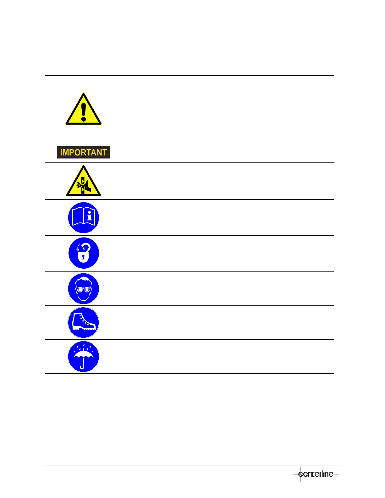
Terminology and Symbols Used Throughout This Manual
Throughout this manual, all the safety related notes have been identified by the following terms:
This symbol relates information about practices or situations that can
lead to personal injury or death, property damage, or economic loss.
Attention statements help you to:
•Identify a hazard.
•Avoid a hazard.
•Recognize the consequences.
This symbol relates information that is critical for a successful
application and understanding of the product.
This symbol indicates that serious hazards can occur due to pinch
points.
This symbol indicates that you should read and understand the User
Manual and all other applicable instructions before operating the
equipment.
This symbol indicates that the equipment must be disconnected
from all sources of power and put in the lockout state.
This symbol indicates that eye protection must be worn as a
protection against dust, flying objects and particles.
This symbol indicates that appropriate safety shoes must be worn in
order to avoid injuries from exposure to working environment.
This symbol indicates that the equipment must be kept dry,
protected from excessive humidity and rain.

VeriFastTM LVDT – User Manual – FDP-VFA-LVD-UM-EL-1.15-0918 9
Safety Information
Important Safety Information
The VeriFast LVDT is used in conjunction with welding equipment and machinery. Therefore, as
a supplement to the safety information offered in this manual for the VeriFast LVDT, all the
safety considerations that pertain to the equipment used in conjunction with the VeriFast LVDT
still apply and must be followed thoroughly.
Furthermore, all the existing plant safety regulations and other safety instructions from suppliers
whose components are used with or around the VeriFast LVDT must be followed accordingly.
Any instructions contained in this manual that directly conflict with any other known safety
procedures should be brought to CenterLine’s immediate attention for clarification.
•Equipment is not to be modified, adapted, or changed without
consulting the relevant sections of this manual or the
manufacturer (please refer to the inside front cover of this manual
for CenterLine contact information).
•Before any installation, maintenance, or repair work is started, all
sources of energy should be removed from the equipment using
p
roper LOCKOUT procedures for electrical, pneumatic, and water
services.
•Pneumatic and cooling water lines represent potential hazards.
Ensure all air and water lines are properly connected and
secured prior to turning ON these services.
Handling the VeriFast LVDT
In order to prevent potentially serious personal injury, the VeriFast LVDT should be handled,
installed, and operated according to the guidelines outlined in this document. Failure to follow
the guidelines set forth here will bear unexpected and potentially dangerous results.

10 VeriFastTM LVDT – User Manual – FDP-VFA-LVD-UM-EL-1.15-0918
Potential Hazards Related to VeriFast LVDT
The VeriFast LVDT system has no specific hazards related to it. However, as the VeriFast
LVDT is used in conjunction with other equipment such as welding equipment and machinery,
robot, air supply, etc., the user should be aware of the warnings, hazards, and precautions
related to the use of the equipment as a whole.
Lockout Equipment
•Before starting to install the VeriFast components on the welding
equipment, ensure that the equipment is disconnected from all
sources of power and is in the lockout state.
•Before turning ON the equipment, make sure all components are
assembled properly.
•Before removing the VeriFast from the welding equipment, make
sure the equipment is turned OFF and is in the lockout state.
Personal Protective Equipment
When handling, installing, and operating VeriFast equipment, the following items are
recommended in addition to standard safety equipment:
Adequate eye protection, to prevent exposure of the eyes against
flying objects, and particles.
Appropriate safety shoes, to protect feet against heavy loads, cuts,
flying objects and electrical hazards.

VeriFastTM LVDT – User Manual – FDP-VFA-LVD-UM-EL-1.15-0918 11
Equipment and Process Overview
Intended Use of Equipment
The VeriFast LVDT is a component of a resistance welding system. When properly installed in
conjunction with resistance weld control equipment and used within the system’s specification
limits, the VeriFast LVDT is used to verify the presence and orientation of fasteners or materials.
The VeriFast LVDT is not intended for any other use.
The VeriFast LVDT sensor signal is calibrated to measure and output the position of the
fastener (nut or stud) weld pin in various stages of travel. The values of this signal are then
compared to peripherally programmed set point values (with tolerances). Results that do not
match the set point values can trigger either an interruption in the cycle, or a warning message
indicating that the process has fallen outside the set value. These occurrences can indicate a
potential part quality issue.
The set point values may indicate:
•Weld Pin Extended Position (System ready to load part and fastener)
•Weld Proceed (Presence and Correct Fastener Orientation)
•Weld Complete (Nut Welded)
•Nut is Upside Down
•No Fastener Detected
•No Part Detected
•Weld Pin Retracted Position (Allowing safe part removal by robot or other process operations)
The VeriFast LVDT system has the ability to detect differences as small as (0.02 mm) 0.0009".
However, actual performance is dependent on the effective resolution of the control system to
which it is integrated. For more information refer to section Determining Effective Resolution on
page 24.
The following example shows a nut application. It demonstrates the difference between correct
fastener orientation, and other error conditions.

12 VeriFastTM LVDT – User Manual – FDP-VFA-LVD-UM-EL-1.15-0918
Figure 1 – Nut Detection and Orientation
VeriFast LVDT Main Components
The VeriFast LVDT has a robust construction that allows for fast and easy component changes.
A standard configuration of VeriFast LVDT is illustrated in Figure 2 below.
Figure 2 – VeriFast LVDT Configuration


16 VeriFastTM LVDT – User Manual – FDP-VFA-LVD-UM-EL-1.15-0918
Part Ordering Information
Each VeriFast LVDT component (e.g., weld body, signal conditioner) is marked with labels
providing information about your specific configuration. When ordering a replacement
component, please check your own equipment and have that specific part number readily
available.
If you need to order other components, please refer to the detailed VeriFast LVDT Part Ordering
Instructions brochure available from CenterLine.
For optimal equipment performance and full warranty support,
CenterLine consumables must be used.

VeriFastTM LVDT – User Manual – FDP-VFA-LVD-UM-EL-1.15-0918 17
Required Services
When establishing the services (electrical, pneumatic, water) to your
VeriFast LVDT, all service requirements illustrated in the current
section must be satisfied.
Control Requirements
Minimum recommended control connection requirements are as follows:
An analog input is required to receive the VeriFast LVDT system signal and a 15 bit resolution is
recommended to achieve ideal operating performance. Actual performance is dependent on the
effective resolution of the control system to which the VeriFast LVDT system is integrated. For
more information refer to Determining Effective Resolution on page 24.
Electrical Requirements
The VeriFast LVDT power supply requirements are as follows:
•Volts: 24 VDC
•Amps: 90 mA.
For more electrical specifications, please see the values listed in the Appendix A – Signal
Conditioner Specifications section starting on page 44.
Pneumatic Supply Requirements
The operating performance of the VeriFast LVDT is closely tied to the quality and configuration
of the air supply system.
•Tubing: M6 (3/8ʺ) weld spatter resistant
•Ideal operating pressure: 3.5 bar (50 psi)
•Air shall be filtered and non-lubricated. The air must be clean, dry, and free of
contaminants. A pneumatic filter with 5 micron element size is recommended for air
cleanliness.
•For installation guidelines, please refer to the Establishing the Pneumatic Service
Connection section starting on page 24.

18 VeriFastTM LVDT – User Manual – FDP-VFA-LVD-UM-EL-1.15-0918
Water Supply Requirements
The welding equipment requires water cooling to dissipate the heat generated in the resistance
welding process. The operating performance of the equipment is closely tied to the quality and
configuration of the water supply system.
•Improper water hookup will result in insufficient cooling,
which may cause severe equipment damage or personal
injury. Always ensure proper safety precautions.
•After the cooling circuit is connected, ensure that there are
no kinks in any of the lines, and all fittings have been
tightened and checked for leaks.
The requirements for the cooling water are as follows:
Water Temperature
•Water temperatures between 24°C to 30°C (75°F to 85°F) are recommended.
•The water temperature should not exceed 30°C (85°F) after the load, since high water
temperatures will prevent the equipment from being adequately cooled.
•In the event that the water temperature exceeds 30°C (85°F), the equipment should be
operated at a reduced duty cycle to prevent damage to the equipment.
•In humid operating environments, ensure that the water temperature is above the dew
point to prevent condensation on the equipment.
Water Pressure
•The differential water pressure across the welding equipment (i.e., the difference of the
water pressure between the water IN and water OUT) must be 35 PSI or greater to
ensure proper water flow.
Water Flow
•The LVDT electrode assembly requires a flow of 1 GPM (4 LPM) to maintain proper
operation temperature.

VeriFastTM LVDT – User Manual – FDP-VFA-LVD-UM-EL-1.15-0918 19
Installation Guidelines
Important Safety Information
Please review the Safety Information section starting on page 9 and Personal Protective
Equipment section starting on page 10.
Before installation procedure for the VeriFast LVDT is started,
ensure that all power, air, and water services are de-energized and
locked out.
CenterLine recommends that qualified personnel (e.g., electrical or mechanical technician) be
involved with the setup and operation of the VeriFast LVDT:
•For mechanical, pneumatic, fluid, and electrical services.
•A qualified weld engineer or quality control personnel – for tolerances and calibration when
required.
Pre-Installation Tips and Requirements
Before starting to install the VeriFast LVDT, please be aware of the following:
•If replacing older ‘legacy’ bodies, the mounting hole pattern of the VeriFast™ LVDT will be
different than the existing hole pattern. An adapter plate may be required to mount the LVDT
body, as the new mounting holes would be drilled too close to the existing ones.
•Base Mount LVDT weld bodies are approximately 1/2" taller than ‘legacy’ bodies.
Threaded and Tapered mounted LVDT bodies are approximately 1 3/4" taller than ‘legacy’
bodies.
•If replacing older ‘legacy’ or Smart Electrode bodies, ensure that the air, water, and electrical
connections of the new LVDT weld bodies will work with the existing equipment. Please
consider part, tooling and robot clearance.
•CenterLine strongly recommends using Air Blow-By, where air is constantly exhausted past
the weld pin to prevent weld spatter from accumulating. Please refer to the Establishing the
Pneumatic Service Connection section starting on page 25.
•Ensure that the controls solution is adequate, as illustrated by the clear bullets below. (For
reference, consult the Wiring the VeriFast LVDT and Signal Conditioner section starting on
page 21 of this manual. Also, refer to the VeriFast™ MicroView User Manual, section “Wiring
the Ports of VeriFast™ MicroView“).
If using Signal Conditioners, confirm that the analog card has enough analog channels.
If using VeriFast™ MicroView, ensure that enough digital I/O ports are available.
Confirm that the correct number and type of cables are available.

20 VeriFastTM LVDT – User Manual – FDP-VFA-LVD-UM-EL-1.15-0918
Mounting the Base Mount Electrode
The weld electrode’s mounting on industrial equipment (e.g., platen,
sub-plate, etc.) is usually a copper-to-copper contact surface that will
transfer current; therefore, both surfaces need
to be clean and free from
oil, dirt, and any other contaminants.
Any contamination will increase the resistance of the joint, which in turn
causes less current to flow and, therefore, an increase in temperature
will result. A thin coating of oil from your fingers is enough to cause a
change in the resistance. For this reason, it is very important to clean
and install the copper components correctly.
Once the surfaces are cleaned, the copper components should be
installed immediately, to prevent surface oxidation which will cause a
poor connection. As long as the connection remains tight, there should
be no concern for heat buildup or loss of current at the connection. If,
however, during routine service it is discovered that the joint is loose,
then it should be completely disassembled, cleaned and reassembled.
To mount the Electrode Body on machinery or fixture, follow the steps below:
1. Use Scotch-Brite™ to clean the
electrode’s mounting contact surface.
Ensure all pitting and oxidation on the
bottom of the weld body is removed.
Wipe the surface with a clean cloth.
2. Use Scotch-Brite™ to clean the
surface of the platen on which the
LVDT weld body will be installed.
Wipe the surface with a clean cloth.
3. Coat the bottom of the weld body with
Kopr-Shield®.
Pitting and oxidation on
the bottom of weld body
Table of contents
Popular Welding System manuals by other brands


Hobart Welding Products
Hobart Welding Products AirForce 375 owner's manual

GF
GF MSA 330 instruction manual

Hakko Electronics
Hakko Electronics FX-888D instruction manual

Abicor Binzel
Abicor Binzel ABIPLAS WELD 100 W operating instructions

EWM
EWM Taurus 355 Basic TDM operating instructions

Thermal Dynamics
Thermal Dynamics PakMaster 100 XL plus operating manual


