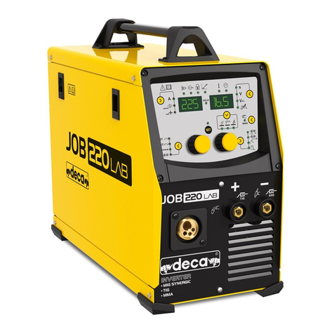
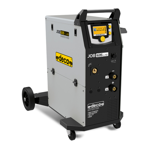
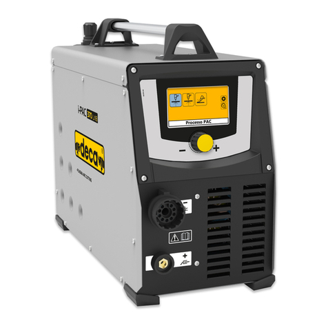
Deca JOB 220 LAB User manual

1
950005-00 01/03/21
IT 6 Manuale istruzione
EN 12 Instruction Manual
FR 17 Manuel d’instruction
ES 23 Manual de instrucciones

1
950005-00 01/03/21
Fig.1
Fig.2
Kg
C
A
B
F
G
H
I
O
P
Q
*
L
M
XXXXXXXXXXX
UV
1=XXX
1~XX/XXHz
XXA/XXXV-XXXA/XXV
XA/XXV-XXXA/XXV
X 40 % 60 %
UV
o= XX
100 %
I
2
XXX A XXX A XXX A
U
2
XXX V XXX V XXX V
X60 %
UV
o= XX
100 %
I
2
XX A XX A
XX V XX V
U
2
40 %
XX A
XX V
IA
1eff
XX
EN XXXXX/X
XXXXXXXXXXXXXX
Serial N.
IP XX
S
X~X~ f1
f2
S
IA
1max
XX
A
BB
C
E
KK
H
G
II
JJ
D2
D3
F
XXA/XXXV-XXXA/XXV
X60 %
UV
o= XX
100 %
I
2
XX A XX A
XX V XX V
U
2
40 %
XX A
XX V
S
D1
0
10
20
30
40
50
60
70
020406080100 120 140 160 180 200
AMP
Static Characteristic
MIGProcess
MMA Process
MIG Load Line
MMA Load Line
TIG Load Line
VOLT
*
Kg 5Ø200
Fig.3
T.3 Pulse
T.2
T.1
Al Si
Al Mg
Fe
Cu Si
Fe
Cu Si
Fe
Cu Si
27mm
E
D

2
950005-00 01/03/21
Fig.10
GASGAS
6-8Lt/min
Fig.4
Fig.7
Steel-Fe0,6-0,8
0,8-1,0
Aluminium -Al
Ø mm.
Ref.
011220
Steel-Fe1,0-1,2 011221
011222
1,0-1,2
Aluminium -Al011223
Flux 0,9-1,0/1,2 011224
Fig.8
Fig.9
max(A)
2
240V
230V
220V
mm
2
Ø mm.
9,1 9,2 9,3
240V
230V
220V
SPEED
m/min
m/min
1,0-20
I max (A) X (%)
CO2
Mix
Voltage class=113 Volt
0,6-1,2
60
60
180 DC
150 DC
Cooling
Air
Max
110cm
Zmax **
ohm
9,4
Ø37 mm
Fig.11
da
db
1~
200 25A “C” 32A 16 0,254
I
** Zmax 1Ph 230 V
4
5
67 8
1 2
3
4mm
m/min
1,0-20
CO2
Mix 0,6-1,2
60
60
230 DC
220 DC Air

3
950005-00 01/03/21
1
1
2
2
3
3
Fe Wire
adapter
4
4
Fe (metal liner)
8
8
O ring
PUSH
PUSH
5
5
6
6
7
7
Al (teflon liner)
Teflon
Metal
Liner
45mm
45mm
9
9
10
10
Fe Wire
adapter
OK!
OK!
Al-Cu/SI3: teflon liner Set-up

4
950005-00 01/03/21
Produttore Manufacturer
Producteur Fabricante
Hersteller
DECA s.p.a.
Strada dei Censiti, 10
Z.I.Rovereta 47891 Falciano
Repubblica di San Marino
Eco Design Information
Processo di saldatura Welding process Procédé de soudage Proceso
de soldadura Schweißprozess
MIG MAG - MMA - TIG
Nome del prodotto Product name Nom du produit Nombre del producto
Produktname
JOB 220 LAB 1Ph 230V 50/60Hz
Modelli equivalenti Equivalent model Modèle équivalent Modelo
equivalente Ersatzmodell
JOB 522 LAB 1Ph 230V 50/60Hz
JOB 522P LAB 1Ph 230V 50/60Hz
JOB 523 LAB 1Ph 230V 50/60Hz
JOB 523P LAB 1Ph 230V 50/60Hz
JOB 524 T3 LAB 1Ph 230V 50/60Hz
•
Efficienza con consumo energetico al massimo / Assorbimento a vuoto
•
Efficiency when max power consumption / Idle power consumtion
•
Efficacité à la consommation d'énergie maximale / Absorption à vide
•
Eficiencia con máximo consumo energético / Consumo de energía inactivo
•
Effizienz bei maximalem Energieverbrauch / Energieverbrauch im Leerlauf
> 80,0 % / < 25 W
•
Il valore dell’efficienza e del consumo in stato di inattività è stato misurato come indicato nella norma di prodotto EN 60974-1: 20XX.
•
The value of efficiency and consumption in idle state have been measured as per product standard EN 60974-1:20XX.
•
La valeur du rendement et de la consommation à l’état de repos ont été mesurées comme indiqué dans la norme produit EN 60974-1: 20XX.
•
El valor de la eficiencia y el consumo en estado inactivo se han medido como es indicado en la norma de producto EN 60974-1: 20XX.
•
Der Wert für Effizienz und Verbrauch im Leerlauf wurde gemäß der Produktnorm EN 60974-1: 20XX gemessen.
MIG MAG
Utilizzo tipico gas Typical gas usage Utilisation typique de gaz Uso típico gas Typischer Gasverbrauch
Materiale
Material
Matériel
Material
Material
Filo
Wire
Fil
Hilo
Draht
(mm)
Elettrodo DC
DC electrode
Électrode DC
Electrodo DC
Gleichstromelektrode
(Ampere / Voltage)
Consumo filo
Wire feeding
Alimentation fil
Alim. de alambre
Drahtvorschub
(m/min)
Gas di protezione
Shielding gas
Gaz du protection
Gas protector
Schutzgas
Flusso di gas
Gas flow
Flux du gaz
Flujo de gas
Gasstrom
(l/min)
Acciaio, steel,acier
acero, sthal
0,9 - 1,1
95 –200 / 18-22
3,5 –6,5
Ar 75%, CO2 25%
12
Alluminio
Aluminium,
0,8 - 1,6
90 –240 / 12 –26
5,5 –9,5
Argon
14 - 19
Inox Stainless
steel, inox,
rostfreier Stahl
0,8 –1,6
85 –300 / 21 –28
3 –7
Ar 98%, O2 2%
He 90%, Ar 7,5%, CO2 2,5%
14 - 16
Rame, copper,
cuivre, cobre,
Kupfer
0,9 –1,6
175 –385 / 23 –26
6 –11
Argon
12 - 16
Magnesium
1,6 –2,4
70 –335 / 16 - 26
4 - 15
Argon
24 - 28
TIG (WIG)
Utilizzo tipico gas Typical gas usage Utilisation typique de gaz Uso típico gas Typischer Gasverbrauch
•
L’utilizzo del gas dipende dall’area della sezione trasversale dell’ugello; per torce di uso comune:
•
Gas usage depends on cross-sectional area of the nozzle; for commonly used torches:
•
L’utilisation de gaz dépend de la section transversale de la buse; our les torches couramment utilisées:
•
El uso de gas depende del área de la sección transversal de la boquilla; para antorchas de uso común:
•
Der Gasverbrauch hängt von der Querschnittsfläche der Düse ab ;: für häufig verwendete Taschenlampen :
Elio - Helium - Hélium (He): = 14 - 24 l/min
Argon (Ar) = 7 - 16 l/min
•
Una portata eccessiva può provocare turbolenze nel flusso di gas che possono aspirare contaminazioni atmosferiche nel bagno di saldatura. Una
corrente d’aria può interrompere la copertura del gas di protezione: per risparmiare gas
utilizza uno schermo protettivo che blocchi l’aria.
•Excessive flow rates cause turbulence in the gas stream which may aspirate atmospheric contamination into the welding pool. A cross wind
can
disrupt the shielding gas coverage: in order to save the protective gas, use screen to block air flow.
•Des débits excessifs provoquent des turbulences dans le flux de gaz qui peuvent aspirer la contamination atmosphérique dans la piscine de soudage.
Un
vent transversal peut perturber la couverture du gaz de protection: afin d'économiser le gaz utilisez un écran pour bloquer le flux d'air.
•
Los caudales excesivos provocan turbulencias en la corriente de gas que pueden aspirar la contaminación atmosférica al baño de soldadura.
Un viento cruzado puede interrumpir la cobertura del gas protector : para ahorrar el gas protector, use pantalla para bloquear el flujo de aire.
•
Übermäßige Durchflussraten verursachen Turbulenzen im Gasstrom, die atmosphärische Verunreinigungen in das Schweißbad ansaugen
können. Ein Seitenwind kann die Schutzgasabdeckung stören.Um das Schutzgas zu sparen, verwenden Sie ein Sieb, um den Luftstrom zu
blockieren.
950021-00

5
950005-00 01/03/21
PERICOLO RADIAZIONI ULTRAVIOLETTE • DANGER OF ULTRA VIOLET RADIATION • RISQUE: RADIATIONS ULTRAVIOLETTES • PELIGRO RADIACIONES ULTRAVIOLETAS • PERIGO DE
PERICOLO SCHIACCIAMENTO MANO DA INGRANAGGI • DANGER OF CRUSHING HANDS IN GEARS • RISQUE: ÉCRASEMENT DE LA MAIN PAR LES ENGRENAGES • PELIGRO DE
PERICOLO RADIAZIONI NON IONIZZANTI • DANGER OF NON-IONIZING RADIATION • RISQUE: RADIATIONS NON IONISANTES • PELIGRO RADIACIONES NO IONIZANTES • PERIGO DE
PERICOLO CAMPO MAGNETICO INTENSO • DANGER OF STRONG MAGNETIC FIELD • RISQUE: CHAMP MAGNÉTIQUE INTENSE • PELIGRO CAMPO MAGNÉTICO INTENSO • PERIGO DE
VIETATO L’ACCESSO AI PORTATORI DI PACEMAKER • ENTRY NOT PERMITTED TO PERSONS FITTED WITH PACEMAKER • INTERDICTON: L’ACCÈS EST INTERDIT AUX PORTEURS DE
(IT)(EN)(FR)(ES) SEÑALES
(PT)(EL)(DE) GEFAHR, PFLICHTEN
(DA)(NL)(SV)
(FI)(ET)(LV) RISKA
(LT)(PL)
(CS) (SK)
(HU)(RU) (BG)
(HR)(NO)(SL)
IN PREPOVEDI (RO)(TR))يبرع)

6
950005-00 01/03/21
(IT) Smaltimento apparecchiature elettriche ed elettroniche: Simbolo che indica la raccolta separata delle apparecchiature elettriche ed elettroniche . L’utilizzatore
(EN)
Electrical and electronic equipment disposal: Symbol indicating separate collection for waste of electrical and electronic equipment. When the end-user wishes
to discard this product, it must not be disposed of as (unsorted) mixed municipal solid waste but sent to duly authorised collection facilities. (FR) Elimination
des appareillages électriques et électroniques: Symbole qui indique la collecte séparée des appareillages électriques et électroniques. L’utilisateur a l’obligation
de ne pas éliminer cet appareillage comme un déchet solide urbain mixte, mais doit s’adresser à des centres de récolte autorisés. (ES) Eliminación de
equipos eléctricos y electrónicos: Símbolo que indica la recogida diferenciada de los equipos eléctricos y electrónicos. El usuario tiene la obligación de no
eliminar este equipo como residuo sólido urbano mixto (indiferenciado), sino que debe dirigirse a los centros de recogida autorizados. (PT) Eliminação de
aparelhagens eléctricas e electrónicas. Símbolo que indica a recolha separada das aparelhagens eléctricas e electrónicas. O utilizador possui a obrigação
de não eliminar esta aparelhagem como resíduo sólido urbano misto (indiferenciado) e sim dirigir-se aos centros de recolha autorizados. (DE) Entsorgung
elektrischer und elektronischer Geräte: Symbol, das die getrennte Entsorgung von elektrischen und elektronischen Geräten angibt. Der Anwender hat die
(DA)
(NL) Afval van elektrische
en elektronische apparatuur. Dit symbool staat voor afval van elektrische en elektronische apparatuur dat gescheiden moet worden van ander afval. De
gebruiker mag dit afval niet bij het gewone stedelijke afval doen, maar moet het naar een speciaal en erkend verzamelpunt brengen. (SV) Avfallshantering för
elektrisk och elektronisk utrustning Symbol som indikerar separat avfallshantering för elektrisk och elektronisk utrustning. Användaren får inte slänga denna
utrustning såsom fast avfall (ej sorterad) men måste vända sig till en auktoriserad uppsamlingsplats för sorterad avfallshantering. (NO) Avhending av elektriske
vanlig restavfall, og må i stedet henvende seg til godkjente oppsamlingsstasjoner. (FI) Sähkö- ja elektroniikkalaitteiden hävittäminen. Symboli, joka osoittaa
sähkö- ja elektroniikkalaitteiden erilliskeräyksen. Käyttäjä ei saa hävittää tätä laitetta normaalin kiinteän kaupunkijätteen (lajittelematon) mukana vaan hänen
tulee toimittaa se valtuutettuun keräyspisteeseen. (ET) Elektriliste aparaatide ja elektroonikaseadmete jäätmekäitlus. Sümbol tähistab elektriliste aparaatide ja
elektroonikaseadmete eraldi kogumise kohustust. Kasutaja on kohustatud pöörduma volitatud kogumiskeskuste poole ning seda aparaati ei tohi käsitleda kui
segajäädet.. (LV)
(LT)
(PL)
(CS)
(HU) Az elektromos és elektronikus készülékek ártalmatlanítása. Az elektromos és elektronikus készülékek
(SK)
(HR)
(SL) Odstranjevanje
odpadke. (EL)
(RU)
(BG)
(RO)
a se adresa centrelor de colectare autorizate. (TR)
•
IT
Manuale istruzione
Prima di utilizzare la macchina leggere attentamente il
manuale istruzioni.
Gli impianti per saldatura ad arco MMA, TIG, MIG/MAG; gli
impianti per taglio al plasma in seguito chiamati “macchina”
sono previsti per uso industriale e professionale.
Assicurati che la macchina sia installata e riparata da persone
esperte in conformità alle leggi ed alle norme antinfortunistiche.
Assicurati che l’operatore sia addestrato sull’utilizzo e sui
rischi connessi al procedimento di saldatura ad arco / taglio
ad arco e sulle necessarie misure di protezione e procedure
di emergenza.
Puoi trovare informazioni dettagliate nel fascicolo
“Apparecchiature per saldatura ad arco installazione ed uso”:
IEC o CLC/TS 62081.
Avvertenze di sicurezza
Assicurati che la presa d’alimentazione a cui colleghi la
macchina sia protetta dai dispositivi di sicurezza (fusibili od
interruttore automatico) e che sia collegata all’impianto di terra.
Assicurati che la spina ed il cavo d’alimentazione siano in
buone condizioni.
Prima d’inserire la spina nella presa d’alimentazione, assicurati
che la macchina sia spenta.
Spegni la macchina ed estrai la spina dalla presa
d’alimentazione appena hai terminato il lavoro.
Spegni la macchina ed estrai la spina dalla presa
d’alimentazione prima di collegare i cavi di saldatura, installare
(usa la maniglia presente sulla saldatrice).
Non toccare le parti sotto tensione elettrica con la pelle
nuda o con indumenti bagnati. Isola elettricamente te
stesso dall’elettrodo, dal pezzo da tagliare e da eventuali
parti metalliche accessibili, collegate a terra. Utilizza guanti,
calzature, indumenti previsti allo scopo e tappeti isolanti

7
950005-00 01/03/21
Quando è possibile, intreccia fra loro i cavi di saldatura,
Non avvolgere i cavi di saldatura attorno al corpo.
Collega il cavo di massa al pezzo da lavorare il più vicino
possibile al punto da saldare.
Non saldare tenendo la saldatrice appesa al corpo.
Tieni il capo ed il tronco il più lontano possibile dal circuito
di saldatura. Non lavorare vicino, seduto o appoggiato alla
saldatrice. Distanza minima: Fig 11 Da = cm 50; Db = cm.20
Apparecchiatura di Classe A
Questa apparecchiatura è progettata per l’uso in ambienti
industriali e professionali.
Negli ambienti domestici ed in quelli collegati ad una rete
di alimentazione pubblica a bassa tensione che alimentano
assicurare la rispondenza alla compatibilità elettromagnetica,
a causa di disturbi condotti o irradiati.
Saldatura (taglio) in condizioni a rischio
Se devi lavorare in condizioni di rischio accresciuto di scariche
od esplodenti assicurati che un responsabile esperto valuti
preventivamente le condizioni. Assicurati che siano presenti
delle persone addestrate per intervenire in casi di emergenza.
Adotta i mezzi tecnici di protezione descritti in 5.10; A.7; A.9
Se devi lavorare in posizioni sollevate dal suolo utilizza sempre
piattaforme di sicurezza.
Se più macchine lavorano sullo stesso pezzo o comunque su
pezzi elettricamente collegati, le tensioni a vuoto presenti sui
porta-elettrodo o sulle torcia si possono sommare superando
il livello di sicurezza. Assicurati che un responsabile esperto
valuti preventivamente se esiste un rischio ed eventualmente
tecnica IEC o CLC/TS 62081.
Avvertenze supplementari
Non utilizzare la macchina per scopi non previsti come per
esempio scongelare tubazioni della rete idrica.
evita che possa muoversi. La posizione deve permetterne
il controllo, ma non deve consentire alle scintille di colpirla.
Non sollevare la macchina. Non sono previsti sistemi di
sollevamento.
Non utilizzare cavi con isolamento deteriorato o con le
connessioni allentate.
Messa in funzione
Gli allacciamenti elettrici devono essere eseguiti da persone
Assicurati che la macchina sia spenta e scollegata dalla presa
d’alimentazione durante tutti i passi della messa in funzione.
Assicurati che la presa d’alimentazione a cui colleghi la
macchina sia protetta dai dispositivi di sicurezza (fusibili od
interruttore automatico) e che sia collegata all’impianto di terra.
L’apparecchio deve essere collegato esclusivamente ad
un sistema di alimentazione con il conduttore del “neutro”
collegato a terra.
Consigli per l’uso
Utilizza una prolunga elettrica solo quando è necessario
e purché sia di sezione pari o superiore a quella del cavo
d’alimentazione e dotate del conduttore di terra.
Non bloccare le prese d’aria della macchina. Non racchiuderla
Utilizza la macchina in ambiente asciutto e ventilato. Non
esporre la macchina alla pioggia ed al sole battente.
Utilizza la macchina solo se tutti i pannelli e schermi sono al
loro posto e montati correttamente.
Non utilizzare la macchina se è caduta oppure è stata urtata
perché potrebbe non essere sicura. Falla controllare da una
Elimina i fumi di saldatura (taglio) con un’adeguata ventilazione
naturale o con un aspiratore di fumi. E’ necessario utilizzare
un approccio sistematico per valutare i limiti all’esposizione ai
fumi di saldatura (taglio) in funzione della loro composizione,
concentrazione e durata dell’esposizione stessa.
Non saldare (tagliare) materiali puliti con solventi clorurati o
comunque vicino a tali sostanze.
Usa la maschera di saldatura con un vetro inattinico adeguato
al processo di saldatura (taglio). Sostituiscila se è danneggiata;
le radiazioni possono attraversarla.
Indossa guanti, calzature ed indumenti ignifughi che
proteggano la pelle dai raggi prodotti dall’arco di taglio
e dalle scintille. Non usare indumenti unti o grassi, una
scintilla potrebbe incendiarli. Usa degli schermi protettivi per
proteggere le persone vicino a te.
Non toccare con la pelle nuda le parti metalliche incandescenti
quali: torcia, pinza porta elettrodo, mozziconi d’elettrodo, pezzi
appena lavorati.
La lavorazione del metallo provoca scintille e schegge.
Indossa occhiali di sicurezza, con protezione ai lati degli occhi.
Le scintille della saldatura (taglio) possono causare incendi.
Non saldare (tagliare) in aree dove sono presenti materiali,
Non saldare (tagliare) contenitori, bombole, serbatoi o
non abbia verificato che si possano lavorare e li abbia
opportunamente preparati.
Togli l’elettrodo dalla pinza porta elettrodo quando hai
terminato la saldatura. Assicurati che nessuna parte del
circuito elettrico della pinza porta elettrodo tocchi il circuito
di massa o di terra: un contatto accidentale può causare
surriscaldamenti e principi d’incendio.
EMF Campi elettromagnetici
La corrente di saldatura genera campi elettromagnetici (EMF),
in prossimità del circuito di saldatura e della saldatrice. I campi
elettromagnetici possono interferire con protesi mediche, quali
per esempio pacemaker.
Vanno prese adeguate misure protettive nei confronti dei
portatori di protesi mediche. Per esempio, deve essere
impedito l’accesso all’area di utilizzo della saldatrice. I portatori
di protesi mediche, devono consultare il medico prima di
avvicinarsi all’area di utilizzo della saldatrice.
Questa apparecchiatura soddisfa i requisiti dello standard
tecnico di prodotto per l’uso esclusivo in ambiente industriale
ed uso professionale. Non è assicurata la rispondenza ai limiti
previsti per l’esposizione umana ai campi elettromagnetici in
ambiente domestico.
Applica i seguenti accorgimenti per minimizzare l’esposizione
ai campi elettromagnetici (EMF):
Non posizionarti col corpo fra i cavi di saldatura. Tieni entrambi
i cavi di saldatura dallo stesso lato del corpo.

8
950005-00 01/03/21
Non utilizzare la macchina in ambienti contenenti: gas, vapori,
polveri conduttive (es. limatura di ferro), aria salmastra, fumi
caustici ed altri agenti che possano danneggiare le parti
metalliche e gli isolamenti elettrici.
LLe parti elettriche della macchina sono state trattate con
resine protettive. Al primo utilizzo potresti notare del fumo;
si tratta della resina che si essicca completamente. La
fuoriuscita di fumo durerà solo per alcuni minuti.
Descrizione della saldatrice
continuo, comunemente denominata MIG / MAG, adeguato
alla saldatura, con l’ausilio di un gas protettivo, di acciai al
carbonio o debolmente legati; degli acciai inossidabili e
dell’alluminio.
La saldatrice è un trasformatore di corrente per la saldatura
manuale ad arco di elettrodi rivestiti MMA e TIG con una torcia
ad innesco dell’arco a contatto.
La saldatrice è realizzata con la tecnologia elettronica
INVERTER.
Organi principali Fig.1
A)Pannello d’accesso al vano bobina
D)Cavo d’alimentazione
E)Ingresso del gas di protezione
F) Interruttore ON/OFF acceso o spento
G) Connettore torce speciali
H)Attacco torcia MIG
I) Attacchi per cavi di saldatura
O) Connettore per Sd Card
P)Pulsante Test gas
Dati tecnici
La targa dati è presente sulla saldatrice. La Fig.2 è un esempio
della targa stessa.
A)Nome ed indirizzo del costruttore
sicurezza degli impianti per saldatura
C)Simbolo della struttura interna della saldatrice
D)Simbolo del procedimento di saldatura previsto: D1: MIG;
D2: TIG; D3 MMA.
E)Simbolo della corrente erogata continua
F) Tipo d’alimentazione necessaria:
1˜ tensione alternata monofase; frequenza
G) Grado di protezione da corpi solidi e liquidi
H) Simbolo indicante la possibilità di utilizzare la saldatrice in
ambienti a rischio di scariche elettriche
I) Prestazioni del circuito di saldatura
U0V Tensione minima e massima a vuoto (circuito di
saldatura aperto).
I2, U2 Corrente e corrispondente tensione normalizzata
che la saldatrice eroga
XServizio di saldatura. Indica quanto tempo la
saldatrice può lavorare e quanto tempo deve essere
di lavoro e 4 min. di sosta).
A / V Campo di regolazione della corrente e rispettiva
tensione d’arco.
Dati relativi alla linea d’alimentazione
U1 Tensione d’alimentazione (tolleranza ammesa: +/-
10%)
I1 e
I1 max Massima corrente assorbita
K)N° Matricola
L) Peso
M)Simboli di sicurezza: Leggi le Avvertenze di sicurezza
Fig.8
Messa in funzione
Assemblaggio ed allacciamento elettrico
¾Assembla le parti staccate contenute nell’imballo Fig.10.
¾
corrispondenti a quella della saldatrice e che sia dotata di
un interruttore automatico adeguato alla massima corrente
nominale erogata (I2max) Fig.9,1.
LQuesta apparecchiatura non rientra nei requisiti della norma
IEC/EN61000-3-12. Se viene collegata ad una rete di
alimentazione pubblica a bassa tensione, è responsabilità
connessa; (se necessario, consultare il gestore della rete di
distribuzione elettrica).
L
(Flicker) si consiglia il collegamento della saldatrice ai punti
di interfaccia della rete di alimentazione che presentano
un’impedenza minore di Zmax= Fig.9,4.
Preparazione del circuito di saldatura MIG
¾Collega il cavo di massa alla saldatrice ed al pezzo da lavorare,
il più vicino possibile al punto di lavoro.
¾Collega la torcia** alla presa della saldatrice.
LLe torce con regolazione velocità sull’impugnatura e “Spool
gun” hanno uno spinotto che deve essere collegato nella
presa Fig.1 G
Installazione del lo continuo
Per l’installazione segui le indicazioni della Fig.3.
Se le misure non corrispondono potresti avere problemi di
L
ma se invece è troppo pressato, si potrà deformare e non
scorrerà liberamente nella torcia.
Funzione caricamento lo
Premi il tasto “Q” interno al vano bobina e subito dopo il
premuto.
Installazione della bombola del gas di
protezione** e del riduttore di pressione**
Assicura la bombola del gas di protezione in posizione
verticale, lontano dall’area di saldatura. Utilizza il supporto
non sia danneggiata.
Per l’installazione segui le indicazioni della Fig.4.
Funzione test gas
Premi il tasto “P” interno al vano bobina. L’elettrovalvola
chiuderà automaticamente dopo 30 secondi.
Preparazione del circuito di saldatura MMA
¾Collega il cavo di massa** alla saldatrice ed al pezzo da
lavorare, il più vicino possibile al punto di lavoro.

9
950005-00 01/03/21
¾Collega il cavo con la pinza porta elettrodo** alla saldatrice e
monta sulla pinza l’elettrodo. Fai riferimento alle indicazioni
del fabbricante degli elettrodi in merito al collegamento ed alla
corrente di saldatura.
Preparazione del circuito di saldatura TIG
¾Collega il cavo di massa** alla saldatrice ed al pezzo da
lavorare, il più vicino possibile al punto di lavoro.
¾Collega il connettore di potenza della torcia TIG** all’attacco
negativo della saldatrice e monta l’elettrodo. La torcia deve
¾Collega il tubo gas della torcia TIG all’uscita di un riduttore
di pressione montato su di una bombola di gas di protezione
ARGON.
LLe sezioni consigliate (mm2) per il cavo di saldatura, in
base alla massima corrente nominale erogata (I2max), sono
indicate nella Fig.9,3.
** (Questo componente può non essere incluso su alcuni
modelli).
Procedimento di saldatura: descrizione comandi
e segnalazioni
1 Manopola di regolazione principale.
2 Manopola per la regolazione della corrente di saldatura /
multifunzione.
3 Manopola per la regolazione della tensione di saldatura /
navigazione.
4 Display.
O Connettore SD_Card.
P Pulsante test gas.
Q
Vista: HOME
Vista: Saldatura MIG sinergica
Vista: Saldatura MIG Manuale
Vista: Selezione parametri di saldatura MIG
Vista: Saldatura MMA
Vista: Saldatura TIG
A Barra di stato. Indica le principali regolazioni in funzione.
B Valori misurati di corrente e tensione di saldatura.
C Valori impostati di spessore materiale / corrente di
visualizzare è fatta attraverso la pressione della manopola
“2”.
D Correzione della tensione di saldatura: maggiore o
minore penetrazione dell’arco. (manopola “3”).
EVelocità del lo in modalità manuale.
G Tensione di saldatura in modalità manuale.
H Barra dei parametri di saldatura. (Premi la manopola
“1”).
I Barra di navigazione. (Premi la manopola “3”).
M Corrente di saldatura In MMA e TIG. (manopola “2”).
N Numero del programma sinergico richiamato.
A
B
E
G
A
H
I
BM
A
1
2
3
4
O
P
Q
B
M
A
A
B
C
D
308
N

10
950005-00 01/03/21
Navigazione nelle viste
La manopola “1” ti consente di selezionare i parametri presenti
nella “Barra dei parametri di saldatura” e di impostare i
valori desiderati. Premi la manopola per confermare la scelta.
La manopola “3” comanda la “Barra di navigazione” per
muoversi fra le varie viste ed include anche alcune regolazioni
secondarie. Premi la manopola per confermare la scelta.
Impostazione processo di saldatura
Una volta che hai eseguito tutti i passi della messa in funzione,
accendi la saldatrice ed apri la valvola del gas di protezione.
La saldatrice è pronta per l’utilizzo con l’ultimo processo /
programma di saldatura utilizzato.
Selezione del processo di saldatura
¾Premi la manopola “3” e seleziona l’icona
¾Nella vista “HOME”, seleziona il processo di saldatura
desiderato. La saldatrice è pronta per l’utilizzo con l’ultimo
programma impostato.
Impostazione per la saldatura MIG sinergica
¾Premi la manopola “1”
saldatura” seleziona l’icona
¾Nella vista “Parametri di saldatura MIG” imposta il tipo di
(manopola “1”).
¾Nella vista di lavoro “Saldatura MIG sinergica” regola a tua
scelta: lo spessore del materiale, la corrente di saldatura o la
“2”).
¾La penetrazione dell’arco è regolata dalla manopola “3”.
LNel funzionamento sinergico tutti i parametri di saldatura
sono collegati fra di loro per facilitare la regolazione della
macchina.
Impostazione per saldatura MIG manuale
LAnche nella saldatura MIG manuale sono richiesti il
La selezione di questi parametri ti aiuterà nella regolazione
¾Premi la manopola “1” e nella barra dei parametri di saldatura
seleziona l’icona
¾Nella vista “Parametri di saldatura MIG” imposta il tipo di
(manopola “1”).
¾Nella vista di lavoro “Saldatura MIG manuale” regola la
“2”) e la
tensione di saldatura (Manopola “3”).
Impostazione saldatura MMA / TIG
¾
“HOME”.
¾La manopola “2” regola gli ampere di saldatura.
¾La manopola “3”
Barra dei parametri di saldatura
Nella “Barra dei parametri di saldatura” sono presenti alcune
regolazioni utili nei diversi processi di saldatura.
Torcia: 2 tempi; 4 tempi; “Spot”; “Stitch”
2 Tempi: la macchina inizia a saldare quando
premi il pulsante e si interrompe quando lo si
rilasci.
4 tempi: premi e rilascia il pulsante per iniziare
a saldare. Per interrompere premi e rilascia di
nuovo il pulsante.
Spot: quando premi il pulsante la macchina sal-
Stitch: quando premi il pulsante la macchina
inizia una serie di saldature e di interruzioni en-
Saldatura in modalità Spot. Occorre regolare il
tempo di saldatura.
Saldatura in modalità Stitch. Occorre regolare
il tempo di saldatura e di pausa.
Regolazione dell’induttanza.
Il valore dell’induttanza permette di ottimizzare gli
spruzzi di saldatura. Solitamente un alto valore
dell’induttanza aumenta la quantità di spruzzi indesi-
derati.
Regolazione velocità di accostamento del lo
da saldare all’inizio della saldatura.
Regolazione Burn Back MIG
Regolazione usso gas MIG
Regolazione Pre gas
Regolazione Post gas
Regolazione Hot Start MIG.
Regolazione della corrente di partenza.
Saldatura “Pulse, Pulse x 2”.
E’ possibile selezionare la saldatura pulsata oppure
la saldatura a doppia pulsazione.
Selezione torcia 1, 2, 3.
La selezione della torcia e del relativo programma di
saldatura avviene attraverso la pressionde del pul-
sante torcia oppure attraverso questo punto di menu.
Memorizza un programma utente.
Puoi salvare 128 regolazioni che hai impostato per
rizzato in precedenza vai nella vista HOME.
. Arc force / Hot start MMA.
Seleziona l’icona desiderata ed imposta il
valore voluto.
Slope Down (TIG)
Seleziona l’icona desiderata ed imposta il valore
voluto.

11
950005-00 01/03/21
Barra di navigazione
Ritorno alla vista HOME
Indietro alla vista precedente
Regolazioni secondarie
Selezione torcia spool gun
La torcia Spool Gun può essere collegata ad
ogni attacco centralizzato della saldatrice.
Calibrazione della velocità del lo
La regolazione della pressione dei rullini traina-
Per ottenere le migliori prestazioni dalla
1) All’inizio della calibrazione compare il
messaggio “Point 1” ed una misura: Es. “30”.
macchina farà uscire una certa lunghezza di
misura la lunghezza del lo.
4) Correggi la misura indicata nel display e premi
la manopola “1” per conferma.
Compare il messaggio Point 2 ed una
seconda misura Es. 90.
5) Ripeti la procedura dal passo (2).
Al termine della calibrazione la macchina ritorna
nella vista precedente
LDurante la calibrazione il gas e la potenza sono
spenti.
Funzione caricamento lo
Comando alternativo al tasto “Q” interno al vano
bobina.
Funzione test gas
Comando alternativo al tasto “P” interno al vano
bobina.
Informazioni varie di sistema
Funzioni secondarie nella vista HOME
Regolazioni generali
Selezione lingua.
Scelta interfaccia utente.
Puoi scegliere se visualizzare tutte le regolazioni
presenti “Barra dei parametri di saldatura” op-
pure solo quelle più necessarie in modo maniera
di rendere molto semplice la regolazione della
saldatrice.
Reset dei programmi utente
Cancella tutti i programmi utente.
Reset della macchina
riporta la macchina ai valori di fabbrica.
Versione software
Richiamo dei programmi di saldatura impo-
stati dalla fabbrica
Richiamo dei programmi di saldatura salvati
dall’utente
Informazioni varie di sistema
Connettore per sd card
Il connettore è utile per aggiornare il software della macchina
e caricare nuovi programmi sinergici.
¾A macchina spenta inserisci la sd card.
¾Accendi la macchina.
Il software viene caricato. Al termine dell’aggiornamento il
pannello comandi torna allo stato normale.
¾Rimuovi la sd card.
Messaggi di errore
Segnala che la macchina si trova ad operare in un
punto intermedio fra la saldatura “short arc” e la
saldatura “spray arc” (zona globulare). La coppia di
valori scelti per la saldatura (Amp, Volt) possono ge-
nerare archi instabili e spruzzi. Il messaggio compa-
re nella barra di stato.
Protezione termica attiva. Se superi il servizio di sal-
datura “X” riportato nella targa tecnica un protettore
termico interrompe il lavoro prima che la saldatrice
sia danneggiata.
macchina si ferma per 10 secondi. E’ opportuno
postato. Hai impostato una sinergia con un diametro
macchina
E50: Errore in fase di aggiornamento scheda display
E52: Errore in fase di aggiornamento scheda potenza
gramma corretto.
E51:
E53:
za.
Il software potrebbe essere corrotto. Prova a ricarica-
re il programma con la sd card.
E70: Guasto nella scheda di potenza.
E71: Guasto nel collegamento tra display e scheda di
potenza
E72: Guasto alla scheda display
E73: Guasto alla scheda di espansione
La macchina ha un componente elettronico in avaria,
è necessario l’intervento di un centro assistenza spe-
cializzato.
Manutenzione
Spegnilasaldatriceedestrailaspinadallapresad’alimentazione

12
950005-00 01/03/21
periodicamente in funzione dell’uso.
• Controlla i collegamenti del tubo gas, del cavo torcia e
del cavo massa. • Pulisci con una spazzola di ferro l’ugello
Pulisci la saldatrice all’esterno con un panno umido.
• Controlla l’allineamento, la pulizia e lo stato di usura del rullino
Fig.7 • Asporta la polvere metallica che si deposita
solventi anidri e sgrassanti ed asciuga con aria compressa. •
Controlla l’usura delle Etichette di avvertenza. • Sostituisci le
parti usurate.
Manutenzione straordinaria
periodicamente, in
funzione dell’uso.
• Ispeziona l’interno della saldatrice e rimuovi la polvere
depositata sulle parti elettriche (usa aria compressa) e sulle
schede elettroniche (usa una spazzola molto morbida o dei
prodotti appropriati).
i cablaggi non abbiano l’isolante danneggiato.
Ulteriori simboli utilizzati
Saldatura MIG manuale
Saldatura MIG sinergica
Saldatura MMA
Saldatura TIG
Tipo di materiale selezionato (icona rappresentativa)
Tipo di gas selezionato (icona rappresentativa)
Tipo di selezionato (icona rappresentativa)
Simbolo torcia in funzione
EN
Instruction Manual
Read this instruction manual carefully before using the welding
machine.
The MMA, TIG, MIG/MAG arc welding systems, Plasma cutting
systems referred to herein as “machine” are for industrial and
professional use.
Make sure that the machine is installed and repaired only by
in compliance with the law and
with the accident prevention regulations.
Make sure that the operator is trained in the use and risks
connected to the arc-welding process / plasma cutting process
and in the necessary measures of protection and emergency
procedures.
Detailed information can be found in the “Installation and use
of arc-welding equipment” brochure: IEC or CLC/TS 62081.
Safety warnings
Make sure that the power socket to which the machine
machine is connected is protected by suitable safety devices
(fuses or automatic switch) and that it is grounded.
Make sure that the plug and power cable are in good condition.
socket before connecting the welding cables, installing the
continuous wire, replacing any parts in the torch or wire feeder,
carrying out maintenance operations, or moving it (use the
carrying handle on the machine).
Insulate yourself from the electrode, the piece to be cut and
any grounded accessible metal parts. Use gloves, footwear
insulating mats.
Use the machine in a dry, ventilated space. Do not expose
the welding machine to rain or direct sunshine.
Use the machine only if all panels and guards are in place
and mounted correctly.
Do not use the machine if it has been dropped or struck, as
an expert.
Eliminate any welding (cutting) fumes through appropriate
natural ventilation or using a smoke exhauster. A systematic
approach must be used to assess the limits of exposure to
welding (cutting) fumes, depending on their composition,
concentration and the length of exposure.
Do not weld (cut) materials that have been cleaned with
chloride solvents or that have been near such substances.
Use a welding mask with inactinic glass suitable for welding
(cutting) operations. Replace the mask if damaged; it may let
in radiation.
from the rays produced by the welding arc and from sparks. Do
Use protective screens to protect people nearby.
Do not allow bare skin to come into contact with hot metal
parts, such as the torch, electrode holder grippers, electrode
stubs, or freshly cut pieces.
goggles with protective side eye guards.
gasses or vapours.
Do not weld or cut containers, cylinders, tanks or piping unless
to do so, or has made the appropriate preparations.
Remove the electrode from the electrode holder gripper when
you have completed the welding operations. Make sure that
no part of the electrode holder gripper electric circuit touches
the ground or earth circuits: accidental contact could cause
EMF Electromagnetic Fields

13
950005-00 01/03/21
interfere with medical prostheses such as pacemakers.
to protect those operators having such aids. For instance,
they should not be allowed to enter that area where welding
equipment is used. Any operator having such aids should
consult their doctor before coming close to an area where
welding equipment is used.
technical standard and is intended for professional use in an
industrial environment only. Compliance to expected limits
ensured.
Followthesestrategiestominimiseexposuretoelectromagnetic
welding cables should be on the same side of your body.
Twist both welding cables together and secure them with tape
when possible.
Do not wrap the welding cables around your body.
Connect the earth cable to the workpiece as close as possible
to the area to be welded.
Do not work with the welder hanging from your body.
Keep your head and trunk as far as possible from the welding
circuit. Do not work close to the welder, or seated or leaning
on it. Minimum distance: Fig 11 Da = cm 50; Db = cm.20
Class A equipment
This equipment has been designed to be used in professional
and industrial environments.
If this equipment is used in domestic environments and those
directly connected to a low voltage power supply network
which supplies buildings used for domestic purposes, it may be
as the result of conducted or radiated disturbances.
Welding (cutting) in conditions of risk
IIf you are required to work in conditions of risk (electric
discharges, suffocation, the presence of inflammable or
explosive materials), make sure that an authorised expert
evaluates the conditions beforehand. Make sure that trained
people are present who can intervene in the event of an
emergency. Use the protective equipment described in 5.10;
If you are required to work in a position raised above ground
level, always use a safety platform.
If more than one machine has to be used on the same piece,
or in any case on pieces connected electrically, the sum of the
no-load voltages on the electrode holders or on the torches
may exceed the safety levels. Make sure that an authorised
expert evaluates the conditions beforehand to see if such risk
exists and adopt the protective measures described in 5.9 of
Additional warnings
Do not use the machine for purposes other than those
described, for example to thaw frozen water pipes.
that it cannot move. It must be positioned in such a way as
to allow it to be controlled during use but without the risk of
being covered with sparks.
machine.
Do not use cables with damaged insulation or loose
connections.
Starting up
personnel.
from mains before carrying out this procedure.
Make sure that the power socket that the machine is plugged
into is protected by safety devices (fuses or automatic switch)
and grounded.
The device must be connected only to a supply system, with
an earthed ‘neutral’ lead.
Recommendations for use
Only use an extension lead when absolutely necessary and
providing it has an equal or larger section to the power cable
Do not block the machine air intakes. Do not store the machine
in containers or on shelving that does not guarantee suitable
ventilation.
Do not use the machine in any environment in the presence
of gas, vapours, conductive powders (e.g. iron shavings),
brackish air, caustic fumes or other agents that could damage
the metal parts and electrical insulation.
LThe electric parts of the machine have been treated with
protective resins.
be noticed; this is caused by the resin drying out completely.
The smoke should only last for a few minutes.
Description of the welding machine
The welding machine is a current generator for continuous wire
welding, commonly known as MIG / MAG, suited to welding
carbon or light alloy steels, stainless steel and aluminium
using protective gas.
(constant
voltage).
The welding machine is a current transformer for manual arc
welding using MMA coated electrodes and TIG with a torch
that strikes the arc on contact.
The delivered current is direct.
The electrical characteristic of the transformer is of the falling
type.
The welding machine is built using electronic INVERTER
technology.
Main parts Fig. 1
A)Spool compartment access door
C)Wire feeder
D)Power cable
E)Gas hose connection
F) ON/OFF switch
G) Special torch connector
H)Torch connector
I) Couplings for welding cables.
O) Sd card connector
P)Gas test function
Q) Wire load function
Technical data
Fig. 2 shows an
example of this plate.
A)Constructor name and address
safety of welding equipment
C)Symbol of the welding machine internal structure
D)Symbol of the foreseen welding process: D1: MIG; D2:
TIG; D3 MMA.

14
950005-00 01/03/21
E)Symbol of the continuous current delivered
F) Input power required:
1˜ alternate single phase voltage, frequency
G) Level of protection from solids and liquids
H) Symbol indicating the possibility to use the welding
machine in environments potentially subject to electric
discharges
I) Welding circuit performance
U0V Minimum and maximum open circuit voltage (open
welding circuit).
I2, U2 Current and corresponding normalised voltage
delivered by the welding machine.
XDuty cycle. Indicate how long the welding machine
can work for and how long it must rest for in order to
cool down. The time is expressed in % on the basis
of a 10 minute cycle (e.g. 60% means 6 min. work
and 4 min. rest).
A / V
voltage.
U1 Input voltage (permitted tolerance: +/- 10%)
I1 e
I1 max Maximum absorbed current
K)Serial number
L) Weight
M)Safety symbols: Refer to Safety Warnings
Technical data for torch and wire feeder Fig.8
Starting up
Assembly and electrical connections
¾Assembly the detached parts found in the packaging Fig.10.
¾Check that the electrical supply delivers the voltage and
frequency corresponding to the welding machine and that
delivered rated current (I2max) Fig. 9,1.
LThe requirements set out in the IEC/EN61000-3-12 standard
do not apply to this equipment. If this equipment is connected
to low voltage power supply network, either the installer or
the user is responsible for checking that this can be done
(consult the distribution system operator if required).
LIn order to comply with the requirements set out in the
EN61000-3-11 (Flicker) standard, it is advisable to connect
the welder to the supply network interface points having an
impedance lower than the reference Zmax = Fig.9,4.
Preparing the welding circuit MIG
¾Connect the ground lead to the welding machine and to the
piece to be welded, as close as possible to the point to be
welded.
¾Connect the torch** to the welding machine socket.
LThe torches with speed controls on the handle and Spool
guns have a pin that must be connected in the socket G
Fig. 1.
Installing the continuous wire
For installation, follow the instructions in Fig. 3.
The material and diameter of the wire must correspond to
the wire feeder roller, the contact tip and the torch liner. If the
measurements do not match, there may be problems with the
smooth running of the wire.
LThe pressure of the wire pressing knob is important for correct
operation. If the wire slips, there will be problems with the
welding; if on the other hand it is too tight, it may be deformed
and will not run smoothly through the torch.
Wire load function
Press the button “Q” inside the coil compartment and then the
button on the torch. The wire is loaded even after releasing the
button “Q” until the button on the torch is pressed.
Installing the protective gas cylinder** and pressure
reducer**
Place the protective gas cylinder in an upright position, far
away from the welding area. Use the welding machine support
being damaged.
For installation, follow the instructions in Fig. 4.
Gas test function
Press the button “P” inside the coil compartment. The
solenoid valve remains open until the button is pressed again,
or it will close automatically after 30 seconds.
Preparing the welding circuit MMA
¾Connect the ground lead** to the welding machine and to
the piece to be welded, as close as possible to the point to
be welded.
¾Connect the cable with the electrode holder gripper** to the
welding machine and mount the electrode on the gripper.
Refer to the electrode manufacturer’s instructions concerning
connection and welding current.
Preparing the welding circuit TIG
¾Connect the ground lead** to the welding machine and to
the piece to be welded, as close as possible to the point to
be welded.
¾Connect the TIG torch** power connector to the negative
attachment on the welding machine and mount the electrode.
¾Connect the TIG torch gas pipe to the output of the pressure
reducer mounted on an ARGON protection gas cylinder.
LThe recommended sections (mm2) of the welding cable,
based on the maximum delivered rated current (I2 max),
are shown in Fig. 9,3.
** (This component may not be included with some
models).
Welding process: description of controls
1 Main adjustment knob
2Welding current adjustment / multifunction knob
3Welding voltage adjustment / navigation knob
4 Display
O Sd card connector
P Gas test function
Q Wire load function
1
2
3
4
O
P
Q

15
950005-00 01/03/21
Screenshot: HOME
Screenshot: Synergic MIG welding
Screenshot: manual MIG welding
Screenshot: MIG welding parameters
Screenshot: MMA welding
Screenshot: TIG welding
A Statusbar. Indicates the main adjustments in operation.
B Measured values of welding current and voltage.
C Set values of material thickness / welding current / wire
speed. The choice of which value to display is made by
pressing the “2” knob.
D Correction of welding voltage: greater or lesser
penetration of the arc. (Knob “3”).
E Wire speed on manual welding.
G Welding voltage on manual welding.
H Welding parameters bar. (Press knob “1”).
I Navigation bar. (Press knob “3”).
M Welding current on MMA / TIG process. (Knob “2”).
N Synergic programs reference number
Browse through Views
Knob “1” allows you to select the parameters present in the
“Welding parameters bar” and to set the desired values.
Knob “3” controls the “Navigation bar”.It is used to move
between the various views and also includes some secondary
Welding process setup
After commissioning, switch on the welding machine, open the
protection gas valve.
The welding machine is ready for use with the last welding
process / program used.
Select the welding process
¾Press knob “3” and select the icon:
¾In the “HOME” view, select the desired welding process. The
welding machine is ready with the last program used.
Setting for synergic MIG welding
¾Press knob “1” and in the welding parameters bar select the
icon:
¾In the “MIG welding parameters” view, set the type of
material, the wire diameter and the type of shielding gas.
(knob “1”).
¾In the “Synergic MIG welding” work view set, as per your
custom, the thickness of the material, or the welding current
or the wire speed (Knob “2”).
¾The arc penetration is adjusted by knob “3”.
LIn synergistic mode, all welding parameters are connected
to each other to facilitate the setting of the machine.
Setting for manual MIG welding
LAlso in manual MIG welding it is necessary to set the material,
the wire thickness and the type of shielding gas. The selection
of these parameters will help you to adjust the wire speed
and the welding voltage.
¾Press knob “1” and in the “welding parameters bar” select
the icon:
¾In the “MIG welding parameters” view, set the type of
material, the wire diameter and the type of shielding gas.
(knob “1”).
¾In the “Manual MIG welding” work view, set the wire speed
(Knob “2”) and welding voltage (Knob “3”).
A
B
E
G
A
H
I
B
M
A
B
M
A
A
B
C
D
308
N

16
950005-00 01/03/21
Setting for MMA / TIG welding
The selection of the welding process is carried out in the
“HOME” view.
¾Knob “2” adjusts the welding current.
¾Knob “3” controls the “Navigation bar”.
Welding parameter bar
In the “Welding parameters bar” there are some useful
Selecting 2 stages; 4 stages; “Spot”; “Stitch
2 Stages: the machine starts welding when the
button is pressed and stops when the button is
released.
4 Stages: press and release the button to start
welding. Press and release the button again to
stop welding.
Spot: when the button is pressed the machine
welds for a set period of time and then stops.
Stitch: when the button is pressed the machine
starts a series of welds and pauses for the set
duration.
Spot welding. The welding time needs to be
adjusted.
Stitch welding. The rest time needs to be adju-
sted .
Inductance value setting.
The inductance value allows you to optimize the weld
spatter. Usually a high inductance value increases
the amount of unwanted splashing.
Adjusting MIG wire approach speed.
part to be welded at the start of the welding cycle.
Adjusting Burn Back
wire that sticks out of the contact tip at the end of the
welding cycle.
Adjusting gas ow time MIG
Adjusting Pre gas time
Adjusting Post gas time
Adjusting Hot Start MIG.
Setting “Pulsed, Pulsed x 2” welding.
Pulsed welding or double pulsation welding can be
selected.
Setting torches 1, 2, 3.
The torch and the related welding program are
selected by pressing the torch trigger or through this
menu point.
Store user program.
To recall a stored program, go to the HOME view.
. Adjusting Arc force and Hot start (MMA).
Select the desired icon and set the proper
value.
Adjusting Slope Down (TIG)
Select the desired icon and set the proper value.
Navigation bar
Back to HOME view.
Back to the previous view.
Settings
Selecting spool gun torch.
The spool gun torch can be connected to any
centralized connection of the welding machine.
Calibrating the wire speed.
Adjusting the pressure of the wire feed rollers
feed speed.
For better performance, calibrate the wire feed.
1) At the start of the calibration process
the message “Point 1” appears with a
measurement: e.g. “30”.
2) Cut the welding wire outside the wire guide
tip and press the torch button. The machine
releases a certain length of wire.
3) Cut the welding wire outside the wire guide tip
and measure the wire length.
4) Correct the measure indicated on the display
and press the control “1
The message Point 2 appears with a second
measurement: e.g. 90.
5) Repeat the procedure from step (2).
At the end of the calibration process the
message “set” appears and it is possible to quit
the service functions
L
Wire load function
Alternative option to the “Q” button inside the
reel compartment.
Test gas function
Alternative option to the “P” button inside the
reel compartment.
Various system Information.
Secondary functions in HOME view
General settings
Setting language
User interface.
You can choose whether to display all the
adjustments present in the “Welding parameters
bar” or only those most necessary to make the
adjustment of the welding machine very simple
Resetting user programs
Deletes all user programs.

17
950005-00 01/03/21
an iron brush. Replace if worn. • Clean the outside of the
welder with a damp cloth.
Every time the wire spool is replaced:
• Check the alignment, cleanliness and state of wear of
the wire roll Fig.7. • Remove any metal powder deposited
on the wire feeder mechanism. • Clean the wire guide liner
with anhydrous solvent and grease remover and dry with
compressed air. • Check the condition of the warning labels. •
Replace any worn parts.
Extraordinary maintenance
use.
• Inspect the inside of the welder and remove any dust
deposited on the electrical parts (using compressed air) and
the electronic cards (using a very soft brush and appropriate
cleaning products). • Check that the electrical connections are
tight and that the insulation on the wiring is not damaged.
Other icons displayed
Manual MIG welding
Synergic MIG welding
MMA welding
TIG welding
Type of material selected (example icon)
Type of gas selected (example icon)
Type of wire selected (example icon)
Torch selected
FR
Manuel d’instruction
Lire attentivement ce manuel d’instructions avant d’utiliser la
machine.
Les appareils de soudage à l’arc MMA, TIG, MIG/MAG; les
appareils pour le coupage au plasma, dénommés ci-après
« machine », ont été conçus pour un usage industriel et
professionnel.
S’assurer que la machine est installée et réparée par des
, conformément aux lois et aux normes
de prévention des accidents.
S’assurer que l’opérateur est instruit sur l’utilisation et les
risques liés au procédé de soudage à l’arc / coupage à l’arc,
ainsi que sur les mesures de protection et les procédures
d’urgence nécessaires.
Pour plus d’informations, consulter la brochure “Installation et
utilisation des appareils de soudage à l’arc” : IEC ou CLC/TS
62081.
Resetting default values.
Deletes all changes made to the programs and
resets the default values of the machine.
Software release.
Recall factory stored programs.
Recall user stored programs.
Various system Information.
Sd card connector
The connector is useful for updating the software of the
machine and uploading new synergistic programs.
¾
¾Switch on the machine.
The software is loaded. At the end of the update the control
panel gets back to the normal status.
¾Remove the sd card.
Error messages
It indicates that the machine is operating on an
intermediate spot in between “short arc” welding and
“spray arc” welding (globular area). The pair of values
chosen for welding (Amp, Volt) can generate unstable
arcs and sprays.
The message is displayed in the status bar.
Thermal protection active. If the welding service “X”
shown on the technical plate is exceeded, a thermal
protector interrupts the work before the welding ma-
chine gets damaged.
Wire feed motor overload. The wire feed motor is
subjected to excessive stress. The machine is stop-
ped for 10 seconds. It is recommended to reduce the
pressure of the wire feed roller and make sure that
the wire moves well in the torch.
Welding wire diameter other than the set one. You
have set a synergy with wire diameter other than the
one mounted on the machine
E50 Error while updating display board
E52 Error while updating power board
Check if the sd card is working and contains the
correct program.
E51
E53
The software may be corrupt. Try reloading the
program with the sd card.
E70 Power board fault.
E71 Display and power board connection fault
E72 Display board fault
E73 Expansion board fault
The machine has a faulty electronic component.
Contact a specialized service center.
Maintenance
socket before carrying out any maintenance operations.
Ordinary maintenance to be carried out periodically by the
operator depending on use.
• Check the gas hose, torch cable and ground cable

18
950005-00 01/03/21
Avertissements de sécurité
S’assurer que la prise d’alimentation à laquelle est branchée la
machine est protégée par des dispositifs de sécurité (fusibles
ou interrupteur automatique) et que la mise à la terre a été
état.
S’assurer que la machine est éteinte avant de brancher la
d’alimentation dès que l’opération est terminée.
Éteindre la machine et débrancher la fiche de la prise
soudeuse (utiliser la poignée qui se trouve sur cette dernière).
Les parties sous tension électrique ne doivent pas entrer en
contact avec la peau nue ou des vêtements mouillés. S’isoler
électriquement de l’électrode, de la pièce à couper et de toutes
parties métalliques accessibles mises à la terre. Utiliser des
Utiliser la machine dans un local sec et aéré. Ne pas exposer
la machine à la pluie et au soleil battant.
N’utiliser la machine que lorsque tous les panneaux et écrans
sont à leur place et correctement montés.
Ne pas utiliser la machine après l’avoir fait tomber ou l’avoir
ventilation naturelle appropriée ou un aspirateur de fumées.
Utiliser une approche systématique pour déterminer les limites
d’exposition aux fumées de soudage (de coupage) (en fonction
de leur composition, concentration et durée d’exposition).
Ne pas souder (couper) de matériaux nettoyés avec des
solvants à base de chlore ou de substances analogues.
Utiliser le masque de soudage avec un verre de protection
adapté au soudage. (au coupage). Le remplacer lorsqu’il est
endommagé : les radiations pourraient le traverser.
pour protéger la peau des rayons produits par l’arc de coupage
et des étincelles. Ne pas porter de vêtements graisseux : une
étincelle pourrait leur faire prendre feu. Utiliser des écrans de
protection pour protéger les personnes à proximité.
Les parties métalliques incandescentes suivantes ne doivent
pas entrer en contact avec la peau nue: torche, pince porte-
électrode, parties restantes de l’électrode, pièces à peine
soudées.
Travailler le métal provoque des étincelles et des éclats. Porter
des lunettes de sécurité comprenant des protections latérales.
Les étincelles créées lors du soudage (du coupage) peuvent
provoquer des incendies.
Ne pas souder (couper) dans des zones où se trouvent du
Ne pas souder (couper) de conteneurs, bouteilles, réservoirs
a pas correctement préparés.
Lorsque le soudage est terminé, enlever l’électrode de la
pince porte-électrode. S’assurer qu’aucune partie du circuit
électrique de la pince porte-électrode ne touche le circuit de
masse ou de terre : un contact accidentel peut provoquer des
EMF Champs électromagnétiques
Le courant de soudure génère des champs électromagnétiques
(EMF) à proximité du circuit de soudure et de la soudeuse.
Les champs électromagnétiques peuvent interférer avec des
prothèses médicales, comme par exemple le pacemaker.
Des mesures de protection appropriées doivent être prises
par les personnes qui portent des prothèses médicales. Par
exemple, l’accès à la zone d’utilisation de la soudeuse doit être
interdit. Les personnes qui portent des prothèses médicales
doivent consulter le médecin avant de s’approcher de la zone
d’utilisation de la soudeuse.
Cet appareillage répond aux exigences du standard technique
de produit pour l’utilisation exclusive dans un environnement
industriel et pour un usage professionnel. Il ne répond pas
aux limites prévues pour l’exposition humaine aux champs
électromagnétiques dans un environnement domestique.
Appliquer les précautions suivantes pour minimiser l’exposition
aux champs électromagnétiques (EMF) :
possible de l’endroit à souder.
Ne pas souder en tenant la soudeuse suspendue à votre corps.
Maintenir votre tête et votre buste le plus loin possible du circuit
de soudure. Ne pas travailler en étant proche de la soudeuse,
ou assis près d’elle ou encore en étant appuyé à la soudeuse.
Distance minimum: Fig 11 Da = cm 50; Db = cm.20.
Appareillage de Classe A
Cet appareillage est conçu pour l’utilisation dans des
environnements industriels et professionnels.
Dans les environnements domestiques et dans ceux
raccordés à un réseau d’alimentation public à basse tension
électromagnétique, à cause des perturbations conduites ou
irradiées.
Soudage (Coupage) en situations de risque
Pour travailler en situations de risque (décharges électriques,
suffocation, en présence de matériaux inflammables
ou explosifs), s’assurer qu’un expert autorisé évalue
préalablement les conditions. S’assurer que des personnes
formées pour intervenir en cas d’urgence sont présentes.
Adopter les dispositifs de protection décrits aux points 5.10;
Pour travailler en position surélevée par rapport au sol,
toujours utiliser des plates-formes de sécurité.
Si plusieurs machines agissent sur la même pièce ou toutefois
sur des pièces électriquement raccordées, les tensions à vide
sur les porte-électrode ou les torches peuvent s’additionner et
dépasser ainsi le niveau de sécurité. S’assurer qu’un expert
autorisé détermine préalablement la présence de risque et, si
nécessaire, qu’il prend les mesures de protection indiquées au
Avertissements supplémentaires
Ne pas utiliser la machine dans des buts autres que ceux

19
950005-00 01/03/21
décrits, comme par exemple pour décongeler les tuyaux du
réseau hydraulique.
Placer la machine sur une surface plate et stable. S’assurer
qu’elle ne peut pas se déplacer. Elle doit être placée de façon
ne puissent pas l’atteindre.
Ne pas soulever la machine. Aucun système de levage n’est
prévu.
les connexions desserrées.
Mise en service
S’assurer que la machine est éteinte et débranchée de la
prise d’alimentation durant les diverses étapes de la mise
en service.
S’assurer que la prise d’alimentation à laquelle est branchée la
machine est protégée par des dispositifs de sécurité (fusibles
ou interrupteur automatique) et que la mise à la terre a été
L’appareil doit être raccordé exclusivement à un système
d’alimentation avec le conducteur du “neutre” raccordé à la
terre.
Conseils d’utilisation
Utiliser une rallonge électrique uniquement si nécessaire.
d’alimentation. Elle sera munie d’un conducteur de terre.
Ne pas bloquer les prises d’air de la machine. Ne pas la placer
dans des conteneurs ou sur des étagères qui ne sont pas
correctement aérés.
Ne pas utiliser la machine dans des milieux contenant :
gaz, vapeurs, poussières conductives (ex. limage de fer),
air vicié, fumées caustiques et autres agents qui pourraient
endommager les parties métalliques et les isolations
électriques.
LLes parties électriques de la machine ont été traitées avec
des résines de protection. Il est possible que de la fumée
apparaisse à la première utilisation. Il s’agit de la résine que
sèche complètement. La formation de fumées ne durera que
quelques minutes.
Description de la soudeuse
La soudeuse est un générateur de courant pour le soudage à
souder des aciers au carbone ou faiblement alliés, des aciers
inoxydables et de l’aluminium à l’aide d’un gaz de protection.
La caractéristique électrique du transformateur est plate
(tension constante).
La soudeuse est un transformateur de courant pour le soudage
manuel à l’arc avec électrodes enrobées MMA et TIG et une
torche d’amorçage de l’arc par contact.
Le courant fourni est continu (+ -).
La caractéristique électrique du transformateur est plongeante.
La soudeuse est conçue avec la technologie électronique
INVERTER.
Principaux organes Fig.1
A)Panneau d’accès au compartiment bobine
E)Entrée du gaz de protection
F) Interrupteur ON/OFF (allumé ou éteint)
G) Connecteur torches spéciales
H)Connecteur torche
O) Connecteur pour carte Sd
P)Fonction de test de gaz
Caractéristiques techniques
Fig.2
représente la plaque en question.
A)Nom et adresse du constructeur
sécurité des appareils de soudage
C) Symbole de la structure interne de la soudeuse
D) Symbole du procédé de soudage prévu : D1: MIG;
D2: TIG; D3 MMA.
E)Symbole du courant continu fourni
F) Type d’alimentation nécessaire:
1˜ tension alternative monophasée ; fréquence
G) Degré de protection contre les corps solides et liquides
H)Symbole indiquant la possibilité d’utiliser la soudeuse
dans des locaux à risque de décharges électriques
I) Performances du circuit de soudage
U0V Tension à vide minimum et maximum (circuit de
soudage ouvert).
I2, U2 Courant et tension normale correspondante
que la soudeuse fournit.
XFacteur de marche. Indique combien de temps la
soudeuse peut travailler et combien de temps elle
doit rester à l’arrêt pour se refroidir. Le temps est
exprimé en % sur la base d’un cycle de 10 min. (ex.
A / V Champ de réglage du courant et de la tension d’arc
correspondante.
Données relatives à la ligne d’alimentation
U1 Tension d’alimentation: (tolérance admise : +/- 10%)
I1 e
I1 max Courant absorbé maximum
K)Numéro de série
L) Poids
M)Symboles de sécurité: Se référer aux Avertissements de
sécurité
Caractéristiques techniques torche et mécanisme
Fig.8
Mise en service
Montage et raccordement électrique
¾
l’emballage Fig.10.
¾
qui correspondent à celles de la soudeuse. La ligne doit
être dotée d’un interrupteur automatique adapté au courant
nominal maximum fournit (I2 max.) Fig.9,1.
LCet appareillage n’est pas conforme aux exigences de la
réglementation IEC/EN61000-3-12. S’il est raccordé à un
réseau d’alimentation public à basse tension, l’installateur
raccordé; (si nécessaire, consulter le gestionnaire du réseau
de distribution d’électricité).
LAfin de satisfaire les exigences de la réglementation
EN61000-3-11 (Flicker), nous vous conseillons de raccorder
la soudeuse aux points d’interface du réseau d’alimentation
qui présentent une impédance mineure de Zmax= Fig.9,4.
Other manuals for JOB 220 LAB
1
This manual suits for next models
5
Table of contents
Languages:
Other Deca Welding System manuals

Deca
Deca Domus 171E User manual

Deca
Deca MIGA 320 User manual

Deca
Deca I-PAC 370 User manual

Deca
Deca MMA T-ARC 529 User manual

Deca
Deca SIL series User manual

Deca
Deca MIG JOB 635 LAB User manual

Deca
Deca MIG Series User manual

Deca
Deca D-MIG500 User manual

Deca
Deca EASYJOB 220 User manual

Deca
Deca SW 28 User manual
Popular Welding System manuals by other brands

Paton
Paton STANDART-350-400V user manual

Motor Guard
Motor Guard Magna-Spot JO1000 instruction manual

Kemppi
Kemppi MXF 63 operating manual

Lincoln Electric
Lincoln Electric K3924-1 Operator's manual

Trafimet
Trafimet EXPERTIG Operating and maintenance manual

ADN
ADN WEIRO SUPERTIG315EX Operation instructions