Masterweld MWT3000-E User manual

Masterweld MWT3000-E Auto TIG Feeder user manual

Safety
This machine is designed for use only by experienced persons only. All users must be
competent & familiar with welding and brazing processes and safe electrical practices.
Before using this product you should carry out a risk assessment & take appropriate action to
minimise all risks.
Some of the risks involved are listed below.
Risk of burns & eye damage.
Risk of electrocution.
Risk from inhalation of welding fumes.
Risk of fire.
Risk from installing & using welding gas & cylinders.
Risk of pacemaker malfunction from strong magnetic fields.
Other risks may be present.
The Health and Safety Executive publish documents regarding this such as ISBN 0 7176 0704
6 (Electrical safety in arc welding), and many others.
This machine is designed for use indoors and must not be used in the rain or a wet
environment.
Only use this machine in the upright position.
DO NOT TAKE ANY UNNECESSARY RISKS
Declaration of conformity
Description
We hereby declare that the products listed below
are in compliance with the following European
directives & EN standards.
Product Masterweld MWT3000-E Auto TIG Feeder
Description Cold wire TIG feeder for welding & brazing
Directive 2006/95/EC (low voltage directive)
Compliance with EN60974-1

MWT3000-E Auto TIG Feeder is a 4 roll drive wire feed unit, designed to work in conjunction with the
Masterweld 221 ac/dc, 300T dc, and the 320 ac/dc power sources, to allow semi-automatic or fully
automatic TIG welding or brazing of ferrous and non-ferrous metals.
The use of filler wire on a roll with automatic controlled feed into the weld/braze pool eliminates the
requirement for the operator to hand feed filler rod into the pool. The result is much improved
productivity and repeatability; reduced wastage due to no butt ends of rods and allows very high
quality TIG Welding or Brazing to be carried out by skilled or semiskilled operators.
Setting up the MWT3000-E Auto TIG Feeder
The MWT3000-E needs connecting in series with the welding earth circuit. The large brass
panel plug on the rear connects to the power source welding earth. The large brass panel
socket connects to the work piece.
It is important to select the correct size and type of wire feed roller. For feeding aluminum wire and
the Safrabraze CUSi-3 brazing wire a U groove roller should be used to prevent crushing the wire.
For stainless and mild steel a V groove roller is preferred. Make sure that the wire size matches that
stamped on the roller.
The Masterweld AWT300 TIG torch with auto feed has been specially designed for quick and easy
connection to the MWT3000 feeder. This is via a unique euro connection for the wire to the feeder,
with 850mm extensions for the power connections (35mm Dinse Type) hot and cold quick release,
the gas connection and 5 pin control plug. Please torch breakdown below complete with spare parts.
Correct setting up and positioning of the wire guide & torch head is critical to achieve the best
results.

Electrical supply
This machine must be connected to the electricity supply by a competent person
Make sure this unit is connected to the correct supply voltage marked on the rear. This is normally
110v, but others are also available.
This unit must be earthed. This is the green/yellow conductor. The other two are normally blue &
brown, the blue one is neutral & brown is live, they may also be both black in which case these are
not polarity conscious.
If in doubt consult a qualified electrician.
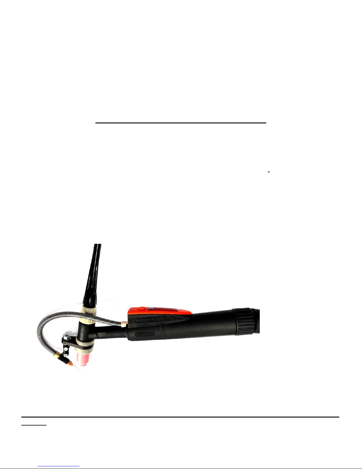
Using the Masterweld MWT3000-E Feeder with AWT300 Torch
Make sure the unit is correctly connected to the tig power source and power supplies etc. see above.
It is important to make sure that you have a very straight first few inches of wire before you start to
feed. The wire tensioner must be set so as not to crush the wire and just provide enough tension to
feed the wire reliably. The wire can be inched down the torch liner by the switch on the front panel.
The torch must be kept very straight when initially feeding the wire down to the head.
Sensitivity control & range switch –located within the MWT3000-E Feeder
The sensitivity knob also controls the start and stop of wire, this is located within the MW3000
Feeder. The sensitivity control always needs to be set below the actual welding amperage. Otherwise
the wire will never feed. The sensitivity control allows you to set the level of welding current that you
want the feed to start and stop at. So, for instance if you are welding at 200 amps and have some
slope down time pre-set on the power source, then if you set the sensitivity time at say 150 amps, the
feed will stop during the slope time at around 150 amps. This control is very useful for controlling the
start and stop during slope time.
The range switch alters the sensitivity control to give a 15-200A range or a 15-300A range.
This gives the operator better control of the sensitivity particularly on lower current.
Therefore, if welding below 200A we recommend setting the switch to the low range.
Note: values marked for sensitivity are only approximate.
Auto retract –located within the MWT3000-E Feeder
The auto retract reverses the wire drive to pull the wire out of the welding pool when the welding
current falls below that set on the sensitivity control. This function also works when pulsing the
welding current. However if auto retract is set too high when pulsing, the wire may be trying to retract
more than driving forward which will result in no wire feeding into the pool.

Welding with this equipment
Setting this up for the first time can be tricky, as there are so many variables involved. The wire feed
head position is probably the most critical part. You should aim to be feeding the wire into the edge of
the welding pool very close to the job, if it’s fed in too high or too close to the tungsten electrode there
is a risk of tungsten contamination. Ideally the leading edge of the welding pool is the perfect place to
feed in wire, so if you are travelling from right to left that’s the left hand side of the pool. For some
applications like TIG brazing it may be better to feed the wire in from the top side of the torch. The
back edge of the pool is normally an unsuitable position for feeding in wire.
Keeping the welding torch & liner as straight as possible is also very important.
When using this on a non-hand torch or automatic torch the above all still applies but the feed head
may need adapting to work correctly with a straight torch.
Setting the controls is quite easy once you understand the operation of each function. We
recommend studying the operation of these before trying to weld.
Faultfinding
1)Fault;
Wire feed doesn’t feed wire at all when welding.
Solutions;
Check feeder power supply is ok & wire will inch on the switch at the bottom of the panel, check
welding cable earth is connected correctly at rear of wire feeder, check sensitivity is set below
welding current level, check pool timer is set to off or low.
2)Fault;
Wire feed rollers turn but wire is slipping & not feeding correctly.
Solutions;
Wire maybe stuck in the end part of the wire feed head, check carefully. Check the welding torch &
liner are kept as straight as possible.
3)Fault;
Wire tends to freeze in pool at end of weld.
Solutions;
Set some down slope time on the power source & ensure that the sensitivity control is set just under
the welding current level. Or try setting the auto retract, increase this steadily until an optimum
condition is achieved.
4)Fault;
Power source working on pulse but no wire feeding
Solutions;
Refer to No 1 fault solution & check auto retract is set low or off. Try reducing pulse frequency or
increasing peak pulse width.

Maintenance
With the machine switched off
The operator should carry out daily checks of all cables and connections etc; any faults must be
reported to a competent person and the machine taken out of service until repaired.
Gas regulators should be regularly inspected by a qualified person according to health & safety
legislation.
Do not remove any machine panels before isolating the incoming supply.
Check all wire feeding parts carefully to ensure continued good wire feeding, replace worn gears &
rollers, and make sure all guards are replaced, do not inspect the feed mechanism with the
machine turned on as there is a risk of severe damage to fingers etc.
It is necessary for a comprehensive service inspection and test to be carried out at regular intervals
by a competent person and documented. This should be no less than every six months and sooner in
harsh operating conditions. This should include a documented electrical safety test.
Welding machines cannot & should not be ‘PAT’ tested.
If the machine is correctly maintained this machine should give a long trouble free life.
www.masterweld.co.uk
Table of contents
Other Masterweld Welding System manuals