mastro AJD0003/CCN User manual

Group
Service
w w w . v i r t u s n e t . d e
Virtus Group GmbH
Hüsers raße 53
59075 Hamm / Germany
%+49 (0)2381/973 71–0
7+49 (0)2381/973 71– 88

ES GB IT
ASADORES A GAS/ELECTRICOS
GAS/ELECTRIC ROASTERS
GRIGLIE A GAS / ELETTRICO
53030G13.94P
11/2017

2
Fig. 1
Fig. 4
Fig. 6
Fig. 3Fig. 2
OFF
Min.
Max.
B
A
A
B
A
C
D
A
A
B
C

3
ES
GB
IT
MANUAL DE INSTALACIÓN TÉCNICA DESTINADA AL INSTALADOR
ATENCIÓN
- Todas las regulaciones, transformaciones y
mantenimiento mencionados en el presente
manual, deben ser ejecutadas por un instalador
autorizado y de acuerdo a la reglamentación
vigente sobre aparatos a gas en el país donde se
instale.
- Este manual solo es válido si el símbolo del
país figura en la placa de características. En caso
contrario, es necesario recurrir a las instruccio-
nes técnicas que reunirán las indicaciones nece-
sarias para la adaptación del aparato a la legisla-
ción del país.
- Los aparatos, son únicamente de uso profe-
sional y deben ser utilizados por personal cuali-
ficado.
- Instalar el aparato en un lugar conveniente-
mente ventilado, para evitar la concentración de
sustáncias nocivas para la salud.
- Recuerde que las paredes adyacentes al aparato
deben resistir una temperatura mínima de 75ºC.
- Deben respetarse las salidas de los gases resul-
tantes de la combustión.
- Deben respetarse las entradas de aire de com-
bustión.
- Conservar este manual para futuras consultas.
ATTENTION
- All the regulations, transformations and
maintenance mentioned in this handbook must
be carried out by an authorised technician in
accordance to the regulations currently in
force regarding gas appliances in the country of
installation.
- This handbook is only valid if the country's
symbol appears on the plate of characteristics.
On the contrary, it will be necessary to resort to
the technical specifications which will include
the indications necessary to adapt the appliance
to the country's legislation.
- The appliances, are for professional use only
and must be used by qualified personnel
- Install the appliance in a properly ventilated
place, to avoid the concentration of injurious
substances for the health.
- Remember that the walls adjacent to the appli-
ance must withstand a minimum temperature of
75ºC.
- The gas outlets resulting from the combustion
must be respected.
- The air combustion inlets must be respected.
- Keep this manual for future reference.
TECHNICAL HANDBOOK FOR INSTALLATION
MANUALE TECNICO PER L'INSTALLATORE DI INSTALLAZIONE
ATTENZIONE
- Tutte le disposizioni, le modifiche e la manu-
tenzione di cui al presente manuale, deve essere
eseguita da un tecnico abilitato e secondo le
norme vigenti sugli apparecchi a gas nel paese
in cui viene installato lo è.
- Il presente manuale è valido solo se il comando
paese è sul piatto. In caso contrario, è necessario
utilizzare the istruzioni tecniche che soddisfano
le informazioni necessarie per adattare il dispo-
sitivo alla normativa.
- I dispositivi sono solo per uso professionale e
devono essere utilizzate da personale qualificato.
- Installare il dispositivo in un Invece ventilato,
per evitare la concentrazione di sostanze nocive
per la salute.
- Ricordate che la parete adiacente al dispositivo
deve sopportare una temperatura minima di 75 º
C.
- Va be rispettato gases from punti vendita della
combustione.
- Devono essere rispettate le entries aria di com-
bustione.
- Conservare il presente manuale di riferimento
per il futuro.
- Parti che sono stati protetti dal costruttore e il
suo agente non deve essere manipolato da l'ins-
tallatore o utente.

4
INSTALACIÓN DEL APARATO
Después de retirar el embalaje externo e interno del
aparato, ponerlo en su lugar de destino procurando que
su ubicación esté convenientemente ventilada (natural o
artificialmente) y sin corrientes de aire que pudieran
apagar el fuego de los quemadores durante su uso.
Las partes construidas en acero inoxidable están prote-
gidas con un film adherente para garantizar una perfecta
presentación, esta protección deberá retirarse en su
totalidad antes de poner en funcionamiento el aparato.
En los modelos con ruedas, estas solo sirven para trasla-
dar el parato pequeñas distancias.
Una vez ubicado el aparato debe frenarse accionando
los frenos de las ruedas.
En los modelos más grandes tener mucha precaución al
trasladarlos dada su altura e inestabilidad.
ATENCIÓN
NUNCA DEBE TRASLADARSE EL APARATO:
- CON LOS QUEMADORES ENCENDIDOS
- CON LAS ESPADAS CARGADAS
- CON LAS PUERTAS ABIERTAS
After removing the appliance's exterior and interior
wrapping, place it in its final emplacement making sure
that this emplacement is properly ventilated (natural or
artificially) and without drafts that could blow the fire
out of the burners whilst in use.
The parts made of stainless steel are protected with an
adherent film to guarantee a perfect presentation; this
protection must be totally removed before operating the
appliance.
In the models with wheels, these small distances only
serve to transfer the apparatus.
Once located the apparatus it must stop driving the
brakes of the wheels.
In the greatest models to have much precaution when
transferring given them to its height and instability.
ATTENTION
THE APPARATUS NEVER MUST MOVE:
- WITH THE IGNITED BURNERS
- WITH THE LOADED SWORDS
- WITH THE OPEN DOORS
INSTALLING THE APPLIANCE
CÁLCULO DEL CAUDAL TOTAL DE EVACUACIÓN REQUERIDO
CALCULATION OF THE TOTAL VOLUME OF REQUIRED EVACUATION
Dopo aver tolto la macchina per l'imballaggio esterno e
interno, mettete nella vostra destinazione garantire che
la sua posizione è ben ventilato (naturale o artificiale) e
bozze che potrebbe spegnere il fuoco del bruciatore
durante l'uso.
Le parti in acciaio inox sono protetti da un involucro di
plastica per garantire una perfetta presentazione, la
protezione dovrebbe essere ritirata nella sua interezza
prima di utilizzare l'apparecchio.
Il dispositivo deve essere di livello, sia in senso longitu-
dinale e trasversale.
Le gambe di supporto dei dispositivi sono regolati per
avere una distanza tra il suolo e l'unità di base di 150
mm. Questa distanza non si riduce in ogni caso.
INSTALLAZIONE DI APPLIANCE
CALCOLO DEL FLUSSO TOTALE NECESSARIO EVACUAZIONE

5
ES
GB
IT
CONEXIÓN AL GAS
ATENCIÓN
- Esta operación deberá ser efectuada por perso-
nal técnico autorizado por las reglamentaciones
vigentes sobre aparatos a gas o el que se requie-
ra para cada país.
- Comprobar que el gas y la presión a utilizar
corresponden con los valores que vienen indica-
dos en la placa de características incorporada al
aparato y para el cual ha sido calibrado por el
fabricante.
- Comprobar que todos los elementos que com-
ponen el aparato se encuentran perfectamente
situados y que debido al transporte no hayan
sufrido desajustes.
- Comprobar que el aparato esté perfectamente
ubicado, conforme a la legislación vigente para
cada país al que va destinado.
- Se aconseja colocar el aparato bajo una campa-
na extractora para asegurar la completa evacua-
ción de los gases de combustión y humos que-
mados en la fase de cocción, para evitar la con-
centración de sustáncias nocivas para la salud.
- Este aparato debe ser utilizado únicamente
para el propósito para el cual ha sido diseñado.
Cualquier otro uso sería impropio y peligroso.
- El aparato debe estar instalado a una distancia
mínima de 1.5 m. de cualquier material combus-
tible.
GAS / ELECTRICITY CONNECTION
ATTENTION
- This operation must be carried out by technical
staff authorised by the regulations currently in
force on gas appliances or that required for each
country.
- Verify that the gas and the pressure to be used
correspond with the values indicated on the plate
of characteristics attached to the appliance and
for which it was calibrated by the manufacturer.
- Verify that all the elements that correspond to
the appliance are perfectly placed and they have
not suffered misalignments due to transport.
- Verify that the appliance is properly placed,
according to the legislation currently in force for
each country it is destined to.
- It is advisable to place the appliance under an
extractor hood to ensure the complete evacua-
tion of the combustion gases and fumes whilst
cooking, to avoid the concentration of injurious
substances for the health.
- This appliance must be used exclusively for the
purpose for which it was designed for. Any
other use would be inappropriate and dangerous.
- The appliance must be installed at a minimum
distance of 1.5 m. from any combustible materi-
al.
COLLEGAMENTO GAS
ATTENZIONE
- Questa operazione deve essere eseguita da
personale qualificato autorizzato dalla normativa
esistente o gli apparecchi a gas che sono richiesti
per ciascun paese.
- Verificare che il gas e la pressione da utilizzare
corrispondono ai valori che sono indicati sulla
targhetta incorporata nel dispositivo e che è stato
tarato dal costruttore.
- Verificare che tutti gli elementi del dispositivo
sono in posizione ideale e che a causa di interru-
zioni di trasporto non hanno sofferto.
- Verificare che l'unità è perfettamente posi-
zionato, secondo il legislazione per ogni paese a
cui è destinato.
- Si consiglia di posizionare l'unità sotto il co-
fano per garantire l'evacuazione totale dei gas di
combustione e il fumo bruciato nella fase di
cottura, per evitare la concentrazione di sostanze
nocive per la salute.
- il dispositivo dovrebbe essere utilizzato solo
per lo scopo per il quale è stato progettato. Ogni
altro uso sarebbe improprio e pericoloso.
- L'apparecchio deve essere posto una distanza
minima di 1,5 m. di qualsiasi materiale combus-
tibile.

6
CONEXIÓN ELÉCTRICA
Modelo a gas
Los aparatos a gas están dotados de una toma de co-
rriente con un enchufe adecuado a la legislación corres-
pondiente, para alimentar el sistema motriz, este debe
ser conectado a una toma de corriente adecuada.
Antes de enchufar el aparato a la red, compruebe en la
placa de características el voltaje al que viene preparado
el asador. En caso de que no coincida con el de su insta-
lación deberá avisar al servicio técnico de su distribui-
dor para que efectúen el cambio de voltaje.
Modelo eléctrico
Antes de enchufar el aparato a la red, compruebe en la
placa de características el voltaje al que viene preparado
el asador. En caso de que no coincida con el de su insta-
lación deberá avisar al servicio técnico de su distribui-
dor para que efectúen el cambio de voltaje.
Los modelos eléctricos podrán conectarse a:
III - 380 V + neutro
III - 220 V
El aparato se suministra sin cable de alimentación.
En cualquier conexión a red eléctrica se deberá interca-
lar un interruptor principal, de fácil acceso, y que debe
cortar la distribución de energía de modo omnipolar y
los contactos de abertura deben tener entre sí una dis-
tancia mínima de 3 Mm. para cada polo.
El cable de alimentación no deberá tener características
inferiores a H07 RN-F, en todo caso deberá ajustarse a
la reglamentación vigente y tener una sección mínima
adecuada a la potencia del aparato.
No debe estar situado cerca de focos de calor y el am-
biente alrededor no debe superar la temp. de 50°C.
Para conectar el aparato deberemos proceder como
sigue:
1) Abrir la tapa lateral izquierda, retirando los tornillos
ELECTRIC CONNECTION
Gas model
The gas appliances are provided with a socket adapted
to the corresponding legislation, to supply the power
system, which must be connected to a suitable power
supply.
Before plugging in the appliance to the network, verify
on the plate of characteristics the voltage the roaster is
prepared for. In the event it does not coincide with that
of your installation, you must inform your distributor's
technical service for them to change the voltage.
Electric model
Before plugging in the appliance to the network, verify
on the plate of characteristics the voltage the roaster is
prepared for. In the event it does not coincide with that
of your installation, you must inform your distributor's
technical service for them to change the voltage. The
electric models may connect to:
III - 380 V + neutral
III - 220 V
The appliance is supplied without mains cable.
An all-pole breaker main switch of easy access must be
placed in any electrical network, and the opening con-
tacts must have a minimum distance between each other
of 3 Mm. for each pole.
The mains cable must not have characteristics lower
than H07 RN-F, in any case it must adjust to the regula-
tions currently in force and have a minimum section
adapted to the appliance's power.
It must not be placed near any source of heat and the
surrounding ambient must to exceed a temperature of
50°C.
To connect the appliance proceed as follows:
1) Remove the left side lid by removing the screws that
fix them.
COLLEGAMENTO ELETTRICO
Modello a gas
Gli apparecchi a gas sono dotati di una presa con spina
adatta per la legislazione corrispondente, per alimentare
il sistema motore, deve essere collegato a una presa di
corrente adeguata.
Prima di collegare l'apparecchio alla rete elettrica, con-
trollare la targhetta identificativa per la tensione alla
quale viene preparato il pollo. Se non corrisponde alla
tua installazione, devi informare il servizio tecnico del
tuo distributore in modo che possano cambiare la ten-
sione.
Modello elettrico
Prima di collegare l'apparecchio alla rete elettrica, con-
trollare la targhetta identificativa per la tensione alla
quale viene preparato il pollo. Se non corrisponde alla
tua installazione, devi informare il servizio tecnico del
tuo distributore in modo che possano cambiare la ten-
sione.
I modelli elettrici possono essere collegati a:
III - 380 V + neutro
III - 220 V
Il dispositivo è fornito senza cavo di alimentazione.
In qualsiasi collegamento alla rete, è necessario inserire
un interruttore principale facilmente accessibile e la
distribuzione di potenza deve essere interrotta in modo
onnipolare ei contatti di apertura devono avere una
distanza minima di 3 mm tra di loro. per ogni polo.
Il cavo di alimentazione non deve avere caratteristiche
inferiori a H07 RN-F, in tutti i casi deve essere con-
forme alle normative vigenti e avere una sezione mini-
ma adeguata alla potenza del dispositivo.
Non dovrebbe essere posizionato vicino a punti caldi e
l'ambiente circostante non dovrebbe superare la tempe-
ratura. di 50 ° C.

7
ES
GB
IT
que la fijan.
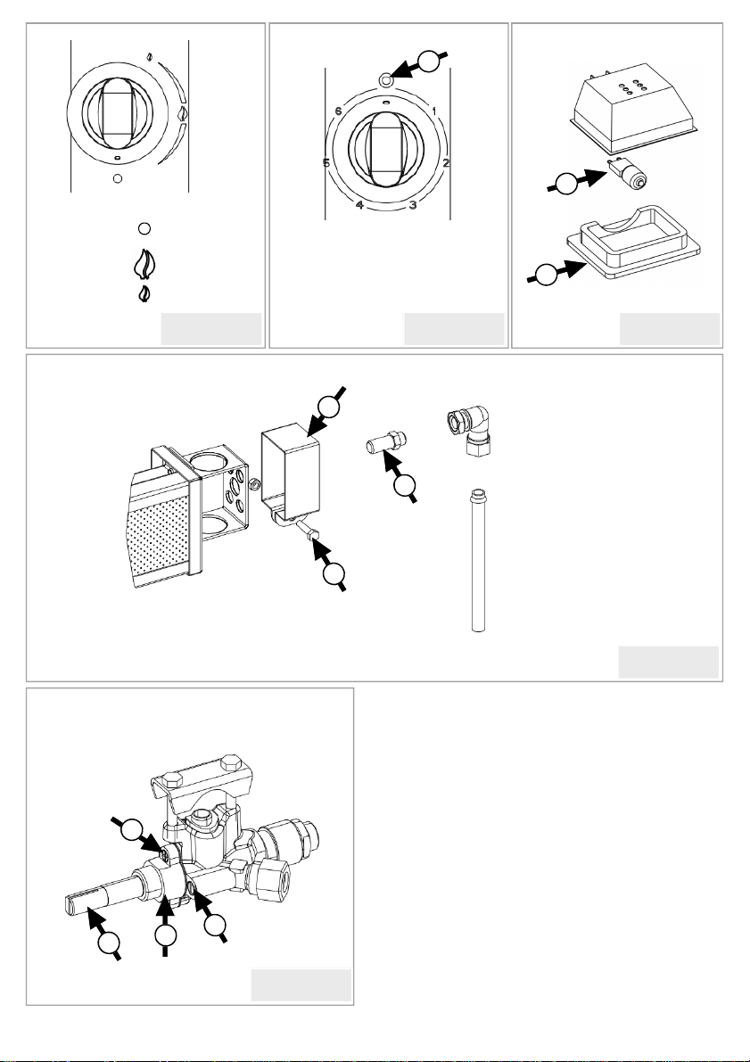
2) En la parte posterior baja del aparato se sitúa el pren-
saestopas de entrada, desenroscar la tuerca del prensaes-
topas para pasar el cable manguera hasta el interior del
aparato, y dirigirlo hasta los bornes de conexión situa-
dos en la parte posterior del aparato.
3) Aflojar con un destornillador los tornillos de los
bornes de conexión.
4) Insertar el extremo debidamente preparado de un
cable en su correspondiente alojamiento, comprobando
que se corresponde con su fase en el circuito, de acuer-
do con el esquema de conexión.
5) Apretar con el destornillador el tornillo del borne de
conexión correspondiente, comprobar que queda debi-
damente sujeto.
6) Repetir los pasos del 3 al 5 con el resto de los cables
y con el cable de toma de tierra.
ES INDISPENSABLE CONECTAR EL APARATO
A UNA TOMA DE TIERRA ADECUADA A LA
LEGISLACIÓN VIGENTE
Para ello, en el tablero de bornes se ha colocado un
borne, identificado con el símbolo correspondiente
9) Una vez conectados todos los cables, deslice el cable
manguera hasta el fondo de la máquina, mantenga el
cable apoyado en el fondo y finalmente fíjelo por medio
del prensaestopas dispuesto a tal fin, el cable no debe
quedar tensado en el interior del aparato, pero tampoco
demasiado suelto.
10) Situar de nuevo la tapa posterior del aparato y fijarla
con los tornillos correspondientes, hacer lo mismo con
la tapa lateral.
11) El otro extremo del cable deberá conectarse a la
toma eléctrica de acuerdo a las características de esta y
a la legislación vigente.
2) On the lower rear half of the appliance is the inlet
gland, unscrew the gland's nut in order to insert the
piped cable inside the appliance and direct it to the
terminal connections located on the rear side of the
appliance.
3) Loosen the screws of the terminal connections with a
screw driver.
4) Insert the duly prepared end of a cable with its corre-
sponding housing, verifying it corresponds to is phase
in the circuit, according to the connection diagram.
5) Tighten with the screw driver the screw of the corre-
sponding connection, and verify it is duly secured.
6) Repeat steps 3 to 5 with the rest of the cables and
with the earth connection cable.
IT IS INDISPENSABLE TO CONNECT THE AP-
PLIANCE TO A GROUND CONNECTION
WHICH COMPLIES WITH THE LEGISLATION
CURRENTLY IN FORCE
Therefore, a connection has been placed on the connec-
tion board, identified with the corresponding symbol.
9) Once all the cables are connected, slide the piped
cable to the end of the machine, keep the cable resting
on the bottom and finally fix it by means of the gland
provided for this purpose, the cable must not be left too
tight or too lose inside the appliance.
10) Place the rear lid on again and fix it with the corre-
sponding screws, and do the same with the side lid.
11) The other end of the cable must be connected to the
electric supply according to its characteristics and the
legislation currently in force.
Per connettere il dispositivo dobbiamo procedere come
segue:
1) Aprire il coperchio laterale sinistro, rimuovendo le
viti che lo fissano.
2) Nella parte inferiore della parte posteriore del dispo-
sitivo, posizionare il pressacavo dell'ingresso, svitare il
dado dal pressacavo per far passare il cavo del flessibile
all'interno del dispositivo e dirigerlo verso i terminali di
connessione situati sul retro del dispositivo.
3) Allentare le viti dei terminali di connessione con un
cacciavite.
4) Inserire l'estremità appropriatamente preparata di un
cavo nell'alloggiamento corrispondente, verificando che
corrisponda alla sua fase nel circuito, secondo lo sche-
ma di collegamento.
5) Stringere la vite del terminale di connessione corris-
pondente con il cacciavite, verificare che sia corretta-
mente fissata.
6) Ripetere i passaggi da 3 a 5 con il resto dei cavi e con
il filo di terra.
È INDISPENSABILE COLLEGARE L'APPAREC-
CHIO AD UNA PRESA DI TERRA ADATTA AL-
LA NORMATIVA ATTUALE
Per fare questo, un terminale è stato posizionato sulla
morsettiera, identificata con il simbolo corrispondente
9) Una volta collegati tutti i cavi, far scorrere il cavo del
flessibile sul fondo della macchina, mantenere il cavo
appoggiato sul fondo e infine fissarlo tramite il pressa-
cavo fornito a tale scopo, il cavo non deve essere teso
all'interno del dispositivo , ma né troppo sciolto.
10) Rimontare il coperchio posteriore dell'apparecchio e
fissarlo con le viti corrispondenti, fare lo stesso con il
coperchio laterale.
11) L'altra estremità del cavo deve essere collegata alla
presa elettrica secondo le caratteristiche di questa e
della legislazione vigente.

8
CONEXIÓN AL GAS
El aparato está preparado para conectarlo con la fuente
de alimentación del gas a la derecha del mismo. Las
posibilidades de conexión son las siguientes:
Conexión rígida entre la red y el aparato:
En cualquier conexión a red deberá intercalarse una
válvula de corte de suministro entre el aparato y la red.
El tipo de tubería a emplear podrá ser de cobre o de
acero estirado sin soldadura.
Dicha conexión debe ser mediante enlace de unión.
Conexión flexible entre la red y el aparato:
El tubo flexible deberá cumplir con las homologaciones
correspondientes.
El tubo flexible no deberá tener una curvatura demasia-
do pequeña o estar estrangulado.
Conexión a bombonas de GLP:
Las bombonas de gas se colocaran en el exterior, a cielo
abierto u otra ubicación adecuada (excepto en asadores
con armario portabombonas)
Toda bombona estará dotada de un regulador de presión
fijo.
El tubo flexible deberá cumplir con las homologaciones
correspondientes y será como máximo de 1.5 m.
La conexión entre el aparato y el tubo flexible se efec-
tuará mediante la boquilla adecuada, y con las bridas de
fijación adecuadas para garantizar la estanqueidad de la
conexión.
Una vez instaladas las bombonas, se verificará el per-
fecto ajuste de las mismas con cada uno de los regula-
dores. Al iniciar la cocción se accionarán las palancas
de los reguladores de las bombonas, cerrándose las
mismas al finalizar el trabajo.
ES MUY IMPORTANTE EL CAMBIO DEL TUBO
FLEXIBLE UNA VEZ AL AÑO
CONNECTION
The appliance is prepared to be connected to the gas
power supply on its right side. The connection possibili-
ties are the following:
Rigid connection between the network and the appli-
ance:
In any connection to the network a cut-off valve must
be inserted between the appliance and the network.
The type of pipe to use may be copper or non-welded
drawn steel.
This connection must be by means of coupling.
Flexible connection between the network and the
appliance:
The flexible pipe must comply with the corresponding
certifications.
The curvature of the flexible pipe must not be too small
or too throttled.
Connection to GLP gas cylinders:
The gas cylinders will be placed on the exterior, open-
cut or any other suitable location (except roasters with a
cupboard for gas cylinders)
The gas cylinder must be provided with a fixed pressure
regulator.
The flexible pipe must comply with the corresponding
certification and will be 1.5 m at the most.
The connection between the appliance and the flexible
pipe must be by means of a suitable nozzle and with the
right fixing clamp in order to guarantee the appropriate
sealing of the connection.
Once the gas cylinders have been installed, they must be
perfectly adjusted to each of the regulators. When start-
ing the cooking process the leavers of the gas cylinder
regulators must be opened, and then closed when fin-
ished the work.
IT IS VERY IMPORTANT TO CHANGE THE
FLEXIBLE TUBE ONCE EVERY YEAR
CONNESSIONE AL GAS
L'apparecchio è pronto per essere collegato alla fonte di
alimentazione del gas a destra dell'apparecchio. Le
possibilità di connessione sono le seguenti:
Connessione rigida tra la rete e il dispositivo:
In qualsiasi connessione alla rete, è necessario inserire
una valvola di interruzione dell'alimentazione tra l'ap-
parecchio e la rete.
Il tipo di tubo da utilizzare può essere in rame o acciaio
trafilato senza saldatura.
Questa connessione deve essere attraverso il collega-
mento sindacale.
Connessione flessibile tra la rete e il dispositivo:
Il tubo flessibile deve essere conforme alle omologazio-
ni corrispondenti.
Il tubo flessibile non dovrebbe avere una curvatura
troppo piccola o essere strangolato.
Collegamento ai cilindri GPL:
Le bombole di gas saranno collocate all'esterno, all'aria
aperta o in un'altra posizione adatta (tranne nelle griglie
con un armadio della pompa)
Ogni cilindro sarà dotato di un regolatore di pressione
fisso.
Il tubo flessibile deve essere conforme alle omologazio-
ni corrispondenti e avere un massimo di 1,5 m.
Il collegamento tra l'apparecchio e il tubo flessibile sarà
realizzato attraverso l'apposito ugello e con le apposite
flange di fissaggio per garantire la tenuta della connes-
sione.
Una volta installati i cilindri, la regolazione perfetta di
essi verrà verificata con ciascuno dei regolatori. All'ini-
zio della cottura le leve dei regolatori dei cilindri saran-
no attivate chiudendole alla fine del lavoro.
È MOLTO IMPORTANTE IL CAMBIAMENTO
DEL TUBO FLESSIBILE UNA VOLTA UN ANNO

9
ES
GB
IT
CAMBIO DE GAS
Todos nuestros aparatos pueden funcionar con GLP o
GN, de todos modos de fábrica se suministran prepara-
dos para GLP (salvo a petición del cliente). A fin de
facilitar su adaptación a GN, se incluye un juego de
inyectores adicional para este gas.
Para adaptar el funcionamiento del aparato a otro tipo
de gas (distinto de aquel para el cual ha sido entregado)
es necesario lo siguiente:
- En los quemadores: el cambio de los inyectores.
- No es necesaria la regulación del aire primario.
Recuerde que una vez realizadas las operaciones de cambio de gas, debe substituirse la etiqueta del tipo
de gas que está fijada junto a la acometida por la correspondiente al nuevo tipo de gas. Esta se incluye
en la documentación adjunta al aparato.
GAS CHANGE
All our devices may operate with GLP or GN, neverthe-
less they are prepared from the factory for GLP (except
if requested by the client). With the aim of facilitating
their adaptation to GN, a set of additional injectors for
this gas are included.
To adapt the operation of the appliance to another type
of gas (different from that for which it was delivered)
the following is necessary:
- On the burners: the change of the injectors.
- The regulation of the primary air is not necessary.
Remember that once the change of gas operation has concluded, the label indicating the type of gas
placed next to the connection must be replaced by the corresponding label with the new type of gas.
This is included in the documentation provided with the appliance.
CAMBIO DI GAS NEL TOP
Tutti i nostri apparecchi possono essere eseguiti a GPL
o GN, comunque fabbrica fornito pronto per il GPL
(tranne che a richiesta). Al fine di facilitare l'adegua-
mento alle GN, include un set di iniettori per questo gas.
Per adeguare il funzionamento del dispositivo ad un
altro tipo di gas (diverso da quello per cui è stato con-
segnato) è necessario:
- Nei bruciatori: il cambio degli iniettori.
- La regolazione dell'aria primaria non è necessaria.
Ricordate che dopo aver completato le operazioni di scambio di gas, è sostituito l'etichetta sul tipo di gas
che si trova accanto alla connessione con l'indicazione del nuovo tipo di gas. Questo è incluso nella
documentazione che accompagna il prodotto.

10
LOS QUEMADORES
Regulación del gas en los quemadores (Fig. 4 )
THE BURNERS
Regulating the gas on the burners (Fig. 4)
I BRUCIATORI
Regolazione del gas nei bruciatori (figura 4)
En la figura se puede observar un quemador.
Para adaptar el quemador a otro tipo de gas deberemos
proceder como sigue:
1) Cerrar la llave general de paso del gas.
2) Abrir la tapa lateral retirando los tornillos que la
fijan.
3) Aflojar el tornillo (B) para poder retirar el aireador
(C).
4) Desenroscar con una llave fija el inyector (A) que
debemos sustituir según nos convenga, GN mayor paso,
GLP menor paso.
5) Proceder de modo inverso para volver a montar el
inyector (A).
6) Situar de nuevo el aireador (C) regulando el flujo de
aire correspondiente al inyector montado.
7) Fijar el aireador mediante el tornillo (B).
8) Volver a situar la tapa lateral derecha, con los torni-
llos que la fijan.
9) Abrir la llave general de paso del gas y comprobar la
correcta combustión en el quemador.
The figure shows a burner.
To adjust the burner to another type of gas to proceed as
follows:
1) Close the general stopcock of gas.
2) Open the side cover by removing the screws that hold
it.
3) Loosen the screw (B) to remove the aerator (C).
4) Screw with a wrench the injector (A) we must repla-
ce as needed us, GN major step, GLP smaller pitch.
5) Proceed as reverse to reassemble the nozzle (A).
6) Place again aerator (C) regulating the flow of air for
the injector mounted.
7) Set the aerator with the screw (B).
8) Reposition the top right side, with the screws that
secure.
9) Open the general stopcock of gas and check for pro-
per combustion in the burner.
Nella figura puoi vedere un bruciatore.
Per adattare il bruciatore a un altro tipo di gas, proce-
dere come segue:
1) Chiudere la valvola di intercettazione generale del
gas.
2) Aprire il coperchio laterale rimuovendo le viti che lo
fissano.
3) Allentare la vite (B) per rimuovere l'aeratore (C).
4) Svitare l'iniettore (A) con una chiave fissa che dob-
biamo sostituire se necessario, passo GN più grande,
passo GPL più piccolo.
5) Procedere nell'ordine inverso per rimontare l'iniettore
(A).
6) Riposizionare l'aeratore (C) che regola il flusso d'aria
corrispondente all'iniettore montato.
7) Fissare l'aeratore usando la vite (B).
8) Riposizionare il coperchio laterale destro, con le viti
che lo fissano.
9) Aprire la valvola generale di intercettazione del gas e
controllare la corretta combustione nel bruciatore.

11
ES
GB
IT
Periódicamente, al notar una dureza en el giro de las
válvulas, deberá procederse al engrase de las mismas y
para ello deberemos descubrir las válvulas, procediendo
de la forma siguiente:
1) Sacar los 2 tornillos frontales (B) de la válvula.
2) Sacar la caperuza frontal de aluminio (C).
3) Tirar del eje (D), descubriendo el asiento de válvula .
4) Limpiar el cono con la ayuda de un paño suave y
diluyente.
5) Engrasar con grasa KLÜBER (ref.3035) asegurando
que el paso de gas no está obturado.
6) Girar repetidas veces el eje del grifo con su corres-
pondiente mando.
7) Montar de nuevo todas las piezas.
Esta regulación debe hacerse solo cuando se ha efectua-
do un cambio de gas con respecto al original de fábrica.
Procederemos de la forma siguiente:
1) Cerrar la llave general de paso del gas.
2) Retirar los mandos de las válvulas
3) Regular el caudal abriendo o cerrando el paso actuan-
do con un destornillador plano sobre el tornillo (A).
4) Repetir esta operación en todas la válvulas.
5) Montar de nuevo los mandos en las válvulas.
LAS VÁLVULAS DE SEGURIDAD
Regulación del gas en las válvulas de seguridad (Fig. 6 )
Mantenimiento de las válvulas de seguridad (Fig. 6 )
When noticing that the valves are hard to turn you must
periodically grease them, proceeding as follows:
1º) Remove the two front screws (B) from the valve.
2º) Remove the aluminium front cap (C).
3º) Pull the axle (D), exposing the valve's entry.
4º) Clean the cone with a soft cloth and diluents.
5º) Grease with KLÜBER (ref.3035) grease assuring
that the gas inlet is not blocked.
6º) Turn the tap's axle several times with its correspond-
ing control.
7º) Assembly all the pieces again.
This regulation must only be performed when having
changed the gas that the appliance came with originally
from the factory.
We must proceed as follows:
1º) Close the general gas shut-off valve.
2º) Remove the controls from the valves
3º) Regulate the flow with a flat screwdriver over the
screw (A).
4º) Repeat the operation on all the valves.
5º) Fix the controls back on the valves.
SAFETY VALVES
Regulating the gas in the safety valves (Fig. 6)
Maintenance of the safety valves (Fig. 6 )
Periodicamente, quando si nota una durezza nella rota-
zione delle valvole, dovrebbero essere lubrificati e per
questo dobbiamo scoprire le valvole, procedendo come
segue:
1) Rimuovere le 2 viti anteriori (B) dalla valvola.
2) Rimuovere il cappuccio anteriore in alluminio (C).
3) Tirare l'albero (D), scoprendo la sede della valvola.
4) Pulire il cono con l'aiuto di un panno morbido e
sottile.
5) Lubrificare con grasso KLÜBER (rif. 3035) assicu-
randosi che il passaggio del gas non sia intasato.
6) Ruotare ripetutamente l'albero del maschio con la
relativa manopola.
7) Rimontare tutte le parti.
Questo regolamento deve essere fatto solo quando è
stata apportata una modifica del gas rispetto alla fab-
brica originale. Noi procederemo come segue:
1) Chiudere la valvola di intercettazione generale del
gas.
2) Rimuovere i comandi della valvola
3) Regolare il flusso aprendo o chiudendo il passaggio
agendo con un cacciavite piatto sulla vite (A).
4) Ripetere questa operazione su tutte le valvole.
5) Montare nuovamente i comandi sulle valvole.
LE VALVOLE DI SICUREZZA
Regolazione del gas nelle valvole di sicurezza (Fig. 6)
Manutenzione delle valvole di sicurezza (Fig. 6)

12
En la figura se puede observar el foco halógeno.
Para cambiar la bombilla del foco halógeno deberemos
proceder como sigue:
1) Cerrar el interruptor principal.
2) Con mucha precaución retirar el cristal del foco (A).
4) Proceder al cambio de la bombilla (B) por una de
idénticas características.
5) Proceder de modo inverso para volver a montar el
foco halógeno.
LAS LUCES HALÓGENAS
Cambio de la bombilla halógena (Fig. 3 )
The figure shows a halogen light.
To change the bulb of the halogen light we must pro-
ceed as follows:
1) Close the main switch.
2) Remove the glass (A).
4) Proceed to change the bulb (B) for one of identical
characteristics.
5) Proceed in the reverse way to assembly the halogen
light again.
HALOGEN LIGHTS
Changing a halogen bulb (Fig. 3)
Nella figura puoi vedere la lampadina alogena.
Per cambiare la lampadina alogena, dobbiamo proce-
dere come segue:
1) Chiudere l'interruttore principale.
2) Rimuovere con attenzione il vetro dalla lampadina
(A).
4) Procedere al cambio della lampadina (B) per una
delle caratteristiche identiche.
5) Procedere in modalità inversa per rimontare la lam-
padina alogena.
LE LUCI ALOGENE
Sostituzione della lampadina alogena (figura 3)

13
ES
GB
IT
IMPORTANTE
Nos encontramos con el aparato a punto de ser
puesto en marcha, no obstante deberá tomarse
una última precaución y será el análisis de fugas.
A tal fin y con la llave general de paso del gas
cerrada, se cubrirán las partes de unión y todas
aquellas que hayan sido manipuladas, con agua
jabonosa, espuma o detector de gases, seguida-
mente abriremos la llave general de paso del
gas.
En el caso de apreciar alguna fuga se cerrará
inmediatamente la llave general de paso del gas,
y se procederá a la reparación de la fuga detecta-
da, volviendo seguidamente a efectuar la misma
comprobación desde el inicio hasta conseguir
una completa estanqueidad del circuito.
IMPORTANT
We have the appliance ready to be started; nev-
ertheless a last precaution must be taken which
is the leakage analysis.
For this purpose and with the general gas cut-off
valve closed, the junction parts as well as all of
those part that have been handled must be cov-
ered with soap water, foam or gas detector, and
them open the gas general shut-off valve.
In the event of finding a leakage the general gas
shut-off valve must be closed and the leakage
detected must be repaired; the same verification
must be carried out again until achieving the
complete sealing of the circuit.
IMPORTANTE
Ci troviamo con il dispositivo che sta per essere
avviato, tuttavia deve essere presa un'ultima
precauzione e sarà l'analisi delle perdite.
Per questo scopo e con la valvola di intercetta-
zione generale per il gas chiuso, le parti comuni
e tutte quelle che sono state maneggiate devono
essere coperte con acqua saponata, schiuma o
rilevatore di gas, quindi apriremo la valvola
generale di intercettazione del gas.
Nel caso in cui si apprezzi una perdita, la valvo-
la generale di intercettazione del gas verrà
chiusa immediatamente e la perdita rilevata
verrà riparata, quindi lo stesso controllo verrà
eseguito dall'inizio fino al raggiungimento della
completa tenuta del circuito.

14
USE AND MAINTENANCE INSTRUCTIONS FOR THE USER
INSTRUCCIONES DE USO Y MANTENIMIENTO PARA EL USUARIO
ISTRUZIONI PER L'USO E LA MANUTENZIONE PER L'UTENTE
ATENCIÓN
- Todas las regulaciones, transformaciones y
mantenimiento mencionados en el presente
manual, deben ser ejecutadas por un instalador
autorizado y de acuerdo a la reglamentación
vigente sobre aparatos a gas en el país donde se
instale.
- Este manual solo es válido si el símbolo del
país figura en la placa de características. En caso
contrario, es necesario recurrir a las instruccio-
nes técnicas que reunirán las indicaciones nece-
sarias para la adaptación del aparato a la legisla-
ción del país.
- Los aparatos, son únicamente de uso profe-
sional y deben ser utilizados por personal cuali-
ficado.
- Instalar el aparato en un lugar conveniente-
mente ventilado, para evitar la concentración de
sustáncias nocivas para la salud.
- Recuerde que las paredes adyacentes al aparato
deben resistir una temperatura mínima de 75ºC.
- Deben respetarse las salidas de los gases resul-
tantes de la combustión.
- Deben respetarse las entradas de aire de com-
bustión.
- Conservar este manual para futuras consultas.
ATTENZIONE
- Tutti i regolamenti, le trasformazioni e le ma-
nutenzioni menzionate nel presente manuale
devono essere eseguite da un installatore auto-
rizzato e in conformità alle normative vigenti
sugli apparecchi a gas del paese in cui è installa-
to.
- Questo manuale è valido solo se il simbolo del
paese appare sulla targhetta dei dati. Altrimenti,
è necessario ricorrere alle istruzioni tecniche che
raccoglieranno le indicazioni necessarie per
l'adeguamento del dispositivo alla legislazione
del paese.
- I dispositivi sono solo per uso professionale e
devono essere utilizzati da personale qualificato.
- Installare l'apparecchio in un luogo adeguata-
mente ventilato, per evitare la concentrazione di
sostanze nocive per la salute.
- Ricordare che le pareti adiacenti all'apparec-
chio devono sopportare una temperatura minima
di 75 ° C.
- Le uscite dei gas risultanti dalla combustione
devono essere rispettate.
- Le prese d'aria di combustione devono essere
rispettate.
- Conservare questo manuale per riferimento
futuro.
ATTENTION
- All the regulations, transformations and
maintenance mentioned in this handbook must
be carried out by an authorised technician in
accordance to the regulations currently in
force regarding gas appliances in the country of
installation.
- This handbook is only valid if the country's
symbol appears on the plate of characteristics.
On the contrary, it will be necessary to resort to
the technical specifications which will include
the indications necessary to adapt the appliance
to the country's legislation.
- The appliances, are for professional use only
and must be used by qualified personnel
- Install the appliance in a properly ventilated
place, to avoid the concentration of injurious
substances for the health.
- Remember that the walls adjacent to the appli-
ance must withstand a minimum temperature of
75ºC.
- The gas outlets resulting from the combustion
must be respected.
- The air combustion inlets must be respected.
- Keep this manual for future reference.

15
ES
GB
IT
PUESTA EN MARCHA DE ASADOR
Para poner en marcha el asador debe proceder de la
forma siguiente:
1) Encender los quemadores ( a gas o eléctricos).
2) Poner en marcha el motor encargado del giro de las
espadas.
3) Cargar el asador con las espadas.
ATENCIÓN
- ES MUY IMPORTANTE TENER EN CUENTA
QUE JAMÁS SE DEBE TENER EL ASADOR CON
LOS QUEMADORES EN MARCHA SIN VIANDAS
PARA ASAR Y CON LOS CRISTALES CERRADOS.
- SE DEBEN PONER EN MARCHA LOS QUEMA-
DORES ( A GAS O ELÉCTRICOS) EMPEZANDO
SIEMPRE POR EL INFERIOR, Y SEGÚN LAS NE-
CESIDADES DE CADA MOMENTO ENCENDER
MÁS QUEMADORES.
START-UP OF THE ROASTER
INIZIO DI ROTISSERIE
En los modelos con ruedas, estas solo sirven para
trasladar el aparato pequeñas distancias.
Una vez ubicado el aparato debe frenarse accionando
los frenos de las ruedas.
En los modelos más grandes tener mucha precaución
al trasladarlos dada su altura e inestabilidad.
ATENCIÓN
NUNCA DEBE TRASLADARSE EL APARATO:
- CON LOS QUEMADORES ENCENDIDOS
- CON LAS ESPADAS CARGADAS
- CON LAS PUERTAS ABIERTAS
To start-up the roaster you must proceed as follows:
1) Turn-on the burners (gas or electric).
2) Start the motor in charge of turning the spears.
3) Load the roaster with the spears.
ATTENTION
- IT IS VERY IMPORTANT TO TAKE INTO CON-
SIDERATION THAT YOU SHOULD NEVER
LEAVE THE ROASTER WITH THE BURNERS ON
WITHOUT THE ROASTING SPEARS AND THE
WINDOWS CLOSED.
- THE BURNERS SHOULD ALWAYS BE LIGHT
(GAS OR ELECTRIC) STARTING FROM THE BOT-
TOM AND MORE BURNERS SHOULD BE LIGHT
ACCORDING TO THE REQUIREMENTS.
In the models with wheels, these small distances only
serve to transfer the apparatus.
Once located the apparatus it must stop driving the
brakes of the wheels.
In the greatest models to have much precaution when
transferring given them to its height and instability.
ATTENTION
THE APPARATUS NEVER MUST MOVE:
- WITH THE IGNITED BURNERS
- WITH THE LOADED SWORDS
- WITH THE OPEN DOORS
Per avviare la griglia, procedere come segue:
1) Accendi i bruciatori (a gas o elettrici).
2) Avviare il motore responsabile della rotazione delle
spade.
3) Caricare la griglia con le spade.
ATTENZIONE
- È MOLTO IMPORTANTE TENER CONTO DI
NON AVERE MAI LA GRIGLIA CON I BRUCIA-
TORI IN FUNZIONE SENZA VIANDA ALLA GRI-
GLIA E CON I CRISTALLI CHIUSI.
- I BRUCIATORI DEVONO ESSERE COMINCIATI
(GAS O ELETTRICI) PER INIZIARE SEMPRE AT-
TRAVERSO IL BASSO, E SECONDO LE ESI-
GENZE DI OGNI MOMENTO IGNITE PIÙ BRU-
CIATORI.
Nei modelli con ruote, queste servono solo per sposta-
re il dispositivo su piccole distanze.
Una volta posizionato il dispositivo, è necessario
arrestarlo premendo i freni delle ruote.
Nei modelli più grandi fare molta attenzione quando si
spostano, data la loro altezza e instabilità.
ATTENZIONE
L'APPARECCHIO NON DEVE ESSERE MAI
TRASFERITO:
- CON IL BRUCIATORE LIT
- CON SPADE CARICATE
- CON LE PORTE APERTE

16
1) Open the gas cylinder's general gas shut-off valve or
the regulator's lever.
2) With the control of the safety valve corresponding to
the burner we wish to light in OFF position, slightly
press the control and turn it against the clock until
reaching the position MAX.
3) Press again until the end and keep it pressed at the
same time as we light the burner with a flame.
4) Keep it pressed for the flame to activate the safety
thermocouple (approximately 15 seconds, until when
letting go the flame of the burner stays alight).
5) As from this moment we can regulate the flame
between the positions of maximum and minimum.
Remember that to do so you must slightly press the
control as this is blocked for safety reasons.
6) To turn it off, place the control on OFF position.
START-UP THE ROASTERS
Start-up of the gas roasters by means of safety valve (Fig. 1)
1) Abrir la llave general de paso del gas o la palanca del
regulador de la bombona de gas.
2) Con el mando de la válvula de seguridad correspon-
diente al quemador que queremos encender en posición
OFF, pulsar ligeramente el mando y hacerlo girar en
sentido antihorario hasta la posición MAX.
3) Presionar nuevamente hasta el fondo y mantenerlo
presionado al tiempo que encendemos el quemador con
una llama.
4) Mantenerlo presionado para que la llama active el
termopar de seguridad (unos 15 segundos, hasta que al
soltarlo se mantenga la llama del quemador encendida).
5) A partir de este momento podemos regular el fuego
entre las posiciones de máximo y mínimo. Recuerde
que para ello debe presionar ligeramente el mando ya
que este queda bloqueado como medida de seguridad.
6) Para su apagado, colocar el mando en la posición
OFF.
ENCENDIDO DE LOS ASADORES
Encendido de los asadores a gas mediante válvula de seguridad (Fig. 1)
1) Aprire la valvola generale di intercettazione del gas o
la leva dell'acceleratore della bombola del gas.
2) Con il controllo della valvola di sicurezza corrispon-
dente al bruciatore che vogliamo illuminare in posizione
OFF, premere leggermente la manopola e ruotarla in
senso antiorario fino alla posizione MAX.
3) Premere nuovamente verso il basso e tenerlo premuto
mentre si accende il bruciatore con una fiamma.
4) Tenere premuto in modo che la fiamma attivi la
termocoppia di sicurezza (circa 15 secondi, finché la
fiamma del bruciatore non si accende quando viene
rilasciata).
5) Da questo momento possiamo regolare il fuoco tra le
posizioni di massimo e minimo. Ricordare che per fare
ciò è necessario premere leggermente il comando poi-
ché è bloccato come misura di sicurezza.
6) Per spegnerlo, posizionare la manopola in posizione
OFF.
ACCENSIONE DELLE GRIGLIE
Accensione delle griglie a gas mediante una valvola di sicurezza (Fig. 1)
ATENCIÓN
Antes de encender los quemadores comprobar que están limpios, y que en la bandeja recogegrasas no quedan
restos de aceite o grasas que pudieran provocar un incendio.
ATTENTION
Before igniting the burners to verify that they are clean, and that in the tray of greasy is not rest of oil or greasy
that could bring about a fire.
ATTENZIONE
Prima di accendere i bruciatori, controllare che siano puliti e che non vi siano tracce di olio o grasso nel vassoio
che potrebbero causare un incendio.

17
ES
GB
IT
1) Connect the main switch.
2) Turn clockwise the control corresponding to the glass
ceramic resistance we wish to use, until reaching the
desired position, between 1 and 6.
3) The pilot (A) located over the control will light when
the ceramic glass resistance is in operation.
4) For its disconnection, place the control in the upper
vertical position, posting the red pilot light (A).
Start-up of the electric roasters (Fig. 2)
1) Conectar el interruptor principal.
2) Girar en sentido horario el mando correspondiente a
la resistencia vitrocerámica que queremos utilizar, hasta
la posición deseada entre la 1 y la 6.
3) El piloto (A) situado sobre el mando se encenderá
cuando la resistencia vitrocerámica esté en funciona-
miento.
4) Para su desconexión, colocar el mando en la posición
vertical superior, dirigido hacia el piloto rojo (A).
Encendido de los asadores eléctricos (Fig. 2)
1) Collegare l'interruttore principale.
2) Ruotare in senso orario la manopola corrispondente
alla resistenza vetroceramica che vogliamo utilizzare,
nella posizione desiderata tra 1 e 6.
3) La spia luminosa (A) sul controllo si accenderà
quando il piano di cottura in ceramica è in funzione.
4) Per scollegare, posizionare il comando nella posi-
zione verticale superiore, diretto verso la luce pilota
rossa (A).
Accensione dei grill elettrici (Fig. 2)

18
CARGA DE LAS ESPADAS CON POLLOS
LOADING THE SPEARS WITH CHICKENS
SPADA DI CARICO CON I POLLI
ESPADAS 3 POLLOS PARA:
SERIE S SPEARS 3 CHICKENS FOR:
S SERIES 3 SPADE DI POLLO PER:
SERIE S
ATENCIÓN
Los recambios necesarios serán determinados por personal técnico.
ATTENTION
The necessary spare parts will be determined by technical personnel.
ATTENZIONE
I pezzi di ricambio necessari saranno determinati dal personale tecnico.

19
ES
GB
IT
Es aconsejable que el usuario tenga programado un plan
de mantenimiento anual con el servicio oficial, solo así
dispondrá de un aparato en óptimas condiciones de
funcionamiento en todo momento.
La manipulación de dichos equipos se efectuará por
personal autorizado por el fabricante.
Cuando el usuario detecte la más mínima avería se
pondrá en contacto con el DISTRIBUIDOR OFICIAL
de nuestra marca, con el fin de que proceda a su repara-
ción o puesta a punto.
LIMPIEZA, CONSERVACIÓN DEL APARATO
Dos son las formas de limpieza, una primera parcial o
diaria y una segunda total o semanal.
En general para estos menesteres no se usaran detergen-
tes abrasivos existiendo en el mercado un gran número
de productos que disuelven las grasas y demás materias
orgánicas sin dañar la estructura del aparato.
No se procederá jamás a la limpieza por chorro a pre-
sión.
Nuestros aparatos están concebidos de forma que sean
fácilmente desmontables y accesibles para su conserva-
ción y limpieza.
Quemadores.
Asegurar una perfecta limpieza de los quemadores ,
limpiando sus superficies.
Superficies de acero inoxidable.
Los aparatos están construidos en acero inoxidable,
material de excelente calidad y durabilidad. Mantenien-
do una limpieza diaria de estas partes con detergente se
mantendrán en perfecto estado. No utilice productos
abrasivos que podrían rayar estas superficies.
MANTENIMIENTO
The user should be advised to have a programmed annu-
al maintenance plan with the official service to assure
having the appliance in perfect operating conditions at
any moment.
The manipulation of these machines will only take place
by maintenance staff authorized by the manufacturer.
If the customer finds the smallest failure he will get in
contact with the 0FICIAL DISTRIBUTOR of the brand
in order to get the problem solved.
that he comes to his repair or completion.
CLEANING AND CONSERVATION
There are two ways of cleaning, the first being partial or
daily, the second full or weekly. Abrasive detergents
should generally not be used as a great number of prod-
ucts dissolving fats and other organic matters not dam-
aging the appliances structure can be found in the mar-
ket. Beware of cleaning with pressure spurt.
Our appliances are conceived to be easily dismantled
and accessible for their cleaning and conservation.
Burners
Cleaning the burner’s surface will assure a perfect neat-
ness.
Stainless steel surfaces
The appliances are made of stainless steel, a high quali-
ty material of excellent durability.
To maintain these parts in perfect conditions, a daily
cleaning with detergent is necessary. Never use abrasive
products that could damage the surfaces.
MAINTENANCE
È consigliabile che l'utente abbia pianificato un piano di
manutenzione annuale con il servizio ufficiale, solo
allora avrà un dispositivo in condizioni operative otti-
mali in ogni momento.
La gestione di tali apparecchiature verrà effettuata da
personale autorizzato dal produttore.
Quando l'utente rileva il minimo errore, contatta il
RIVENDITORE UFFICIALE del nostro marchio per
procedere con la riparazione o la messa in servizio.
PULIZIA, CONSERVAZIONE
DELL'APPARECCHIO
Esistono due tipi di pulizia, una prima parziale o giorna-
liera e una seconda totale o settimanale.
In generale, i detergenti abrasivi non vengono utilizzati
per questi scopi e sul mercato esiste un gran numero di
prodotti che dissolvono grassi e altri materiali organici
senza danneggiare la struttura dell'apparecchio.
Non procedere mai alla pulizia con un getto a pressione.
I nostri dispositivi sono progettati in modo tale da esse-
re facilmente rimovibili e accessibili per la loro conser-
vazione e pulizia.
Bruciatori.
Assicurare una perfetta pulizia dei bruciatori, pulendo le
loro superfici.
Superfici in acciaio inossidabile
Gli apparecchi sono costruiti in acciaio inossidabile,
materiale di eccellente qualità e durata. Mantenere una
pulizia giornaliera di queste parti con detergente sarà
mantenuto in perfette condizioni. Non utilizzare prodot-
ti abrasivi che potrebbero graffiare queste superfici.
MANUTENZIONE
This manual suits for next models
1
Table of contents
Other mastro Kitchen Appliance manuals