Matchmaster 20MM-LT06L User manual

20MM-LT06L
DVB-T, DVB-C & Satellite
Optical Transmitter
Operating Manual

20MM-LT06L Optical Transmitter Operating Manual
- 1 -
Table of Contents
Table of Contents ...................................................................................................... - 1 -
1. Product Summary ................................................................................................. - 2 -
1.1 About This Manual ...................................................................................... - 2 -
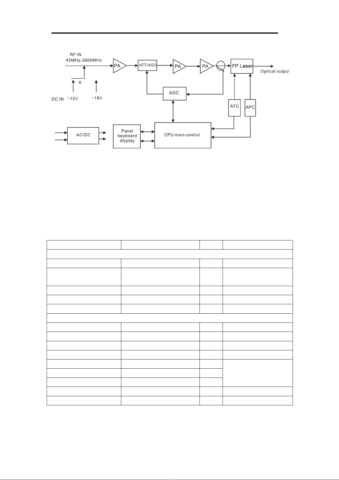
1.2 Product Description ..................................................................................... - 2 -
1.3 Product Applications .................................................................................... - 3 -
2. Technical Parameters ............................................................................................ - 3 -
3. Panel Interface and Menu System Description ..................................................... - 4 -
3.1 Front Panel ................................................................................................... - 4 -
3.1.1 Indicator Status Description .............................................................. - 4 -
3.2 Rear Panel .................................................................................................... - 5 -
3.3 Menu Operation ........................................................................................... - 5 -
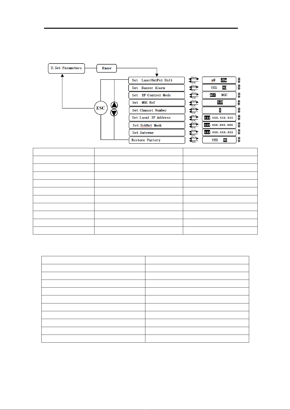
3.3.1 Main Menu ........................................................................................ - 5 -
3.3.2 Display Menu .................................................................................... - 6 -
3.3.3 Setup Menu ........................................................................................ - 7 -
3.3.4 Alarm Menu ....................................................................................... - 7 -
4. Installing the 20MM-LT06L Optical Transmitter ................................................. - 8 -
4.1 Receiving and Inspecting ............................................................................. - 8 -
4.2 Precautions ................................................................................................... - 8 -
4.3 Mounting the 20MM-LT06L ....................................................................... - 8 -
4.3.1 Mount the 20MM-LT06L in a cabinet ............................................... - 8 -
4.3.2 Connecting the RF Cables ................................................................. - 9 -
4.3.3 Connecting the Optical Fiber Cables ................................................. - 9 -
4.3.4Connecting the Ethernet Cable ........................................................... - 9 -
4.3.5 Connecting Power ............................................................................ - 10 -
5. Communication Setup ........................................................................................ - 10 -
5.1 RS232 Communication Interface Description ........................................... - 10 -
5.2 Set up the Hyper Terminal ......................................................................... - 10 -
5.3 Operating Parameter Configuration ........................................................... - 12 -
5.4 Remote Monitoring: SNMP ....................................................................... - 14 -
6. Maintenance and Troubleshooting ...................................................................... - 16 -
6.1 Cleaning Fiber Optic Connectors .............................................................. - 16 -
6.1.1 Cleaning Patch Cord or Pigtail Fiber Optical Connectors ............... - 16 -
6.2 Troubleshooting ......................................................................................... - 17 -
6.3 After-sales Service Description ................................................................. - 18 -
6.4 Disclaimer .................................................................................................. - 18 -

20MM-LT06L Optical Transmitter Operating Manual
- 2 -
1. Product Summary
1.1 About This Manual
This instruction manual is a complete guide to installing and operating the (1RU)
20MM-LT06L direct modulated optical transmitter. Please read the entire manual
before beginning installation.
This manual applies to 20MM-LT06L direct modulated optical transmitter.
• Chapter 1 gives general information about the 20MM-LT06L.
• Chapter 2 describes the technical parameters.
• Chapter 3 describes the panel interface and menu system.
• Chapter 4 tells you how to install the 20MM-LT06L.
• Chapter 5 describes the communication setting
• Chapter 6 describes maintenance and what to do in the event of problems.
1.2 Product Description
20MM-LT06L satellite optical transmitter adopts a high linearity cooling DFB
laser, direct modulated. Simultaneous transmission of 47-862MHz CATV signal and
950~2600MHz satellite direct TV signal in one optical fiber.
20MM-LT06L satellite optical transmitter can use ITU standard wavelengths and
be integrated with DWDM for Network upgrades and expansion. Its optical power
can be amplified by an EDFA or YEDFA to achieve large area FTTx. It is compatible
with FTTx PON technology to achieve FTTH and the multi-network integration of
CATV (Analogue, DVB-T,T2, DVB-C), Satellite Television (DVB-S/S2) and Internet.
20MM-LT06L is in 1RU 19” standard rack form, with a built in microprocessor
controlling the working parameters via keys and front panel LCD to provide status
display and fault diagnosis. Standard RJ45 communication interface, with SNMP
network management function. Built-in perfect laser APC and ATC control circuit to
ensure the long working life and high reliable of the laser.
SAT-IF adopts a high linearity IF driving amplifier circuit with AGC function to
ensure high-quality transmission of Analog TV, Digital TV (DVB-C, DVB-T/T2) and
Satellite TV in one optical fiber.

20MM-LT06L Optical Transmitter Operating Manual
- 3 -
Block Diagram:
1.3 Product Applications
• One optical fiber transmits CATV and Satellite band up to 2600MHz
• FTTx PON (EPON, GPON)
2. Technical Parameters
Performance
Index
Unit
Remark
Optical Characteristics
Laser Type
DFB
Specified by the user
Optical Wavelength
1310, 1550 or specified
by the user
nm
Specified by the user
Output Optical Power
2, 4, 6, 8, 10
mW
Specified by the user
Output Return Loss
50
dB
Optical Connector Type
SC/APC or FC/APC
Specified by the user
CATV RF Characteristics
Working Bandwidth
45-862
MHz
Input Range
75~85
dBµV
Input level
1
±1
dB
Input Return Loss
14
dB
C/N
≥51
dB
42CH CENELEC
80dBµV AGC
OMI=3.8%
C/CTB
≥63
dB
C/CSO
≥58
dB
Input Impedance
75
Ω
RF Connector
F type Male/Female
Specified by the user

20MM-LT06L Optical Transmitter Operating Manual
- 4 -
SAT-IF Characteristics
Working Bandwidth
950~2600
MHz
Input Range
68~83
dBµV
Input level
Flatness
±1
dB
Input Return Loss
10
dB
C/IM3
≥55
Note1
General Characteristics
Power Supply (AC)
110~265
V
Optional dual power
Consumption
20
mW
SNMP network
management interface
RJ45
Working Temperature
0~50
°C
Storage Temperature
-40~60
°C
Dimension (W)*(D)*(H)
1U 19 inch
483*395*44
mm
Note1: C/IM3 is defined as the ratio between the peak of carrier signal and triple beat
(IM3) by using a two-tone test (1.0GHz and 1.1GHz).
3. Panel Interface and Menu System Description
3.1 Front Panel
1
Power indicator
2
Run indicator
3
Laser working indicator
4
RF input indicator
5
LCD
6
ESC
7
Down
8
Up
9
Enter
10
Laser switching key
11
RF input test port
3.1.1 Indicators Status Description
Power indicator
Power on
LED green
Run indicator
Normal
LED green
Laser indicator
ON
LED green
RF input indicator
No input or exceed the
normal range
LED flash red
Normal
LED green

20MM-LT06L Optical Transmitter Operating Manual
- 5 -
3.2 Rear Panel
1
Fan outlet
2
RF signal input port
3
Voltage output switch
4
+18V indicator
5
+12V indicator
6
RS232 interface
7
LAN interface
8
Optical output interface
9
Power socket
10
Power socket
11
Ground stud
Note: When the voltage output is switched on the ‘-’ side, the +12V indicator is on
and the RF signal input port is supplied with +12VDC voltage output.
When the voltage output is switched on the ‘○’ side, the RF signal input port
has no voltage output.
When the voltage output is switched on the ‘=’ side, the +18V indicator is on
and the RF signal input port is supplied with +18VDC voltage output.
3.3 Menu Operation
3.3.1 Main Menu
Display parameters
Description
Boot display
1.Disp Parameters
Menu 1: Display parameters
2.Set Parameters
Menu 2: Set parameters
3.Alarm Status
Menu 3: Alarm status

20MM-LT06L Optical Transmitter Operating Manual
- 6 -
3.3.2 Display Menu
Display
parameters
Description
Display
parameters
Description
Laser Output
Output optical power
+24V
+24V monitor voltage
Laser Bias
Laser current
S/N
Serial number
Laser Temp
Laser temperature
BOX
Temperature
Box temperature
TEC Cooling
Cooling current
IP Address
IP address
RF Control
Mode
RF control mode
Sub Mask
Subnet mask
AGC Ref
AGC attenuation
Net Gateway
Gateway
+5V
+5V monitor voltage
MAC
Mack address
-5V
-5V monitor voltage
Software Ver
Software version number
+12V
+12V monitor voltage
+18V
+18V monitor voltage

20MM-LT06L Optical Transmitter Operating Manual
- 7 -
3.3.3 Setup Menu
Display parameters
Description
Remark
Set Laser Output Unit
Set optical power output unit
mW and dBm optional
Set Buzzer Alarm
Set buzzer alarm
YES is on, NO is off
Set RF Control Mode
Set RF control mode
AGC and MGC optional
Set MGC Ref
Set attenuation under MGC mode
Adjustable range 0~15dB
Set AGC Ref
Set attenuation under AGC mode
AGC control range -3~+3dB
Set Channel Number
Set channel number
Set Local IP Address
Set IP address
Set Subnet Mask
Set subnet mask
Set Gateway
Set gateway
Restore Factory
Restore factory settings
3.3.4 Alarm Menu
Display alarm content
Description
RF Alarm
RF alarm
Laser Temp
Laser temperature alarm
Laser Bias:
Laser current alarm
Output Alarm
Output alarm
Laser Tec
Laser cooling current alarm
+5V Alarm
+5V voltage alarm
-5V Alarm
-5V voltage alarm
+12V Alarm:
+12V voltage alarm
+18V Alarm:
+18V voltage alarm
+24V Alarm
+24V voltage alarm

20MM-LT06L Optical Transmitter Operating Manual
- 8 -
4. Installing the 20MM-LT06L Optical Transmitter
4.1 Receiving and Inspecting
As you unpack your unit, inspect the shipping container and equipment for damage.
Save the shipping material for future use. If the container or the equipment is
damaged, notify both the freight carrier and Matchmaster.
CAUTION: To protect yourself from potential injury and to protect the
equipment from further damage, do not perform any
operational tests if the equipment appears to be damaged.
4.2 Precautions
Heed the following precautions when working with the 20MM-LT06L.
Warning
Read the installation instructions before connecting the
system to the power source.
Warning
The power socket ends must be accessible at all times, as it
serves as the mains disconnection.
4.3 Mounting the 20MM-LT06L
4.3.1 Mount the 20MM-LT06L in a cabinet
To mount the 20MM-LT06L in a standard 19-inch equipment cabinet:
1. Place the unit in the cabinet.
2. Use four mounting screws to attach the mounting ears on the front panel to the
cabinet.
3. Reliably ground the equipment, the ground terminal is on the rear panel.
4. Visually inspect each key (button) on the front panel to ensure that it is not
trapped under the edge of its hole. If a key is trapped, tap the key to enable it to
move freely.

20MM-LT06L Optical Transmitter Operating Manual
- 9 -
4.3.2 Connecting the RF Cables
Verify the type of RF input F connector according to the ordering information, and
then connect with the matched RF cable.
4.3.3 Connecting the Optical Fiber Cables
20MM-LT06L has one output optical connector.
DANGER: The fiber carries invisible laser radiation. AVOID DIRECT
EXPOSURE TO BEAM. Never operate the unit with a
broken fiber or with a fiber connector disconnected.
1. Verify the optical fiber connector type is matched with 20MM-LT06L according
to the ordering information. (SC/APC)
2. Verify that the fiber cable connector has been cleaned properly. If the fiber cable
connector needs to be cleaned, follow the cleaning procedure outlined in
“Cleaning Patch Cord or Pigtail Fiber Optical Connectors”.
3. Verify that the 20MM-LT06L optical connector has not been exposed to any
contamination.
NOTE: Any contamination of the optical connector can significantly
degrade optical link performance. This degradation will most
likely manifest itself as poor signal-to-noise (SNR) performance.
4. Note the key characteristics of the mating connectors and align them accordingly.
4.3.4 Connecting the Ethernet Cable
You can connect the 20MM-LT06L to your TCP/IP network in order to monitor and
control the transmitter remotely. After you complete the installation procedures
described in this chapter, you can use a network management system (NMS) to
monitor and control the 20MM-LT06L.
To connect the 20MM-LT06L, you must use a shielded and grounded Category 5
Ethernet cable.
To connect the Ethernet cable:
1. Connect an Ethernet cable to the transmitter’s RJ-45 Ethernet port and to your
TCP/IP network. The Ethernet port is on the rear of the transmitter.
2. Verify that the green Link LED is illuminated, indicating that there is a
connection.

20MM-LT06L Optical Transmitter Operating Manual
- 10 -
4.3.5 Connecting Power
20MM-LT06L uses 110-265VAC power supply. Follow the power connection
procedure below.
It has two 110-265V power supplies that require input voltage from 110 to 265 VAC,
at 50 to 60Hz single phase. The AC power plug is located on the rear panel.
Connect the power; it takes about 60 seconds for all systems to operate.
5. Communication Setup
5.1 RS232 Communication Interface Description
Adopt DB9 standard connector, the pin definitions as follow:
1: No Connect
2: TX
3: RX
4: No Connect
5: GND
6: No Connect
7: No Connect
8: No Connect
9: No Connect
The serial communication uses the standard NRZ form, 1 starts bit, 8 data bits, 1
stop bit and the baud rate is 38400.
5.2 Set up the Hyper Terminal
If you have not setup the Hyper Terminal in your Windows system, follow the steps:
Click “start menu àprogramà accessoryàcommunicationàHyper Terminal”:
This results in the following screen:

20MM-LT06L Optical Transmitter Operating Manual
- 11 -
Then you input your connection name, such as “SNMP38400”,and choose the serial
port to connect with your equipment. As follows:
Press the “OK” button shows the configuration page of serial port. As follows:
Change the serial port configuration to 38400-baud rate, 8 data bits, no parity bit, 1
stop bit, no data flow control, press the “OK” button, and you have set up the
Windows serial port Hyper Terminal.

20MM-LT06L Optical Transmitter Operating Manual
- 12 -
You can click “fileàsave” menu to save this configuration of Hyper Terminal for
later use.
5.3 Operating Parameter Configuration
Under the condition of power off, use the serial port lines to connect the RS232 port
with the computer port. Open the Windows Hyper Terminal which you have set up.
Then turn on the power, you will see the page as follows. Enter the password to enter
the configuration interface.
Enter the password, display the following screen:
You can input your command in this page, and then configure the operating parameter
of the application program.

20MM-LT06L Optical Transmitter Operating Manual
- 13 -
System supports the following commands:
help
ethcfg
settrap
community
Restore
setsn
setpswd
entplogo
Exit
Specific using as follows:
help
This command shows current application program version, program name and the
internal commands list of the system as follows:
You can also use the “help” command to show help information of other commands,
such as “help ethcfg”,ethcfg’s help information appears as follows:
List internal commands of the system;
Configure the Ethernet operating parameters;
Configure the aim host IP address of the SNMP Trap;
Configure the SNMP group name;
Restore the factory default values;
Set serial number;
Set login password;
Set company logo and equipment model;
Logout;

20MM-LT06L Optical Transmitter Operating Manual
- 14 -
ethcfg
This command configures the Ethernet parameters, including IP address, subnet mask
and gateway. You can refer to the help information for its use.
settrap
This command shows or modifies the aim host IP address list of the SNMP Trap,
IP address of 0.0.0.0 and 255.255.255.255 don’t exist. SNMP Trap does not send to
these two addresses.
community
This command configures the read-only group name and read-write group name.
“Group name” is the concept of SNMP agreement like the password. Use the
command “community ro” to configure the read-only, and “community rw” for the
read-write. For example, input “community rw public”, “public” is the read-write
group name. The group name for read-only and read-write are both “public” as the
equipment default setting from factory.
setpswd
This command is used to modify login password.
entplogo
This command is used to set company logo and equipment model.
Exit
This command is used to logout.
5.4 Remote Monitoring: SNMP
LAN communication interface
Adopt RJ45 standard connector, the pin definitions as follow:

20MM-LT06L Optical Transmitter Operating Manual
- 15 -
1: TX+
2: TX-
3: RX+
4: No Connect
5: No Connect
6: RX-
7: No Connect
8: No Connect
A: Green indicator flashing means that the LAN port is sending data.
B: Yellow indicator means that the network connection is normal.
SNMP basic background
Simple Network Management Protocol (SNMP) is an application layer protocol.
It makes the management information between network devices exchange easier. It is
part of the TCP / IP protocol group. SNMP enables the end-users to manage network
performance, find and solve network problems, and arrange for future network
upgrades.
Management Information Base (MIB) is the organized hierarchical information
set. Use SNMP to visit these MIB. They are composed of manageable information
and identified by the object identifier.
SNMP
Transmitter configuration of network communication
When the transmitter initial work, the IP address and gateway are in the default
state, you need to configure them. The configuration of initial state can be achieved
through the RS-232 interface or the front panel keys. Other configurations see our
<Network Management Instructions>.

20MM-LT06L Optical Transmitter Operating Manual
- 16 -
6. Maintenance and Troubleshooting
6.1 Cleaning Fiber Optic Connectors
DANGER: The fiber optic connector carries invisible laser radiation
while working, so should avoid charged operation.
Dirty optical connectors are the leading source of poor performance in a
broadband optical fiber network. Dirty optical connectors lead to optical signal
loss and reflections, which in turn can seriously degrade signal-to-noise (SNR)
performance and, in some cases, distortion performance. We recommend that
you clean all mating fiber connectors before connecting them to an optical
transmitter.
In addition, if you suspect that the optical connector of 20MM-LT06L may have
been exposed to contamination (by a dirty fiber cable connector, for example),
you should properly clean the optical connector before connecting the optical
fiber.
CAUTION: Improper cleaning of an optical connector can do more
harm than good. Never spray a clean-air product onto the
surface of an optical connector. Spraying air onto an
optical connector can cause condensation on the connector
surface, leaving water spots and trapping dust. Failing to
wipe a connector on dry lens paper immediately after
wiping on paper wet with isopropyl alcohol can also lead
to condensation on the connector. Using low-grade
cleaning paper or other cloth to wipe an optical connector
can leave microscopic fibers on the optical connector
Surface.
6.1.1 Cleaning Patch Cord or Pigtail Fiber Optical Connectors
To clean optical connectors, we recommend using a fiber optic connector cleaning
cartridge (such as NTT Cletop). If a cleaning cartridge is not available, follow these
steps.
To clean the optical connector of a patch cord or pigtail:
1. Fold a piece of unused dry lens cleaning paper twice, for a four-ply thickness.
2. Use a drop of high-grade isopropyl alcohol to wet part of the paper.
3. Lay the connector on the lens cleaning paper with the tip touching the paper.
4. In one continuous motion, pull the connector from the wet part of the paper to the
dry part.

20MM-LT06L Optical Transmitter Operating Manual
- 17 -
6.2 Troubleshooting
Should a problem occur, see if the symptoms are listed in Table 6-1.
Table 6-1: Troubleshooting Solutions
Indicator
status
Alarm menu
content
Fault phenomenon
Solution
Run
indicator
green flash
Normal
Normal
Operation Normal
RF indicator
red flash
RF IN Status
LOW (HIGH)
RF input is low
(high)
Verify the optical transmitter
is operating within the proper
input level threshold range
(-25~-5dBm).
If that does not correct the
problem, contact Customer
Service.
Laser
indicator
red flash
Laser Bias
HIGH
The laser is off
Contact Customer Service.
Laser TEC
HIGH
The laser is off
Verify that the unit is
operating within the proper
temperature range (0~+50°C).
Verify that nothing is
obstructing airflow through
the openings in the front and
back of the unit.
Recall factory settings by
pressing the key on the front
panel (see Section 3).
If that does not correct the
problem, contact Customer
Service.
Output Power
Status HIGH
(LOW)
The laser is off
Reboot the equipment. If that
does not correct the problem,
contact Customer Service.
None
None
The optical output
power is lower than
the nominal value
Check the fiber drawer.
Follow the connector cleaning
procedure (see Section 6.1).
If that does not correct the
problem, contact Customer
Service.

20MM-LT06L Optical Transmitter Operating Manual
- 18 -
6.3 After-sales Service Description
1. If the equipment fault is resulted from the users’ improperly operating or
unavoidable environment reasons, charges will apply for replacement or repair.
2. Any site maintenance of the faulted equipment must be operated by professional
technicians to avoid further damage.
6.4 Disclaimer
We reserve the right to change any products described herein at any time, and without
prior notice. We assume no responsibility or liability arising from the use of the
products described herein, except as expressly agreed to in writing by us. The use and
purchase of this product does not convey a license under any patent rights, copyrights,
trademark rights, or any intellectual property rights of us. Nothing hereunder
constitutes a representation or warranty that using any products in the manner
described herein will not infringe any patents of third parties.
Table of contents
Other Matchmaster Transmitter manuals