2000
B
D
DIMENSIONS
IMPORTANT
Dimensions are approximate
Before disposing of carton and/or commencing assembly, please check all the parts to ascertain that none are missing and they are all
undamaged. No claim for missing/damaged parts will be accepted once the packing carton has been disposed of and/or assembly has
commenced.
In case of query contact your Stockist with details of model number and details of serial number.
PREPARATION IMPORTANT
1. Please read complete installation instructions before fitting for enclosure and tray (if fitting).
2. We recommend the use of safety glasses and non slip gloves when handling the glass panels.
3. Ensure that the product can be fixed to a solid masonry wall or suitable timber stud work grade C16/C24 in the area behind the
wall frames.
4. Shower trays or tiled floors must be absolutely level where enclosures are fitted
5. If fitting a tray we recommend a drainage test is carried out before the tray is tiled in position.
6. The assembly should be installed onto a waterproof wall covering and installed after the tray and wall coverings are in place.
Trays with tiling lips should be let into the wall with the tiling lip flush with the wall to allow the tiling to overlap the tiling lip.
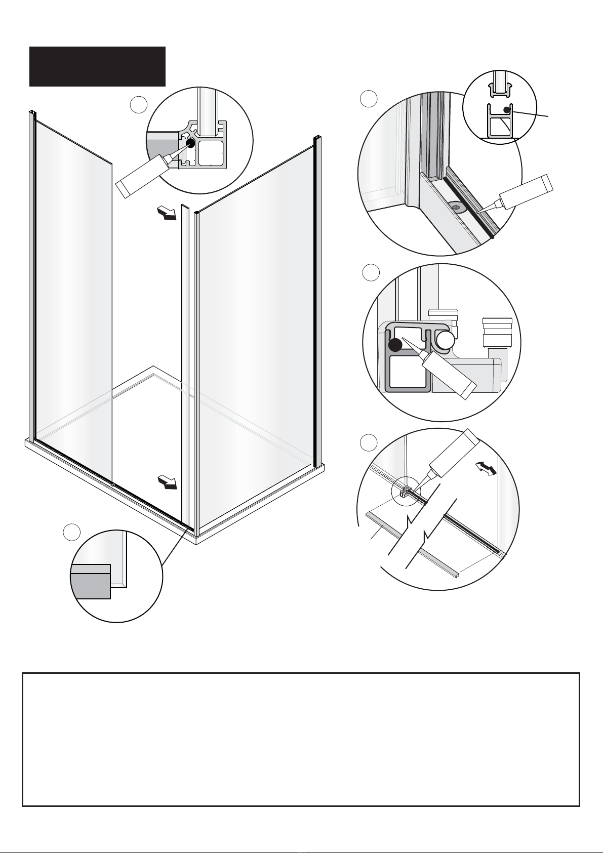
7. Seal between tray and tiles. Remove any excess sealant from the area/joint between the tray and the tiles where the wall mount is
to be fitted. This will ensure the wall mount fits correctly to the wall and tray/or tiled floor.
CAUTION: TEMPERED GLASS CANNOT BE CUT, POLISHED METAL AND CHROME CAN BE SCRATCHED. CAREFULLY
REMOVE ASSEMBLY FROM CARTON, DO NOT PLACE GLASS ON HARD FLOOR OR EXPOSE EDGES TO IMPACT. DO NOT
CUT TOP TRACK IN ANY CIRCUMSTANCES.
TOOLS REQUIRED
Masonry Drill bit 6mm, Tape Measure, Screw Drivers, Safety Glasses, Electric Drill, Level,
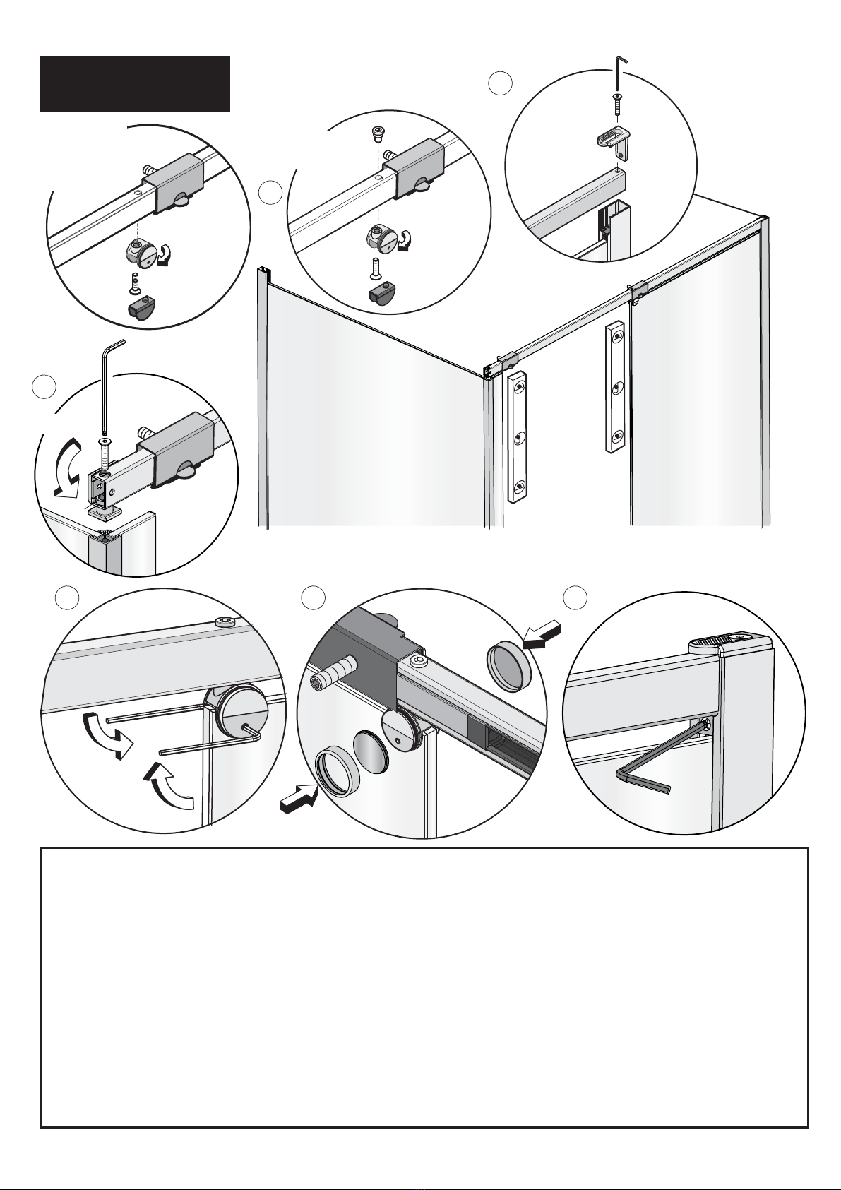
Pencil, Adjustable Spanners, Non Slip Gloves, Glass suction lifter, 2mm & 4mm Allen Keys
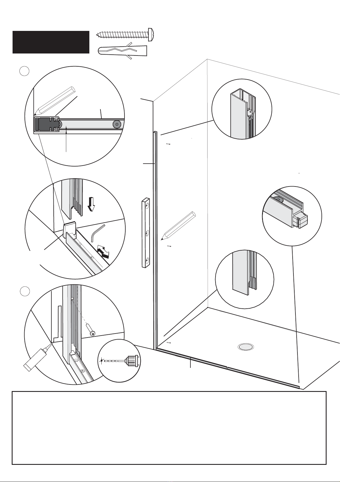
MATKI ONE CORNER SLIDER
E - SIDE PANEL
C- DOOR
OPENING
Side Panel E
MOSCSP760 732-752
MOSCSP800 772-792
MOSCSP900 872-892
MOSCSP1000 972-992
Model A B C D
MOSC1000 978-998 470-490 400 65
MOSC1100 1078-1098 490-510 440 65
MOSC1200 1178-1198 570-590 450 65
MOSC1400 1378-1398 680-700 550 65
MOSC1500 1478-1498 780-800 550 65
MOSC1600 1578-1598 780-800 650 65
MOSC1700 1678-1698 880-900 650 65
A - OVERALL WIDTH
2020 -
TOP OF DOOR