Matrix eBLOCKS PICmicro EB006V9 User manual

www.matrixtsl.com
PICmicro® MCU multiprogrammer
EB006V9

2Copyright © 2014 Matrix Technology Solutions Ltd
Contents
About this document 3
General information 4
Board layout 5
Circuit description 6
Protective cover 7
PICmicro microcontroller pin out details 8
Bus connections 9
Circuit diagram 11

3Copyright © 2014 Matrix Technology Solutions Ltd
About this document
This document concerns the EB006V9 E-blocks
PICmicro multiprogrammer board (version 9).
1. Trademarks and copyright
PIC and PICmicro are registered trademarks of Arizona
Microchip Inc. E-blocks is a trademark of Matrix
Technology Solutions Ltd.
2. Disclaimer
The information provided within this document is
correct at the time of going to press. Matrix TSL reserves
the right to change specications from TSL to time.
3. Testing this product
It is advisable to test the product upon receiving it to
ensure it works correctly. Matrix provides test procedures
• How to get started with E-blocks - if you are new to
E-blocks and wish to learn how to use them from the
beginning there are resources available to help.
• Relevant software and hardware that allow you to use
your E-blocks product better.
• Example les and programs.
• Ways to get technical support for your product, either
via the forums or by contacting us directly.
for all E-blocks, which can be found in the Support
section of the website.
4. Product support
If you require support for this product then please
visit the Matrix website, which contains many learning
resources for the E-blocks series. On our website you will
nd:
General information
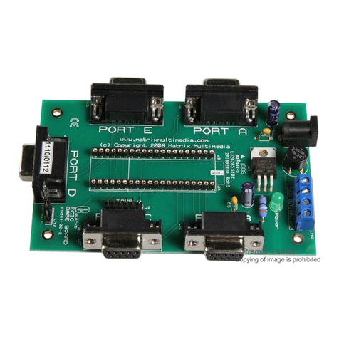
The EB006 V9 PICmicro microcontroller programmer
connects to your PC via USB to provide you with a low
cost and exible PICmicro microcontroller programmer.
This board can be used with conventional microcontroller
programs that generate hex code for the PIC family:
MPLAB, C compilers, BASIC compilers etc. The EB006
V9 has many features that are optimised for use with
Flowcode version 6 including Ghost technology.
The board will program most 8, 14, 18, 20, 28 and 40 pin
ash PICmicro microcontroller devices using the free
‘mLoader’ programming software provided. mLoader
can be downloaded from the Matrix web site.
The board also provides ‘clean’ access to all Input/Output
lines on the relevant PICmicro microcontroller device.
These are presented on 9 way D-type connectors: 8 bits
and earth. A range of additional E-blocks boards can
plug into these D-type connectors to provide a rapid
prototyping system for learning and development.
More information on Ghost technology can be found on
our website at www.matrixtsl.com/ghost.
1. Features
• E-blocks compatible
• Low cost
• Used as a programmer and as a development board
• Programs a wide range of PICmicro MCU devices
• Full suite of programming software available
• Ghost technology included
• Removable crystal oscillator source
• 5 I/O ports
• In-Circuit Debugging via PICkit2 connector
• In-Circuit Debug with Flowcode 6
• In-Circuit Test with Flowcode 6
• Charge pump capability to allow high voltage
programming from USB supply
• 2mm power connector sockets
• Powerful 16bit host chip with Ghost technology
operating system included
• All pins on target device monitored by host
microcontroller
• On-board SRAM memory for data storage
• LEDs for Power, In-Circuit -Debug, In-Circuit -Test,
and Program
• Lower operating voltage (9V)

Copyright © 2014 Matrix Technology Solutions Ltd4
General information
2. Block schematic
3. Support devices
Currently mLoader and the EB006V9 support the
following PICmicro devices:
12F Devices
PIC12F609, PIC12F615, PIC12F617, PIC12F629, PIC12F635, PIC12F675,
PIC12F683, PIC12F752
16F Devices
PIC16F1516, PIC16F1517, PIC16F1518, PIC16F1519, PIC16F1526,
PIC16F1526, PIC16F1782, PIC16F1783, PIC16F1823, PIC16F1824,
PIC16F1825, PIC16F1826, PIC16F1827, PIC16F1828, PIC16F1829,
PIC16F1847, PIC16F1933, PIC16F1934, PIC16F1936, PIC16F1937,
PIC16F1938, PIC16F1939, PIC16F1946, PIC16F1947, PIC16F610,
PIC16F616, PIC16F627A, PIC16F627, PIC16F628A, PIC16F628,
PIC16F630, PIC16F631, PIC16F636, PIC16F639, PIC16F648A,
PIC16F676, PIC16F677, PIC16F684, PIC16F685, PIC16F687, PIC16F688,
PIC16F689, PIC16F690, PIC16F72, PIC16F720, PIC16F721, PIC16F737,
PIC16F73, PIC16F747, PIC16F74, PIC16F767, PIC16F76, PIC16F777,
PIC16F785, PIC16F77, PIC16F818, PIC16F819, PIC16F84A,, PIC16F870,
PIC16F871, PIC16F872, PIC16F873A, PIC16F873, PIC16F874A,
PIC16F874, PIC16F876A, PIC16F876, PIC16F877A, PIC16F877,
PIC16F87, PIC16F88, PIC16F882, PIC16F883, PIC16F884, PIC16F886,
PIC16F887, PIC16F913, PIC16F914, PIC16F916, PIC16F917, PIC16F946
18F Devices
PIC18F242, PIC18F248, PIC18F252, PIC18F258, PIC18F442, PIC18F448,
PIC18F452, PIC18F458, PIC18F1220, PIC18F1230, PIC18F1231,
PIC18F1320, PIC18F1330, PIC18F1331, PIC18F13K50, PIC18F14K50,
PIC18F2220, PIC18F2221, PIC18F2320, PIC18F2321, PIC18F2331,
PIC18F23K20, PIC18F23K22, PIC18F2410, PIC18F2420, PIC18F2423,
PIC18F2431, PIC18F2439, PIC18F2450, PIC18F2455, PIC18F2458,
PIC18F2480, PIC18F24K20, PIC18F24K22, PIC18F24K50, PIC18F2510,
PIC18F2515, PIC18F2520, PIC18F2523, PIC18F2525, PIC18F2539,
PIC18F2550, PIC18F2553, PIC18F2580, PIC18F2585, PIC18F25K20,
PIC18F25K22, PIC18F2610, PIC18F2620, PIC18F2680, PIC18F2682,
PIC18F2685, PIC18F4220, PIC18F4221, PIC18F4320, PIC18F4321,
PIC18F4331, PIC18F43K20, PIC18F43K22, PIC18F4410, PIC18F4420,
PIC18F4423, PIC18F4431, PIC18F4439, PIC18F4450, PIC18F4455,
PIC18F4458, PIC18F4480, PIC18F4510, PIC18F4515, PIC18F4520,
PIC18F4523, PIC18F4525, PIC18F4539, PIC18F4550, PIC18F4553,
PIC18F4580, PIC18F4585, PIC18F4586, PIC18F45K20, PIC18F45K22,
PPIC18F4610, PIC18F4620, PIC18F4680, PIC18F4681, PIC18F4682,
PIC18F4685, PIC18F46K20, PIC18F46K22

5Copyright © 2014 Matrix Technology Solutions Ltd
Board layout
1
2
3
19
4
24
16
21
5
6
20
14
12
13
22
23
15
11
10
9
87
25
17
1. Power connector - either polarity 7.5 – 9V
2. USB connector
3. Reset switch
4. Port E I/O
5. Port A I/O
6. Port B I/O
7. Port C I/O
8. Port D I/O
9. PICkit ICSP Header
10. Removable crystal / oscillator pin assignment jumper
11. 2mm sockets for supplying power to downstream E-block
boards
12. Analogue switch to allow programming and debug pins
to be connected / disconnected from circuit
13. Power screw terminals
14. USB/ICSP programming selector
15. USB/PSU power selector
16. 5V voltage regulator
17. 3V3/5V VDD voltage selector
18. Bridge rectier
19. 3V3 voltage regulator
20. SRAM storage IC
21. Status LEDs, Power, ICD, Test, Program
22. Powerful host microcontroller
23. Charge pump circuitry
24. Turned pin DIL socket for 18 pin PICmicro devices
25. Turned pin DIL socket for 28 and 40 pin PICmicro devices /
40 pin 16F1937 Target Microcontroller (supplied)
26. Turned pin DIL socket for 8, 14, 20 pin PICmicro devices
18
26

6Copyright © 2014 Matrix Technology Solutions Ltd
Circuit description
The multiprogrammer solution is made up of two
parts: a circuit board that allows various slave PICmicro
devices to be programmed, and the Windows based
programming utility ‘mLoader’.
1. Power supply
The board is normally operated from a regulated DC
supply of 7.5 - 9V or from a USB supply. This allows full
operation including programming. The board can be
operated solely from the USB cable provided. However
care must be taken, as there is only limited power that
can be taken from a computer’s USB port.
The jumper link system, J11, allows the user to decide
on the source of the power supply. If using a regulated
7.5V power supply the jumper should be positioned to
the right hand side of the jumper system labeled‘PSU’. If
using USB power place the jumper on the left hand side
of the jumper system. LED D6 indicates that power is
correctly supplied to the board.
Please note that both USB and the PSU cables should
be removed for the Multiprogammer board BEFORE
changing the position of this jumper.
Remember that other E-blocks will have to receive their
voltage by placing a connecting wire from the“+V”screw
terminal of the Multiprogrammer to the “+V” screw
terminal of each E-Block that requires a voltage.
WARNING: Take extra care when wiring in a
power supply 12V may cause the board to run
hot.
2. Programming circuit
The Multiprogrammer connects to a personal computer
via the USB socket. Any USB socket on the PC can be
used. The host microcontroller is used to communicate
between the USB bus and the Multiprogrammer
circuitry. The host is connected to a network of analogue
switches formed by U4 and a charge pump circuit which
is used to multiply the operating voltage up to the 9-12V
programming voltage. This circuitry routes 0V, VDD and
VPP to appropriate pins on the slave PICmicro devices as
and when necessary.
3. DIL sockets and I/O ports
The slave PICmicro DIL sockets are wired in parallel (see
table of connections below) and the ports are fed out to
5 D-type sockets grouped in ports. These signals are also
available on a 40-way header (J5) for expansion purposes.
Other important signals can be accessed via the other
expansion header J24 (see table of connections below).
Port E has only 3 connections, which reects the pin outs
of the various PICmicro devices themselves. When using
an 8-pin or 14-pin device it should be placed in the upper
pins of the 20-pin DIL socket as marked on the board.
Please refer to device datasheets for availability of port
outputs on each device.
NOTE: RA4 on some PICmicro devices has an open
collector output. This means that you will most likely
need a pull up resistor to be able to drive an LED etc.
Please see the datasheet on the device you are using
for further details. (Does not apply to 16F1937 device
supplied with the board).
WARNING: Only t one PICmicro device at a time.
Inserting more then one PICmicro device will
cause programming to fail and may even cause
damage to the board or the PICmicros.
4. Reset push button
PB1 provides a reset by pulling the MCLR pin low. Note
that the programming chip will reset the slave PICmicro
as part of the send routine so that you do not need to
press this switch each time you send your program to
the board. If you are using a device with internal MCLR
functionality then you will have to ensure that the chip
is congured with an external MCLR to allow the reset
operation to work. Devices using the internal MCLR
conguration setting will be able to use the reset switch
as a digital input.
5. Frequency selection
By default the board is tted with a 19.6608MHz crystal.
The crystal ts into a small socket, which allows the
crystal to be easily changed. For older Matrix TSL courses
a 3.2768MHz crystal is recommended. These frequencies
are chosen as they divide down by PICmicro prescalers
to give suitable frequencies for clock systems and for
facilitating serial communication using standard baud
rates.
The Jumper link system J18, J19 allows PICmicro devices
with internal oscillators to route the signals from the
oscillator pins through to Port A pins 6 and 7. This allows
the devices with internal oscillators to use all 8-bits of
the Port A for I/O operation.

7Copyright © 2014 Matrix Technology Solutions Ltd
6. In-Circuit Debugging
The Multiprogrammer board has an in-circuit debugging
(ICD) connection between the USB peripheral device
and the target microcontroller. This allows the Flowcode
software to start, stop, step and inspect an active
program, synchronized both in hardware and Flowcode
6 software. As well as the standard ICD operation,
Flowcode is capable of reading back real time variable
values from the target device.
To use the Microchip PICkit2 ICSP interface, remove
the power supply and the USB cable from the
Multiprogrammer. Then place the 3-way jumper link
associated with J12-14 to the left hand side of the 3 x
3 header pins, labeled ‘ICSP’. Then simply connect the
PICkit into the Multiprogrammer via header J20.
7. In-Circuit Test
The Multiprogrammer board has an in-circuit test (ICT)
connection between the USB peripheral device and all
of the target microcontroller’s I/O pins. This allows the
Flowcode 6 software to monitor all of the signals on the
board in either analogue or digital modes.
The in circuit test feature can be combined with packet
decoding to allow data and control busses to be explored
and debugged
8. Low voltage programming
Many PICmicros have a low voltage programming mode
where it is possible to program the device without the
need for a 12V supply line or charge pump. The diculty
here is that dierent families of PICmicro devices use
dierent pins as the Low Voltage programming pin. B3 is
predominantly used for this function but B4 and B5 are
also used on some devices. For this reason the version
9 EB006 does not support low voltage programming
modes so care must be taken when generating the chip
conguration to disable the low voltage programming
functionality. If the low voltage programming
conguration is left enabled then you will not be able to
use the LVP pin as an I/O pin in your application.
Protective cover
Most of the boards in the E-blocks range can be tted
with a plastic cover as an optional extra. These covers
are there to protect your E-blocks board therefore
extending the life of the board. The covers also prevent
the removal of external components while still allowing
for the adjustment of applicable parts on the board.
12mm M3 spacers, anti-slip M3 nuts and 25mm M3 bolts
can be used to attached the cover to the board. These
are not included but can be bought separately
from our website.
The order code for the EB006
PICmicro® MCU microcontroller
cover is EB706.

8Copyright © 2014 Matrix Technology Solutions Ltd
PICmicro microcontroller pin out details
Broadly speaking the ranges of PICmicro devices are
designed to be upwards compatible: the pin functions
on an 18-pin device are available on a 28-pin device and
a 40-pin device. This can be seen from the following
excerpt from the Microchip product selector card. The
following diagram shows the pin out of the various
PICmicro devices:
RA1/AN1RA2/AN2/Vrefout 1 18
RA0/AN0RA3/AN3/CMP1/Vren 2 17
OSC1/CLKIN/RA7RA4/T0CKI/CMP2 3 16
OSC2/CLKOUT/RA6Vpp/RA5/THV/MCLR 4 15
VddVss 5 14
RB7/T1OSIRBO/INT 6 13
RB6/T1OSO/T1CKIRB1/RX/DT 7 12
RB5RB2/TX/CK 8 11
RB4/PGMRB3/CCP1 9 10
18-pin PICmicro
VssVdd 1 8
GP0/AN0GP5/OSC1/CLKIN 2 7
GP1/AN1/VrefGP4/OSC2/AN3/CLKOUT 3 6
GP2/T0CKI/AN2/INTVpp/GP3/MCLR 4 5
8-pin PICmicro
Note that GP0 maps to RB7
GP1 maps to RB6
GP2/AN2 maps to RA0/AN0
VssVdd 1 14
RA0/CIN+/ICSPDATRA5/T1CKI/OSC1/CLKIN 2 13
RA1/CIN-/ICSPCLKRA4/TIG/OSC2/CKLOUT 3 12
RA2/COUT/T0CKI/INTRA3/MCLR/Vpp 4 11
Rc0Rc5 5 10
Rc1Rc4 6 9
Rc2Rc3 7 8
14-pin PICmicro
VssVdd 1 20
RA0/D+/PGDRA5/OSC1/CLKIN 2 19
RA1/D-/PGCRA4/AN3/OSC2/CLKOUT 3 18
VUSBRA3/MCLR/Vpp 4 17
RC0/AN4/INTO/VREF+RC5/CCP1/P1A 5 16
RC1/AN5/INT1/VREF-RC4/P1B 6 15
RC2/AN6/INT2RC3/AN7/P1C/PGM 7 14
RB4/AN10/SDI/SDARC6/AN8/T1OSCO 8 13
RB5/AN11/RX/DTRC7/AN9/SDO/T1OSCO 9 12
20-pin PICmicro
RB6/SCK/SCLRB7/TX/CK 10 11
RB7/PGO/KB13MCLR 1 40
RB6/PGC/KB12RA0/AN0 2 39
RB5/KBI1RA1/AN1 3 38
RB4/KBI0RA2/AN2/Vrl/Vref- 4 37
RB3/PGM/CCP2/CANRXRA3/AN3/Vrh/Vref+ 5 36
RB2/INT2/CANTXRA4/T0CKI 6 35
RB1/INT1RA5/AN4/SS/Lvdin 7 34
RB0/INT0RE0/AN5/RD 8 33
VddRE1/AN6/WR 9 32
40-pin PICmicro
VssRE3/AN7/CS 10 31
RD7/PSP7/PDAvdd 11 30
RD6/PSP6/PCAvss 12 29
RD5/PSP5/PBOSC1/CLKI 13 28
RD4/PSP4/ECC/PAOSC2/CLKO/RA6 14 27
RC7/RX/DTRC0/T1OSO/T1CKI 15 26
RC6/TX/CKRC1/T1OSVCCP2 16 25
RC5/SKO/D+RC2/CCP1 17 24
RC4/SDI/SDA/D-RC3/SCK/SCL 18 23
RD3/PSP3/C2INRD0/PSP0/C1IN+ 19 22
RD2/PSP2/C2IN+RD1/PSP1/C1IN- 20 21
RB7/PGOVpp/MCLR 1 28
RB6/PGCRA0/AN0 2 27
RB5RA1/AN1 3 26
RB4RA2/AN2/Vrl/Vref- 4 25
RB3/PGM/CCP2RA3/AN3/Vrh/Vref+ 5 24
RB2/INT2RA4/T0CKI 6 23
RB1/INT1RA5/AN4/SS/Avdd/Lvdin 7 22
RB0/INTVss 8 21
VddOSC1/CLKI 9 20
28-pin PICmicro
VssOSC2/CLKO/T1CKI 10 19
RC7/RX/DTRC0/T1OSO/CCP2I 11 18
RC6/TX/CKRC1/T1OS/CCP2I 12 17
RC5/SDO/D+RC2/CCP1 13 16
RC4/SKI/SDA/D-RC3/SKC/SCL 14 15

9Copyright © 2014 Matrix Technology Solutions Ltd
Bus connections
1. Expansion bus
The pin connections on the expansion bus exactly mirror
the pin numbering on the 40-pin DIL socket. Note that
the pin numbering on the IDC socket is slightly dierent
to that on a DIL socket which results in the seemingly
odd arrangement of pins on the IDC pin chart.
PICmicro pinout
Bus name 18 Pin 8 Pin 14 Pin 20 Pin 28 Pin 40 Pin
Vpp/MCLR 4 4 4 4 1 1
Vdd 14 1 1 1 20 11 & 32
Vss 5 8 77 20 8 & 19 12 &31
OCS1 16 2 2 2 9 13
OCS2 15 3 3 3 10 14
RA0/AN0 17 19 2 2
RA1/AN1 18 18 3 3
RA2/AN2 1 4 4
RA3/AN3 2 4 5 5
RA4 3 3 6 6
RA5/AN4 4 2 7 7
RB0 6 21 33
RB1 7 22 34
RB2 8 5* 11* 23 35
RB3 9 24 36
RB4 10 13 25 37
RB5 11 12 26 38
RB6 12 6* 12* 11 27 39
RB7 13 7* 13* 10 28 40
RC0 10 16 11 15
RC1 9 15 12 16
RC2 8 14 13 17
RC3 7 7 14 18
RC4 6 6 15 23
RC5 5 5 16 24
RC6 8 17 25
RC7 9 18 26
RD0 19
RD1 20
RD2 21
RD3 22
RD4 27
RD5 28
RD6 29
RD7 30
RE0/AN5 8
RE1/AN6 9
RE2/AN7 10
For the 18, 28 and 40 pin devices the buses on devices
are largely upwards compatible - pin connections on an
18-pin device appear on a 28-pin device and a 40-pin
device, and pins on a 28-pin device appear on a 40-pin
device. This allows the 18, 28 and 40 pin DIL sockets to
be connected in parallel with the PICmicro bus structure
intact.
* This parallel connection is not possible with 8, 14 and
20 pin devices due to programming requirements which
means that there are anomalies with the pin connections
for the 8, 14 and 20 pin devices as follows:
Multiprogrammer port
line
Connection pin on 20
pin device
20 pin port line
RB2 5 RA2
RB6 6 RA1
RB7 7 RA0
Multiprogrammer port
line
Connection pin on 14
pin device
14 pin port line
RB2 5 RA2
RB6 6 RA1
RB7 7 RA0
Multiprogrammer port
line
Connection pin on 8
pin device
8 pin port line
RB2 1 RA2
RB6 12 RA1
RB7 13 RA0

10 Copyright © 2014 Matrix Technology Solutions Ltd
Bus name 40 pin J5 IDC connec-
tor
J24 IDC con-
nector
Vpp/MCLR 1 1 2
VCCchip 11& 32 18 & 21 21,22
GND 12 & 31 20 & 23 5
OCS1 13 25 26, 25
OCS2 14 27 28, 27
RA0/AN0 2 3 4
RA1/AN1 3 5 6
RA2 4 7 8
RA3/AN3 5 9 10
RA4/AN4 6 11 12
RA5 7 13 14
RB0 33 16
RB1 34 14
RB2 35 12
RB3 36 10 35
RB4 37 8
RB5 38 6
RB6 39 4 37
RB7 40 2 39
RC0 15 29 30
RC1 16 31 32
RC2 17 33 34
RC3 18 35 36
RC4 23 36
RC5 24 34
RC6 25 32
RC7 26 30
RD0 19 37 38
RD1 20 39 40
RD2 21 40
RD3 22 38
RD4 27 28
RD5 28 26
RD6 29 24
RD7 30 22
RE0/AN5 8 15 16
RE1/AN6 9 17 18
RE2/AN7 10 19 20
2. Connections on the IDC expansion connectors
Note: J5 is set to copy the 40-way DIL socket

11 Copyright © 2014 Matrix Technology Solutions Ltd
Circuit diagram

12 Copyright © 2014 Matrix Technology Solutions Ltd
Circuit diagram

Matrix Technology Solutions Ltd.
The Factory
33 Gibbet Street
Halifax, HX1 5BA, UK
t: +44 (0)1422 252380
www.matrixtsl.com
EB006-30-9
This manual suits for next models
1
Table of contents
Other Matrix Microcontroller manuals
Popular Microcontroller manuals by other brands

Silicon Laboratories
Silicon Laboratories C8051F31 Series user guide

Lattice
Lattice Himax HM01B0 UPduino Shield quick start

Microchip Technology
Microchip Technology ATWINC3400 user guide

Novatek
Novatek NT6862-5 Series manual

SmartNanotubes
SmartNanotubes Smell INSPECTOR Technical manual

Cypress Semiconductor
Cypress Semiconductor CYUSBS232 quick start guide