Matrot M24D Hellios User manual

Self-propelled Sprayer
User Guide V1.0
(Original user guide)
M24D Hellios

2 2011
User notice
M24D Hellios V 1.0

2011 3
User notice
M24D Hellios
V 1.0
Foreword
We warmly thank you for having chosen a MATROT M24D Hellios self-propelled machine and we are delighted
that you have decided to trust us for your spraying operations.
We request that you read this instruction manual and the maintenance log carefully. These two documents contain
all the information you need to use, adjust and maintain your self-propelled machine.
Scope
This device is reserved for professional use and has been exclusively designed for the spraying of phytosanitary
products (fungicides, herbicides and insecticides) and nitrogenous liquid fertiliser in fields. It must only be used for
this purpose.
General safety instructions
The MATROT M24D Hellios self-propelled machine must be used by personnel trained in
handling and use, and in the use of the treatments or fertilisers used with this equipment.
The MATROT M24D Hellios self-propelled machine must be used by personnel
trained in handling and use, and in the use of the treatments or fertilisers used with
this equipment. The sprayer must be cleaned in-depth prior to any maintenance
operation on the self-propelled machine. Maintenance and repair operations must
be carried out by an approved MATROT ÉQUIPEMENTS dealer.
Before using the equipment, the operator must read, understand and
integrate all of the instructions and danger warnings included in this
manual. This manual aims to indicate situations which could cause serious
damage and the necessary precautions to avoid these situations. Keep the manual at hand for easy reference.
When handling products or using equipment, the operator must always wear personal protection equipment to
limit the risks inherent to contact with and/or inhaling toxic products, gases, vapours, mist and dust possibly
created by the sprayer. The operator must comply with the recommendations of the manufacturer of the treatment
product.
Several illustrations in this manual show guards open or even removed to simplify the understanding of the
characteristics or settings described. The self-propelled machine must never be used with guards open or removed.
Ensure that the guards have been fitted before start-up.
Raise and lower the self-propelled machine in a safe manner. Use the steps, ladders and rails. Retain the 3 load-
bearing points at all times. Keep the access ladder and deck clean at all times.
Only the driver may hold on to the self-propelled machine. Passengers are prohibited.
Press the horn several times to provide a warning that the machine is about to be started.
Never allow the self-propelled machine to operate in a contained area without the appropriate ventilation. Exhaust
gases are toxic and can asphyxiate people in the area.
Adapt the speed of the machine to road and traffic conditions. Comply with the highway code in the country of use
of the self-propelled machine.

4 2011
User notice
M24D Hellios V 1.0
Never allow the engine to exceed a speed of 2500 rpm. On downhill sections, reduce the speed of the machine using
the joystick.
Never leave the driver's seat when the machine is moving. Set the parking brake, cut the engine and remove the keys
from the ignition.
If an audio alarm triggers:
- immediately stop the self-propelled machine,
- stop spray components,
- check indicators,
- cut the combustion engine,
- determine the cause by referring to the instruction manual,
- contact your dealer for repairs.
Products implemented
In view of the wide range of products implemented by users and the impossible nature of listing all of the
characteristics of chemical substances, their interactions and changes over time, MATROT ÉQUIPEMENTS
may not be held liable for the inadequate compatibility of materials in contact, the inherent risks for users and
the environment, wear, changes to settings or the malfunctioning of equipment or for the properties of the final
product.
MATROT ÉQUIPEMENTS uses treated steels and a specific paint to protect your machine. However, when
spraying nitrogenous or aggressive products, you are recommended to protect your self-propelled machine (main
frame, boom frame, booms, etc.), by applying a protective coating.
Users must determine and prevent potential dangers caused by toxic vapours. Users must determine the risks of
immediate reactions or the aggregate effects of repeated exposure.
Warranty
The proper operation of the equipment is only guaranteed if original MATROT ÉQUIPEMENTS spare parts are
used.
The contractual warranty will not cover modified equipment or equipment used in a manner which fails to comply
with the technical recommendations included in this manual or equipment used in a negligent manner or not
maintained on a regular basis.
Miscellaneous
MATROT ÉQUIPEMENTS will not accept liability for any incorrect information included in this manual if
caused by transcription or printing errors.
The transfer or copying of this document is prohibited, in any form, as well as the use or disclosure of content,
without the explicit written authorisation of MATROT ÉQUIPEMENTS.
The descriptions and characteristics contained in this document may be modified without prior notice and
MATROT ÉQUIPEMENTS may not be held liable for this information in any way.
This manual, and the maintenance log, are an integral part of the machine. They must be transmitted to each new
owner with the sprayer.

2011 5
User notice
M24D Hellios
V 1.0
Pictograms
Pictograms are included throughout this manual to bring the attention of the reader to specific points. Pictograms
and meanings are listed below.
This symbol will be used for all safety notices, where non-compliance would lead to
a direct risk for the health or mortality of the people concerned. Strict compliance is
necessary. Pass these safety instructions on to operators.
This symbol indicates a risk for the machine in the event of incorrect use or handling (risk
of irrevocable mechanical damage). Please comply with the instructions in this manual.
Important information.
This symbol does not indicate a danger, but brings the operator's attention to important
information or a specific setting required for optimum use of the machine.
Symbol indicating that additional information can be found in the DEUTZ instruction
manual.
Symbol indicating that additional information can be found in the M24D Hellios
maintenance log.
Maintenance symbol.
Information on maintenance intervals and references for consumables is indicated where
appropriate.
This symbol indicates that some maintenance operations must be carried out by a
MATROT technician or other member of personnel, or can be carried out by the user,
possibly with the agreement of MATROT Équipements.
Symbol referring to the necessary precautions for the recovery and recycling of bright oils
(e.g. hydraulic oil).
Symbol referring to the necessary precautions for the recovery and recycling of black oils
(mainly engine oil).

6 2011
User notice
M24D Hellios V 1.0
Identication of the self-propelled machine
The serial numbers for the machine and engine and EC authorisation can be found in the following locations:

2011 7
User notice
M24D Hellios
V 1.0
Record your machine data below
Type: ..............................................................................................................................
Identification number: ................................................................................................
Year of manufacture: .....................................................................................................
Engine serial number: ...............................................................................................
Date of initial use of the self-propelled machine: .................................................................
Telephone number of the dealer: ......................................................................

8 2011
Notice d’utilisation
M24D Hellios V 1.0
Sommaire
Foreword..................................................................................................................................................................3
Scope ......................................................................................................................................................................3
General safety instructions .......................................................................................................................................3
Products implemented..............................................................................................................................................4
Warranty .................................................................................................................................................................. 4
Miscellaneous...........................................................................................................................................................4
Pictograms ...............................................................................................................................................................5
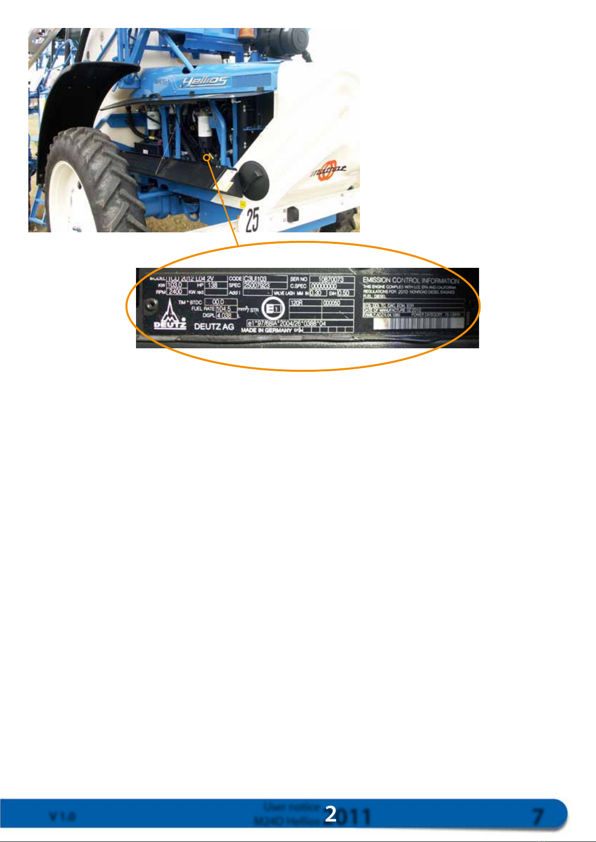
Identication of the self-propelled machine..............................................................................................................6
I. SAFETY .............................................................................................................................................................11
1.1. Safety stickers..................................................................................................................................................11
1.2. Safety hammer ...............................................................................................................................................16
1.3. General safety information..............................................................................................................................16
II. TECHNICAL CHARACTERISTICS ..............................................................................................................17
General description of M24D Hellios ....................................................................................................................18
III. CONTROLS...................................................................................................................................................20
IV. OPERATING THE SELF-PROPELLED MACHINE ....................................................................................23
4.1. Adjusting the steering wheel............................................................................................................................ 23
4.2. Adjusting the seat............................................................................................................................................23
4.3. Lighting and indications..................................................................................................................................24
4.4. Adjusting the rear view and wing mirrors ........................................................................................................25
4.5. Heating and air conditioning ..........................................................................................................................26
4.5.1. Control panel...............................................................................................................................................26
4.5.2. ON/OFF ..................................................................................................................................................... 26
4.5.3. Digital screen ...............................................................................................................................................26
4.5.4. Temperature sensor.......................................................................................................................................26
4.5.5. Setpoint .......................................................................................................................................................27
4.5.6. Ventilation ...................................................................................................................................................27
4.5.7 Air conditioning and Heating........................................................................................................................ 28
4.5.8. Demisting, De-icing..................................................................................................................................... 29
4.5.9. System parameters........................................................................................................................................30
4.6. Brakes .............................................................................................................................................................31
4.6.1. Hydrostatic brake.........................................................................................................................................31
4.6.2. Foot brake....................................................................................................................................................31
4.6.3. Parking brake ...............................................................................................................................................31
V. STARTING THE ENGINE.............................................................................................................................. 32
5.1. Pre-start checks................................................................................................................................................32
5.2. Filling with diesel ............................................................................................................................................ 33
5.3. Starting the engine ..........................................................................................................................................33
5.3.1. Start-up........................................................................................................................................................33
5.3.2. Causes of incorrect start-up.......................................................................................................................... 34
5.3.3. Engine speed................................................................................................................................................34
5.3.4. Monitoring the engine .................................................................................................................................34
5.4. Movement....................................................................................................................................................... 34
5.4.1. Selecting speeds............................................................................................................................................ 34
5.4.3. Stopping the engine .....................................................................................................................................36
5.4.4. Towing .........................................................................................................................................................37

2011 9
Notice d’utilisation
M24D Hellios
V 1.0
5.5. Rear steering....................................................................................................................................................38
5.5.1. Driving on the road ..................................................................................................................................... 38
5.5.2. Driving in elds ........................................................................................................................................... 39
5.5.3. Quick repairs for rear steering ......................................................................................................................41
5.6. Extending / retracting the booms .................................................................................................................... 42
5.6.1. Extending the booms ................................................................................................................................... 43
5.6.2. Retracting the booms ...................................................................................................................................45
VI. MAINTENANCE........................................................................................................................................... 46
6.1. Hydrostatic transmission.................................................................................................................................46
6.1.1. Filtration Filtration.......................................................................................................................................46
6.1.2. Top up with oil and check level .................................................................................................................... 47
6.1.3. Precautions after changing lter cartridges or oil .......................................................................................... 48
6.1.4. Practical tips................................................................................................................................................. 48
6.2. Adjusting hydraulic pressure............................................................................................................................ 50
6.2.1. e distribution unit >(lifting, extension & retraction of booms; deployment, slopes) ................................50
6.2.2. e spray pump control distributor (Photo 87)........................................................................................... 50
6.2.3. Hydrostatic pump (forward movement) .......................................................................................................51
6.2.4. Adjusting up/down speed............................................................................................................................. 51
6.2.5. Adjusting boom extension speed and slope correction ..................................................................................51
6.2.6. Pump and engine pressure tap......................................................................................................................52
6.3. Connections circuit.........................................................................................................................................52
6.4. Mechanical transmission ................................................................................................................................. 53
6.4.1. Driving axle (ground clearance = 1 m, depending on the tyre tting) ........................................................... 53
6.4.2. Driving axle (ground clearance = 1.3 m or 1.6 m, depending on the tyre tting).......................................... 54
6.4.3. Transfer gearbox ...........................................................................................................................................54
6.4.4. Assisted front axle......................................................................................................................................... 55
6.5. Motor..............................................................................................................................................................56
6.5.1. Recommended lubrication ........................................................................................................................... 56
6.5.2. Drainage period ........................................................................................................................................... 56
6.5.3. Air lter .......................................................................................................................................................57
6.5.4. Oil lter ....................................................................................................................................................... 58
6.5.5. Fuel lters ....................................................................................................................................................58
6.5.6. Exhaust and intake manifold connectors ......................................................................................................59
6.5.7. Engine cooling system..................................................................................................................................59
6.6. Type of oil and capacity...................................................................................................................................60
6.6.1. Motor...........................................................................................................................................................60
6.6.2. Transmission components ............................................................................................................................ 60
6.7. Greasing..........................................................................................................................................................61
6.8. Relays and Fuses.............................................................................................................................................. 66
6.9. Filtration......................................................................................................................................................... 68
VII. AIR CIRCUIT ...............................................................................................................................................69
VIII. SUSPENSION ............................................................................................................................................. 69
IX. Table of tyre ttings.......................................................................................................................................... 71
9.1. M24D Hellios 25 km/h tyre ttings................................................................................................................71
9.2. M24D Hellios 40 km/h tyre ttings................................................................................................................72

10 2011
Notice d’utilisation
M24D Hellios V 1.0
X. SPRAYING .......................................................................................................................................................73
10.1. Filling and Incorporation (By external suction): ............................................................................................ 77
10.2. Direct lling (Liquid fertiliser) - Position 3B................................................................................................. 80
10.3 Intensive mixing - Position 1A + R0............................................................................................................... 81
10.4. Mixing and Spraying - Position 1 A...............................................................................................................81
10.6. Spray arms (rinsing tank suction) - Position 5 C............................................................................................82
10.7. Spray arms (main tank suction) - Position 5 A............................................................................................... 82
10.8. Transfer (main tank to external tank) - Position 4 A ...................................................................................... 82
10.9. Suction lter cleaning - 4 D ..........................................................................................................................83
10.10. Drainage of the main tank using the manual valve ......................................................................................84
10.11. Basic information on drift ........................................................................................................................... 85
10.12. Winter storage.............................................................................................................................................85
XI. CLEANING THE SPRAY...............................................................................................................................87
11.1. Washing the self-propelled machine after use.................................................................................................87
11.2. Cleaning nozzles ...........................................................................................................................................87
11.3. Checking nozzle ow ....................................................................................................................................87
XII. INTER-OPERATION STORAGE ................................................................................................................88
XIII. HOW TO ORDER PARTS..........................................................................................................................90
XIV. OPTIONS.....................................................................................................................................................91
14.1. Rear jet option ..............................................................................................................................................91
14.3. Residual volume spray option........................................................................................................................92
14.4. Cab-controlled residual volume dilution option ............................................................................................93
14.5. Section cutout using the joystick ...................................................................................................................94
14.6. Weather station .............................................................................................................................................94
14.7. DGPS-assisted self-steering and section cutout..............................................................................................94
XV. Deutz Liquid Crystal Display ......................................................................................................................... 95
15.1. General description ...................................................................................................................................... 95
15.2. Instruction manual ......................................................................................................................................96
15.2.1. Adjusting brightness and contrast ..............................................................................................................96
15.2.2. Using keys. ................................................................................................................................................96
15.2.3. Main mode display ....................................................................................................................................96
15.2.4. 4-screen mode display ...............................................................................................................................97
15.2.5. Graphic mode display ................................................................................................................................98
15.2.6. Parameters which can be selected in graphic mode and Display of engine failures and failure codes ...........98
15.2.7. Conguration (Access code 1111) ........................................................................................................... 100

2011 11
User notice
M24D Hellios
V 1.0
1
2
3
67
5
4
89
10 11
12
16
17
13 14
15
20
19 21
18
I. SAFETY
Please comply with all rules in relation to caution and safety when using the
machine, or servicing the machine.
The manufacturer reminds users that common sense, planning ahead and
thinking are the key factors in safety.
1.1. Safety stickers
Please check the self-propelled machine with reference to the manual and read the information provided in the
form of safety pictograms, with any users.
These labels must be visible and be replaced if damaged.

12 2011
User notice
M24D Hellios V 1.0
148 247 000
22
23
24
231 286 000
231 277 000 231 279 000
Appropriate lifting point.
Label 1 and 20 Label 2
Fit the safety bolt when
travelling on the road or in
a field and for any boom
servicing.
Label 3
Beware of the risk of
electrocution or an electrical
shock.
Do not extend or retract the
booms under an electrical
cable.
For more information:
www.sousleslignes-prudence.
com
Label 4
Adjust the track and
forward speed to
conditions in the field.

2011 13
User notice
M24D Hellios
V 1.0
148 238 000 148 242 000
231 284 000 231 283 000
Protection must be kept
in good condition and
closed before the machine
is restarted.
Label 5 Label 6
Remain at a distance if the
machine is operational or
undertaking a manoeuver.
Corrosive products.
Use the appropriate
personal protection
equipment (PPE)
For more information on
how to use PPE, refer to
EEC directive 89/656/EEC,
and directive 89/686/EEC
amended by Directives
93/68/EEC, 93/95/EEC
and 96/58/EC.
Label 7
Use the appropriate
personal protection
equipment (PPE) during
tank drainage operations.
For more information on
how to use PPE, refer to
EEC directive 89/656/EEC,
and directive 89/686/EEC
amended by Directives
93/68/EEC, 93/95/EEC
and 96/58/EC.
Label 8

14 2011
User notice
M24D Hellios V 1.0
231 280 000
148 245 000 148 249 000
231 287 000
231 220 000
235 222 000
Use the appropriate
personal protection
equipment (PPE) while
handling phytosanitary
products.
For more information on
how to use PPE, refer to
EEC directive 89/656/
EEC, and directive 89/686/
EEC amended by directives
93/68/EEC, 93/95/EEC
and 96/58/EC.
Beware of moving belts
and pulleys.
Do not open or remove
guards while the engine is
running.
Be careful if you must
carry out a task near to the
engine cooling turbine :
Cut the engine.
Tank drainage valve.
Comply with applicable
legislation on the disposal
of phytosanitary products
and fertilisers.
Label 9 Label 10
Fresh water tank
Non-potable
water
Label 11
Label 12
Beware of mixing hopper
offset during descent.
Label 13 Label 14

DIESEL
OIL
OEL
OIL
2011 15
User notice
M24D Hellios
V 1.0
148 243 000
235 221 000
148 256 000
148 257 000
148 244 000
148 254 000
148 253 000
Label 15 Label 16
No person may remain
on the platforms and/or
ladders during machine
movement.
Label 17
It is formally prohibited to
enter the tank.
Toxic vapours or gases.
Label 18
Label 19 Label 21
Do not service working
tools when lifted.
You are recommended to
lower tools until they reach
their mechanical travel
stops, for example.
Turn the ignition key to
cut the engine.
Never cut the engine using
the cutout switch.
Label 22
Use diesel available on sale
from any service station
containing less than 0.5%
sulphur.
Orifice for adding oil for
the hydraulic controls of
the self-propelled machine
Risks of burns and
electrification

16 2011
User notice
M24D Hellios V 1.0
148 237 000
148 236 000
Label 24
1.2. Safety hammer
An emergency "glass breaker" hammer is located on the right
upright of the cab.
Use this hammer to break the side and rear windows and exit the
vehicle if necessary.
1.3. General safety information
- Generally, if the driver must leave the cab, the following actions should be completed first:
•Stopthespraypump;
•Settheparkingbrake;
•Cutthecombustionengine.
- Use caution when dismantling components.
-
When dismantling spray components, avoid spilling product on the soil.
- When dismantling heavy parts, place props under the parts in question.
- Dismantle hoses with caution.
- No residual pressure must remain in the circuit.
- Prepare a container to collect any oil spillage.
- Make sure the tools are in their resting position.
Refer to these instructions
for information on a
specific operation.
For all servicing and
adjustment operations,
cut the engine, remove
the key and refer to these
instructions.
Label 23

2011 17
User notice
M24D Hellios
V 1.0
Forward speed
M24D Hellios M24D 40 hare
Spraying 0 - 11 km/h 0 - 15 km/h
0 - 15 km/h 0 - 18 km/h
0 - 18 km/h 0 - 22 km/h
Road 0 - 25 km/h 0 - 40 km/h
DRIRE approval. Tyres as standard. Non-contractual data. May vary depending on the tyre ttings.
II. TECHNICAL CHARACTERISTICS
Engine - Model: M24D Hellios
Type :
Deutz TCD 2012 L04 2V
Cooling : fluid:
Number of cylinders : 4, inline
Displacement in cm3: 4 038
Air filter: : dry
Capacity : 103 kW (140 DIN HP)
Rotations per minute: 2,400
Transmission
2-wheel drive 4-wheel drive
1 pump 1 pump
1 twin engine 1 twin engine
Driving axle with 2 differential servo motors
which automatically block the front wheels
Brakes
Service brakes : disc
Parking brakes : disc
Steering
Hydrostatic with 4 turning wheels
Adjustable-angle steering wheel
Turn circle of 3.60 metres with 4 turning
wheels (track: 2.25 m)
Dimensions
Variable depending on equipment fitted.
Suspension
Constant height, pneumatic
3 tanks
Cab
Panoramic, pressurised, soundproofed
Pantograph windscreen wipers
Windscreen washer
Centralised controls
Electronic heating & air conditioning
controller
Activated carbon filter
CLINAIR
®
Electrical equipment
12 Vdc - 160 A battery
12 Vdc - 95 A alternator
Rotating beacon
Iodine work lights
Lighting and indications
Hydraulic fluid tank level alarm
Coolant level alarm
Tanks
Fuel: 170 litres
Hydraulic: 80 litres
Tyres
Depending on the options selected by the
customer
Tracks
1.80 m – 2.40 m (depending on the self-
propelled model, axles and tyre fittings)

18 2011
User notice
M24D Hellios V 1.0
General description of M24D Hellios
Front , rear

2011 19
User notice
M24D Hellios
V 1.0
Left side , right side

20 2011
User notice
M24D Hellios V 1.0
III. CONTROLS
1 Parking brake lever
2 Spray pump speed adjuster knob
3 Windscreen washer tank
4 Engine control screen
5 Alternator charge indicator
6 Parking brake indicator
7 Airltercloggingindicator
8 Speed range 1 indicator
9 Speed range 2 indicator
10 Left turning indicator light
11 Switch: turning indicators, horn, low beam – full beam
12 Control pedal
13 Engine incident troubleshooting indicator
14 Hydraulicuidlevelindicator
15 Combustion engine pre-heating indicator
16 Low beam indicator
17 Full beam indicator
18 Right turning indicator light
19 Combustion engine cutout/ignition key contact
20 Emergency brake pedal
21 Fuel gauge
22 and 48 Right boom
23 and 33 Left boom
24 Main boom cross-section
25 Slope correction
26 and 32 Front frame lift and descent
27 Joystick
28 Boom section switches
29 Travelstopindicator,controlvalveclosed(positionR10)
30 Travelstopindicator,controlvalveopen(positionR0)
31 Boom command main ON/OFF switch
34 Extending / retracting the outer left arm
35 Extending / retracting the main arms
36 Boomsafetydevicelock/releasecontactor
37 Speed range 1 / 2 control switch
38 Rearjettankresidualvolumedrainagepumpswitch
39 Tankresidualvolumedilutionpumpswitchinthecab
40 Rear power switch
41 Left lateral jet switch
42 Right lateral jet switch
43 Rear steering controls
44 Rear steering power switch
45 Boom arm control switches
46 Extending / retracting the outer right arm
47 Gear stick
50 Main spray operation indicator
51 Solenoidvalvecontrol–mixing/residualvolumeinthetank
52 Centrifugal pump ON/OFF control
53 Engine accelerator
54 "Teejet 860" control panel
55 DGPS module*
56 12 V plug
57 Deutz engine troubleshooting socket
58 Hazard lights switch
59 Glovebox
Table of contents
Other Matrot Paint Sprayer manuals