manuals.online logo
Brands
  1. Home
  2. •
  3. Brands
  4. •
  5. Graco
  6. •
  7. Paint Sprayer
  8. •
  9. Graco AllControl 288711 User manual

Graco AllControl 288711 User manual

This manual suits for next models

1

Other Graco Paint Sprayer manuals

Graco 233889 User manual

Graco

Graco 233889 User manual

Graco TEXTURE 240–786 Operation manual

Graco

Graco TEXTURE 240–786 Operation manual

Graco 278680 User manual

Graco

Graco 278680 User manual

Graco RAZOR 288588 Operation manual

Graco

Graco RAZOR 288588 Operation manual

Graco TexSpray 234113 Instruction Manual

Graco

Graco TexSpray 234113 Instruction Manual

Graco EM 390 Operation manual

Graco

Graco EM 390 Operation manual

Graco 241705 Operation manual

Graco

Graco 241705 Operation manual

Graco DutyMax 24M054 Instruction Manual

Graco

Graco DutyMax 24M054 Instruction Manual

Graco 238-588 User manual

Graco

Graco 238-588 User manual

Graco MAGNUM TRUEAIRLESS DIY Series User manual

Graco

Graco MAGNUM TRUEAIRLESS DIY Series User manual

Graco Series A User manual

Graco

Graco Series A User manual

Graco PROX19 User manual

Graco

Graco PROX19 User manual

Graco TexSpray RTX 750 Operating instructions

Graco

Graco TexSpray RTX 750 Operating instructions

Graco Wall Mount Series Datasheet

Graco

Graco Wall Mount Series Datasheet

Graco ULTRA 500 231-032 Operation manual

Graco

Graco ULTRA 500 231-032 Operation manual

Graco 220–856 D Series User manual

Graco

Graco 220–856 D Series User manual

Graco 245095 Assembly instructions

Graco

Graco 245095 Assembly instructions

Graco M2K 17D763 Parts list manual

Graco

Graco M2K 17D763 Parts list manual

Graco 311736A User manual

Graco

Graco 311736A User manual

Graco 232903 Operating instructions

Graco

Graco 232903 Operating instructions

Graco XM 24W626 User manual

Graco

Graco XM 24W626 User manual

Graco XM Series User manual

Graco

Graco XM Series User manual

Graco GMx 7900 User manual

Graco

Graco GMx 7900 User manual

Graco REACTOR 246033 User manual

Graco

Graco REACTOR 246033 User manual

Popular Paint Sprayer manuals by other brands

Idex Akron Brass FS100 quick start guide

Idex

Idex Akron Brass FS100 quick start guide

mbp TEL 15BS instructions

mbp

mbp TEL 15BS instructions

Solo 425 Classic Original instructions

Solo

Solo 425 Classic Original instructions

WAGNER AirCoat GM 4100 AC operating manual

WAGNER

WAGNER AirCoat GM 4100 AC operating manual

Titan MultiFinish 440 owner's manual

Titan

Titan MultiFinish 440 owner's manual

SNOWJOE Sunjoe 24V-GS-LTW-RM Operator's manual

SNOWJOE

SNOWJOE Sunjoe 24V-GS-LTW-RM Operator's manual

Walther FSP-01 Assembly instructions

Walther

Walther FSP-01 Assembly instructions

Fimco LG-4-3-1 owner's manual

Fimco

Fimco LG-4-3-1 owner's manual

Nordson MicroMax 2 manual

Nordson

Nordson MicroMax 2 manual

Bonide 051 Operation and service instructions

Bonide

Bonide 051 Operation and service instructions

zogics Z-DAS instruction manual

zogics

zogics Z-DAS instruction manual

KISANKRAFT KK-KBS-165 Operation manual

KISANKRAFT

KISANKRAFT KK-KBS-165 Operation manual

Matrix SG 650 Translation of the original instructions

Matrix

Matrix SG 650 Translation of the original instructions

paasche VV Instructions and parts list

paasche

paasche VV Instructions and parts list

Carlisle DeVilbiss JGA-510 Service manual
Carlisle

Carlisle DeVilbiss JGA-510 Service manual
Gardena 11120 Operator's manual

Gardena

Gardena 11120 Operator's manual

DeVilbiss LUNA2i Operation manual

DeVilbiss

DeVilbiss LUNA2i Operation manual

WAGNER W 125 manual

WAGNER

WAGNER W 125 manual

manuals.online logo
manuals.online logoBrands
  • About & Mission
  • Contact us
  • Privacy Policy
  • Terms and Conditions

Copyright 2025 Manuals.Online. All Rights Reserved.

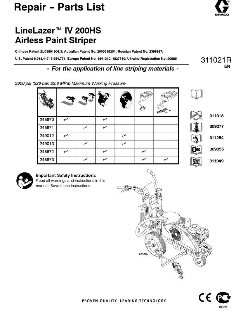
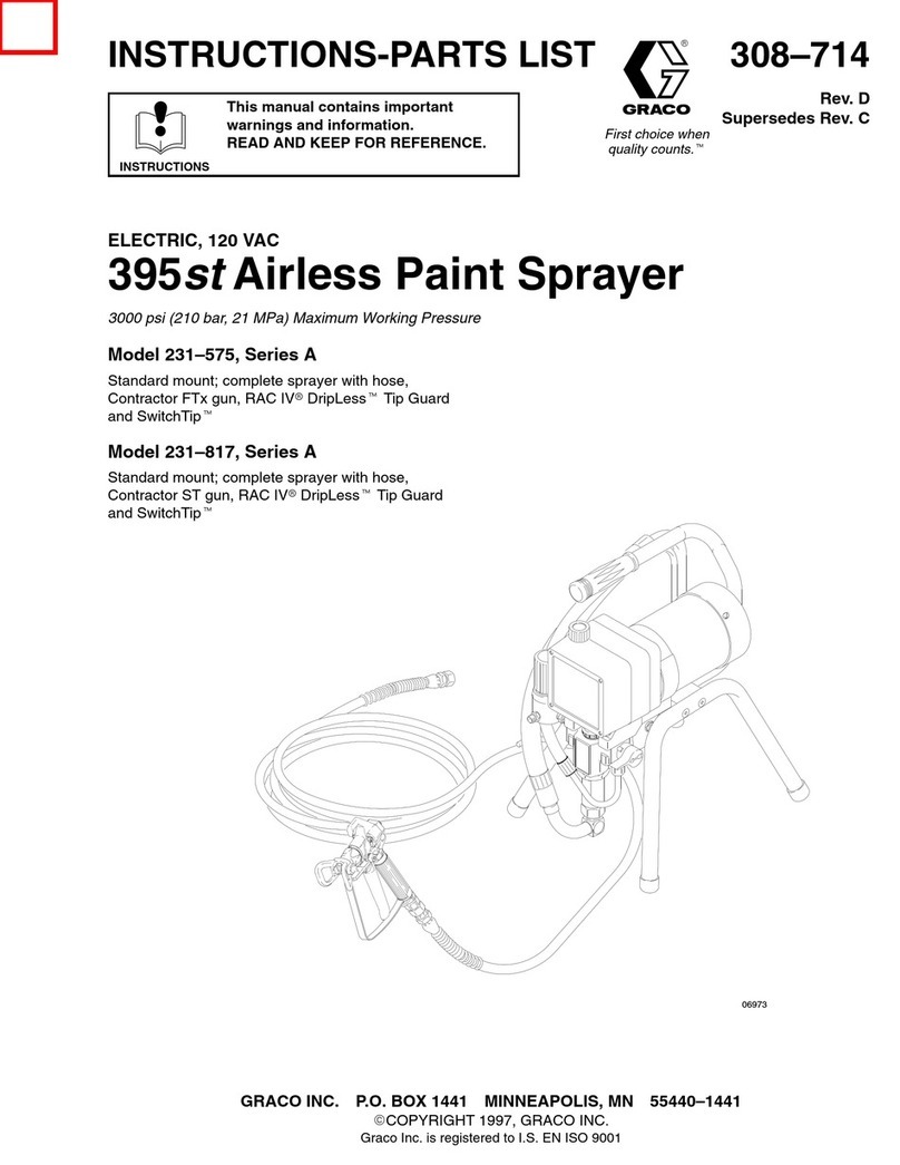
Graco Inc. P.O. Box 1441 Minneapolis, MN 55440-1441
Copyright 2007, Graco Inc. is registered to I.S. EN ISO 9001
312290A
Instructions
AllControl Repair Kits 288711, 289210
Model 288711: Use with MAGNUM Project Painter 7 Sprayers
Model 289210: Use with MAGNUM Project Painter 5 Sprayers
Maximum Working Pressure: 3000 psi (21 MPa, 207 bar)
Important Safety Instructions
Read all warnings and instructions in this manual. Save these instructions. For detailed sprayer
information and warnings, see your Operation manual.
To reduce the risk of fluid injection or splashing in the
eyes or on the skin, relieve all fluid pressure in
system before you install, remove, or replace any
parts. See the Pressure Relief Procedure provided
in your Operating Instruction manual.
CAUTION
When repairing or cleaning the pump, never sub-
merge the pump in water or allow fluid to enter the
pressure control
2312290A
Project Painter 7: 261805
Disassembly
1 Unplug electrical cord, and relieve pressure.
2 Remove suction tube, drain line and coupled hose.
3CutAllControl labels at two places where upper and
lower housings mate (A).
4 Fig. 1. Remove two screws (B) (support sprayer with
hand) and remove sprayer from frame.
5 Fig. 2. Put AllControl knob in ROLL position. Remove
four screws (C) and motor shroud.
6 Fig. 1. Squeeze pressure control connector (D) and
disconnect from control board.
7 Fig. 2. Remove one screw (E) and control board.
8 Remove four screws (F) from pump housing.
9 Turn sprayer with drive housing face up. Wiggle drive
housing and remove.
10 Fig. 3. Remove two screws (G) from pressure control
mounting plate.
11 Remove pressure control assembly from pump housing.
FIG. 1
Assembly
1 Grease o-ring on pressure control assembly. Push
pressure control down into machined slots in pump
housing. Ensure wires are not pinched. Secure with two
screws (G). Torque to 40 ±5 in-lb.
2 Align gears in drive housing with pump housing and
assemble housings. Keep drive housing and pump
housing together and turn sprayer with drive housing face
down,
3 Install four screws (F) and secure pump housing to drive
housing. Torque 30 ±5 in-lb.
4 Install control board with one screw (E). Torque 30 ±5
in-lb.
5PlugAllControl harness into control board (D). Align
electrical cord strain relief in drive housing.
6PutAllControl knob in ROLL position. Install four screws
(C) and motor shroud. Torque 30 ±5 in-lb.
7 Install sprayer in frame with two screws (B).
Torque 75 ±5 in-lb.
8 Remove old labels and install new labels (A).
9 Install coupled hose, drain line and suction tube.
FIG. 2
CAUTION
Be careful not to damage wires on disassembly/assembly.
PP7 WIRING DIAGRAM
ALL CONTROL
AUTO PRIME
10A FUSE
ti10242a
ti10227a
A
B
D
C
E
F
ti10240a
312290A 3
FIG. 3
ti10287a
G
4312290A
Project Painter 5: 261800
Disassembly
1 Unplug electrical cord, and relieve pressure.
2 Remove suction tube, drain line and coupled hose.
3 Fig. 4. Cut AllControl labels at two places where upper
and lower housings mate (A).
4 Remove four screws (B) and base tube
5 Fig. 5. Stand sprayer in upright position. Remove four front
cover screws (C). Put
AllControl
knob in
ROLL
position.
6 Fig. 5. Remove front cover subassembly from base and
place face down on bench.
7 Fig. 4. Disconnect pressure control connector (D) from
control board.
8 Remove six screws (E) from pump housing.
9 Fig. 6. Turn sprayer with drive housing face up. Wiggle
drive housing and remove.
10 Remove two screws (F) from pressure control mounting
plate.
11 Remove pressure control assembly from pump housing.
FIG. 4
Assembly
1 Grease o-ring on pressure control assembly. Push
pressure control down into machined slots in pump
housing. Secure with two screws (F). Torque to 40 ±5 in-lb.
2 Align gears in drive housing with pump housing and
assemble housings. Keep drive housing and pump
housing together and turn sprayer with drive housing face
down,
3 Install pump housing to drive housing with six screws (E).
Torque 29 ±3 in-lb.
4PutAllControl knob in ROLL position.
5PlugAllControl harness connector (D) into control board.
Align electrical cord strain relief in drive housing.
6 Install sprayer in base with four screws (C).
Torque 29 ±3 in-lb.
7 Install base tube on frame with four screws (B).
Torque 29 ±3 in-lb.
8 Remove old labels and install new labels (A).
9 Install coupled hose, drain line and suction tube.
FIG. 5
CAUTION
Be careful not to damage wires on disassembly/assembly.
PP5 WIRING DIAGRAM
ALL CONTROL
10A FUSE
ti10241a
ti10288a
A
B
D
C
ti10289a
312290A 5
FIG. 6
F
E
ti10290a
6312290A
All written and visual data contained in this document reflects the latest product information available at the time of publication.
Graco reserves the right to make changes at any time without notice.
GRACO INC. P.O. BOX 1441 MINNEAPOLIS, MN 55440-1441
www.graco.com
6/2007