This manual suits for next models
1
Table of contents
Other Matsushita Electric Tape Deck manuals
Matsushita Electric
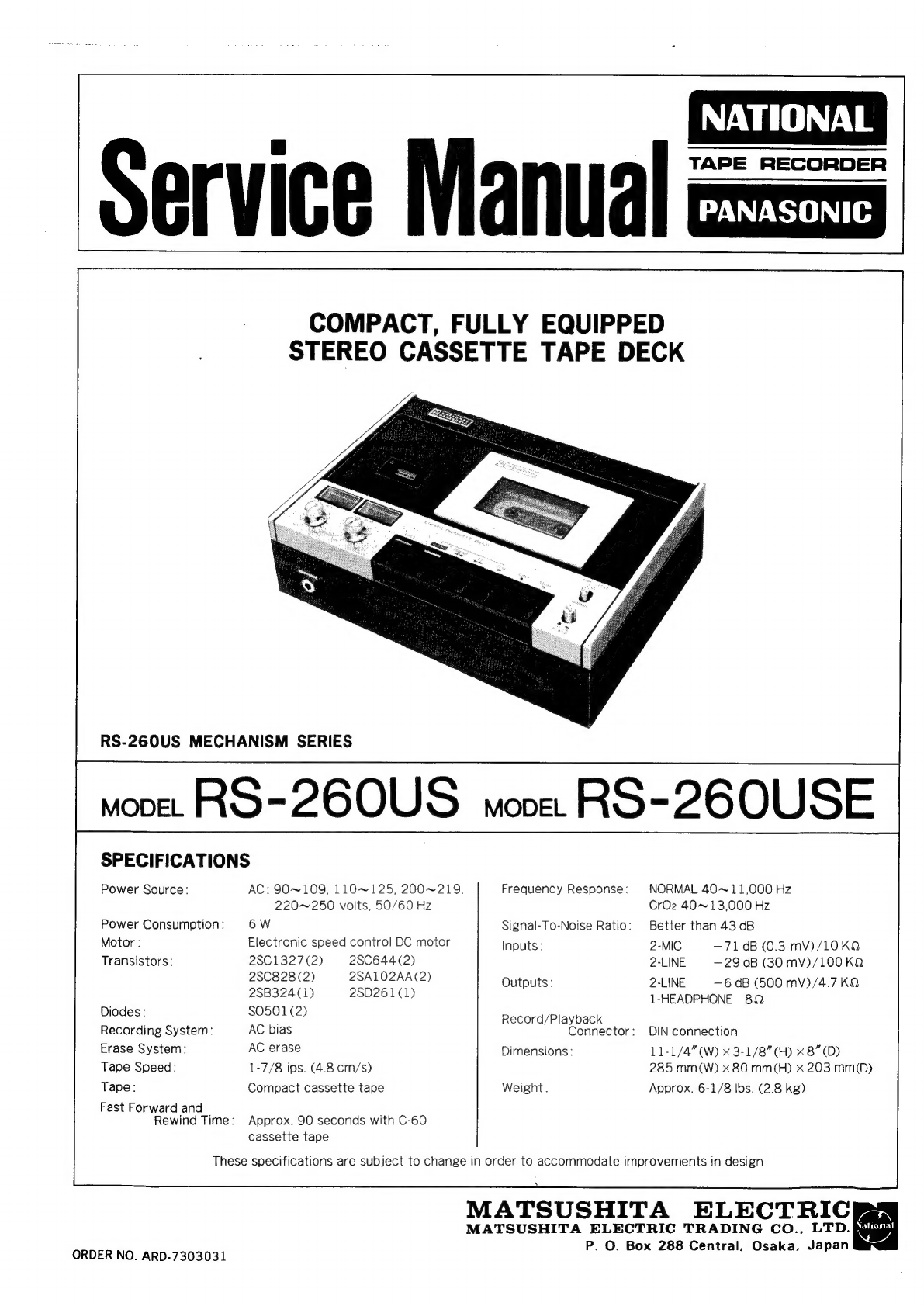
Matsushita Electric PANASONIC RO-260US User manual
Pioneer
Pioneer RT-1020L operating instructions
3M
3M 3M-Matic Dual S-867 II Instructions and parts list
Pioneer GT-X5 Service manual
SilverStone
SilverStone 1232 manual
Teac
Teac X-2000 owner's manual
Hitachi
Hitachi D-980MU Service manual
Teac A-6010GSL Service manual
Hitachi D-900BS Service manual
Kyocera
Kyocera D-611 Service manual
Kenwood
Kenwood KX-W595 instruction manual
TANDBERG
TANDBERG 11 instruction manual
Teac Tascam 3030 owner's manual
Sony
Sony DTC-670 operating instructions
Teac A-3300 Service manual
Pioneer H-R99 KCU Service manual
Kenwood KX-W6070 instruction manual
Sony DTC-A8 Service manual
Tascam
Tascam BR-20 Series maintenance