Max Machinery 284-512 SERIES User manual

INSTRUCTION MANUAL
284-512 SERIES
TRANSMITTER
TABLE OF CONTENTS
General Description . . . . . . . . . . . . . . . . . . . . . . . . . . . Pg 1
Specifications . . . . . . . . . . . . . . . . . . . . . . . . . . . . . . . Pg 2
Installation . . . . . . . . . . . . . . . . . . . . . . . . . . . . . . . . . . Pg 3
Temperature Limits . . . . . . . . . . . . . . . . . . . . . . . . . . . Pg 5
Signal Transmission Data . . . . . . . . . . . . . . . . . . . . . . Pg 5
Temperature Limit Graphs . . . . . . . . . . . . . . . . . . . . . . Pg 6
Signal Transmission Graphs . . . . . . . . . . . . . . . . . . . . Pg 7
K-Factor . . . . . . . . . . . . . . . . . . . . . . . . . . . . . . . . . . . . Pg 8
Photo Disk Assembly . . . . . . . . . . . . . . . . . . . . . . . . . Pg 9
General Flow Metering Considerations . . . . . . . . . . . . Pg 10
All schematics are available by contacting MMI Technical Service:
286-700-010
284-510-200
181-000-250
284-512-350 © 1990 (Rev 6/97) Max Machinery, Inc.
Max Machinery, Inc. reserves the right to make changes to the product in this Instruction
Manual to improve performance, reliability, or manufacturability. Consequently, contact
MMI for the latest available specifications and performance data.
Although every effort has been made to ensure accuracy of the information contained in this
Instruction Manual, MMI assumes no responsibility for inadvertent errors.
Discontinued

Page 2 284-512-350 © 1990 (Rev 6/97) Max Machinery, Inc.
General Description
General Description
The 284-512 transmitter is a photo optic device which converts the rotary motion of a typical
Max flow meter into an electrical signal whose frequency is proportional to the flow meter
RPM. It has two output formats: a square wave of 100 cycles per revolution and a two phase
output of 50 cycles per revolution. The single phase output has an antidither feature, which
makes it useful for low flow zero velocity applications which may involve momentary
reverse flows. A memory circuit will hold up to 128 pulses of negative flow, outputting only
the net forward flow. The two phase output is useful for bi-directional applications. Both
outputs are CMOS and TTL compatible and are generally able to drive at least 1000 feet of
shielded cable.
The 284-512 can operate from a voltage source of 4.5 volts to 30 volts. A wide range on
board regulator protects the circuitry from transient supply noise. No adjustments are
required for different supply voltages.
Discontinued

284-512-350 © 1990 (Rev 6/97) Max Machinery, Inc. Page 3
Supply Voltage . . . . . . . . . . . . . . . . 4.5V to 30V DC
Supply Current . . . . . . . . . . . . . . . . 15mA / maximum
Output Impedance . . . . . . . . . . . . . Less Than 500 Ohms
Output Voltage High Low
No Load . . . . . . . . . . . . . . . . . . . 5.0V 0.0V
2.5K Load to Common . . . . . . . . 4.5V 0.0V
2.5K Load to +5V . . . . . . . . . . . . 5.0V 0.3V
Output Short Circuit Current* . . . . 13.75mATypical
Rise Time (2.5K Load) . . . . . . . . . 0.7 µs (90%)
Fall Time (2.5K Load) . . . . . . . . . . 0.4 µs (90%)
Output Frequency
Maximum . . . . . . . . . . . . . . . . . . 6000 Hz
Minimum . . . . . . . . . . . . . . . . . . 0.0 Hz
Antidither Range
(Single Phase Only) . . . . . . . . . . . . 128 cycles
1.28 revolutions
Disk RPM
Maximum RPM . . . . . . . . . . . . . 3600 RPM
Minimum RPM . . . . . . . . . . . . . . 0.0
Temperature Limits
Storage . . . . . . . . . . . . . . . . . . . . -65°C to 80°C
Operating . . . . . . . . . . . . . . . . . . -15°C to 65°C
(The temperature of the material flowing through the flow meter will typically affect the
operating temperature of the transmitter, see page 7).
* Sourcing. The 5V sink current is 32mA. Continuous short circuit is not recommended.
Specifications
Specifications
Discontinued

Page 4 284-512-350 © 1990 (Rev 6/97) Max Machinery, Inc.
Installation
Environment: The electrical circuitry of the weather-tight, explosion-proof transmitter is
enclosed in a liquid and vapor tight enclosure. All joints are sealed by welding or by “O”-
rings. If this sealed condition is to be maintained, the conduit connection to the enclosure
should be made liquid and vapor tight by using pipe dope or a potting fitting. If a transmitter
is located outside and this precaution is not taken, moisture may form inside the housing.
This will cause the circuitry to give
an inaccurate output or possibly no
output at all. In the long run it will
cause corrosion and failure. The
amphenol connector versions of the
284 offer moderate protection from
moisture and dust, but are not totally
sealed.
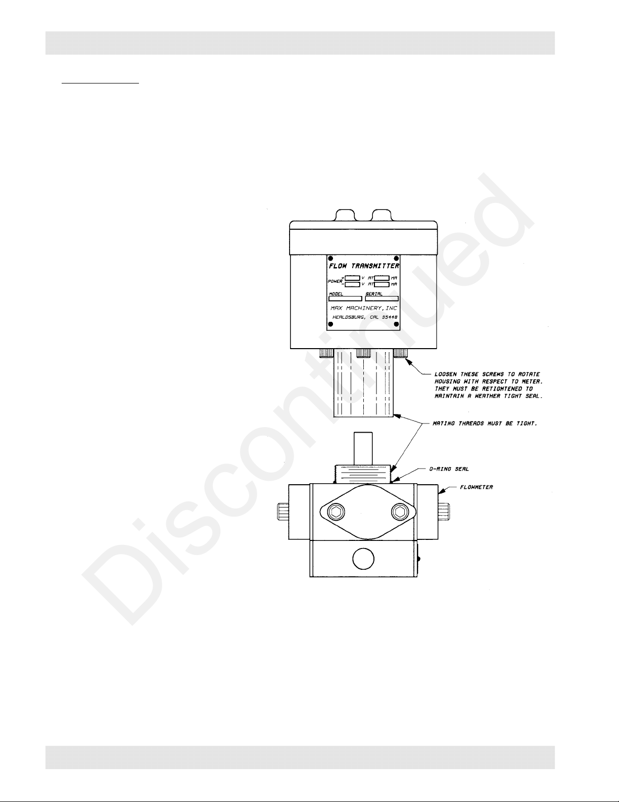
The transmitter may be rotated by
loosening the screws under the
housing (see drawing on Page 5).
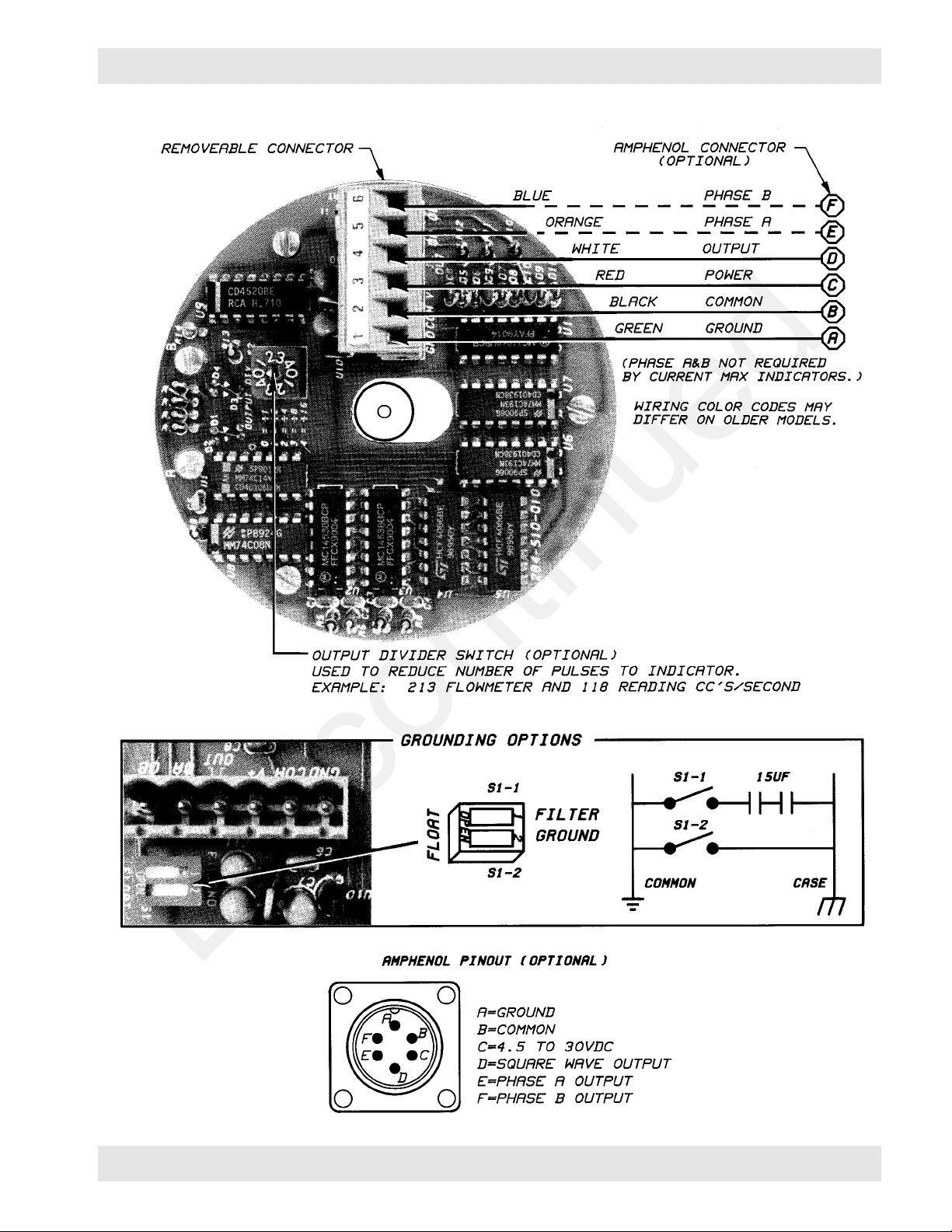
Connections: The facing page
shows the terminals and their
functions. When connecting wires to
the screw terminal versions, make
sure the lead wires do not rub on the
arbor. This arbor rotates and rubbing
wires will affect accuracy and may
eventually cause a short circuit.
Grounding: Two dip switches are
provided. The ground switch, when
activated, connects the circuit
common to the case terminal. The
Filter switch, when activated,
connects the circuit common to the
case via two back to back capacitors.
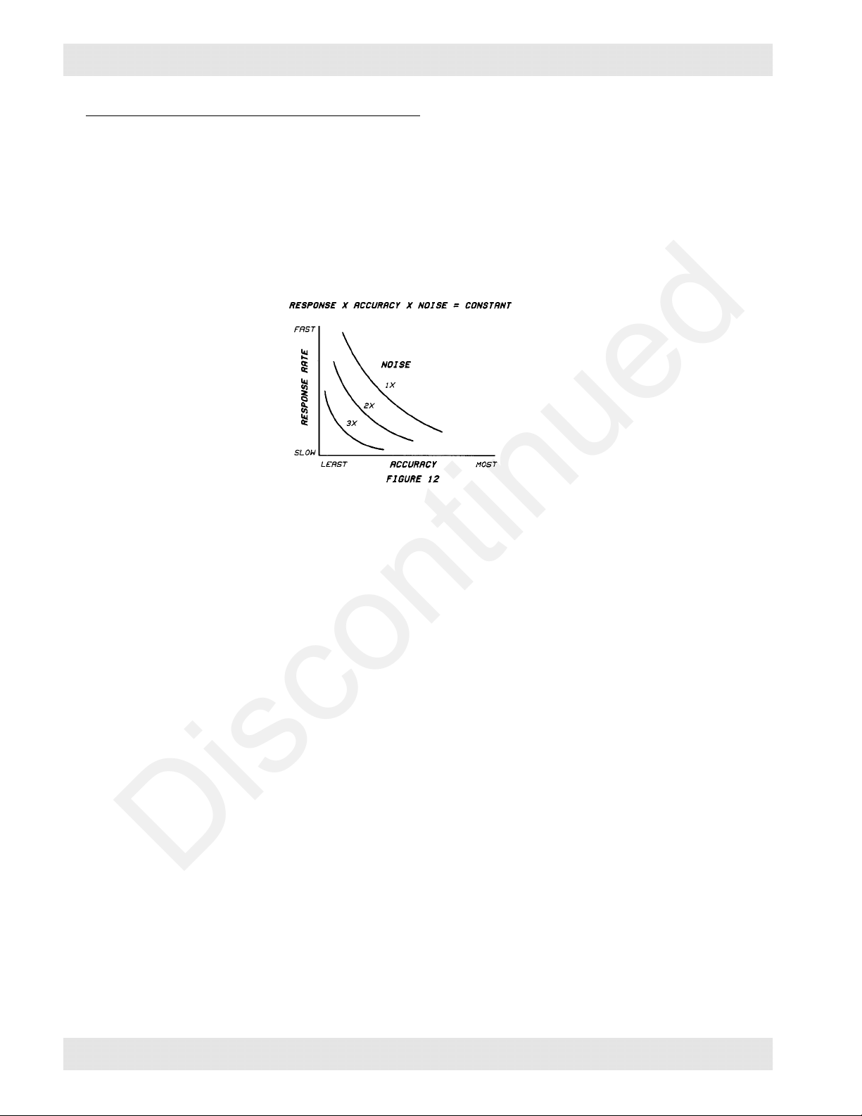
These two switches facilitate system
grounding procedures which will reduce electrical noise problems.
It is advisable to have the common of any system physically grounded at one point only. If
your system is grounded at the receiving end then you may not want to ground the common
at the transmitter end. In this case, it is advantageous to connect the circuit common to case
via the capacitors (filter). This will give some extra immunity to electrical noise.
Installation
Discontinued

284-512-350 © 1990 (Rev 6/97) Max Machinery, Inc. Page 5
Installation
Discontinued

Page 6 284-512-350 © 1990 (Rev 6/97) Max Machinery, Inc.
Temperature Limits
The electronic circuit of the 284 uses components which are intended to operate within the
range of -15°to +65°C (5°to 145°F). They will probably operate satisfactorily for brief
periods from -50°to +85°C, although this is not recommended.
The 284 is thermally connected to the flow meter body. For this reason, the temperature of
the 284 will be a function of ambient temperature and the flow meter temperature. The limit
of these two temperatures is interrelated, which is shown in Figures 6 and 7. Figure 6 is for
the 284 in a vertical position; Figure 7 is for the 284 in a horizontal position.
Temperature Limits
Discontinued

284-512-350 © 1990 (Rev 6/97) Max Machinery, Inc. Page 7
Signal Transmission Data
Figure 8 is a graph which
indicates typical conductor
capacitance loads versus cable
length for several types of
cable. For instance, 1000 ft. of
7 conductor # 18 gauge
stranded wire will put a 0.04 µf
capacitive load on the output of
the 284-512 series transmitters.
Figure 9 provides the
relationship between output
capacitance loading and rise
and fall time for the 284-512
output signal. For instance, at
0.04 µf, the rise time of the 284
is about 18 µsec, the fall time
is about 8.5 µsec.
Consequently, the absolute
maximum frequency the 284
could transmit would be 26.5 µ
sec = 37,736 Hz (frequency =
1/time). This frequency is well
above what any flow meter will
develop.
Generally, the 284-512 Series
transmitters will drive 1000
feet or more of cable with no
problem.
Signal Transmission Data
Discontinued

Page 8 284-512-350 © 1990 (Rev 6/97) Max Machinery, Inc.
K-Factor
K-factors represent the number of pulses the transmitter outputs per cubic centimeter (or
other engineering unit) of fluid passing through the flow meter. This number is dependent on
the flow meter - transmitter combination. MAX indicators can be adjusted to display the
desired flow engineering units (ccs, lbs, gallons, quarts, etc.) by using the K-factor.
Flow meters are individually multi-point calibrated at the factory and a graph of the K-factor
(which varies slightly with flow rate) provided to the customer. A typical calibration sheet is
shown below.
K-Factor
Discontinued

284-512-350 © 1990 (Rev 6/97) Max Machinery, Inc. Page 9
Photo Disk Assembly
The Max 210 Piston Series Flow Meters have a sinusoidal type motion superimposed on the
overall rotary motion. This motion, when coupled to the 284 through the magnetic drive
system, will cause the photo disk of the 284 to oscillate at the systems resonant frequency. For
this reason, there is a friction disk mounted between the arbor of the 284 and the photo disk.
If the photo disk and shaft assembly is to be disassembled, care should be taken when it is
reassembled. A small trace of molybdenum sulfide grease should be placed on the face and
bore of the brass arbor which the photo disk is fastened to. The locking collar must not be
forced up too tightly against the photo disk. About a 0.005 gap should be left, which allows
the disk some freedom of movement. The spring keeps the disk and shaft in synchronization.
Photo Disk Assembly
Discontinued

Page 10 284-512-350 © 1990 (Rev 6/97) Max Machinery, Inc.
Response Rate, Accuracy and Noise
There is always a trade off in a metering system between response rate, accuracy and noise.
The three are related such that their product equals a constant. If any one of them is made
smaller, the others can be made larger.
In most metering systems, response rate and accuracy are desirable characteristics. To
maximize one or both of these parameters, noise should be reduced to a minimum. Once
noise has been minimized, there is a trade off between accuracy and response rate.
Response Rate: When discussing response rate there are three facets to consider. They are:
the response of the flow to a change in the system setpoint, the correction of the flow to an
error induced in it, and the response of the flow rate display to a change in flow rates. These
responses are all purposely slowed down by filtering or damping so the system only reacts to
meaningful flow changes and not to such things as pump pulsations or flow meter ripple.
More damping means slower response.
Accuracy: There are three topics to consider when looking at accuracy. The first being the
display; which can typically have anywhere from two digits (1 to 99) to 4-1/2 digits (19,999)
of information. This equals a resolution of 1% to a maximum of 0.005%, respectively. The
display steadiness is also directly related to it’s accuracy. For instance, a display that jitters
from 95 to 105 in a meaningless way is not accurate to one part in 100 (1%) but only to about
10 parts in 100 (10%).
The basic accuracy of the flow meter is a prime consideration. Typically, the accuracy of a
positive displacement meter is not as good for a fraction of its cycle as it is for one or more
complete cycles. If a system is dampened so that the response rate is longer than the period
of one revolution of the meter, the accuracy of the display is increased. The accuracy of the
system can never be better than that of the flow meter.
Noise: Noise can be defined as any change in either the fluid flow or the electrical system
that is not a meaningful change in the flow rate. For instance, the ripple induced in the flow
by a gear or piston pump is noise. The system will typically have to be dampened so that its’
response time is longer than the tooth to tooth period of the pump. Piston pumps with fewer
than three pistons create a particularly large amount of bothersome ripple and result in a very
slowly responding system.
General Flow Metering Considerations
Discontinued

284-512-350 © 1990 (Rev 6/97) Max Machinery, Inc. Page 11
Response Rate, Accuracy and Noise (cont.)
All positive displacement flow meters add noise to a flow metering system. The noise is
typically of two origins. As the elements of the meter rotate, they require varying amounts of
pressure to move (See Fig. 13). This induces pressure fluctuations between the pump (or
control valve) and the flow meter. If there is any air trapped in the line, the fluid flow will
vary as the air compresses and expands. This will be sensed as a changing flow by the flow
meter and the output will contain unwanted ripple or noise. Plumbing in a flow system
should be sized and laid out to avoid air being trapped between the flow meter and the flow
controlling device (a pump or valve).
The second type of noise that must be considered is a result of flow meter geometry and
design. Because of features such as an oval gear, or a piston/crankshaft configuration, or due
to manufacturing tolerances, the rotation of the metering elements is not completely uniform.
For example, the 210 series meters utilize four pistons connected to a crankshaft. The
varying rotational speed of the crankshaft is shown in Fig. 14. To obtain the smoothest
output signal, some amount of damping will be necessary at the indicator.
The electronic converter of any meter will add its share of noise. For instance, DC
transmitters produce some ripple in their output due to the sinusoidal nature of the induced
voltage in the armature coils.
General Flow Metering Considerations
Discontinued

Discontinued

Discontinued

Discontinued
Table of contents
Other Max Machinery Transmitter manuals
Popular Transmitter manuals by other brands

Dwyer Instruments
Dwyer Instruments CDX Series Installation and operating instruction manual

Linx Technologies
Linx Technologies CMD-HHLR Series Guide

SUPMEA
SUPMEA U-SUP-WSR550-EN1 user manual

Emerson
Emerson Rosemount 702 quick start guide

Magnetrol
Magnetrol Jupiter JM4 operating manual

Intercoax
Intercoax Ipify ECP-2704R-4T-PKG Quick install guide