MAX PROP WHISPER 5 BLADES User manual

installation instructions
MAX PROP®WHISPER
patented propeller

2
INTRODUCTION
Thank you for choosing a feathering propeller MAX PROP®WHISPER. This instruction
manual will be used to answer all your questions about installation and use of the
propeller. It is very important to read it carefully and verify the correct operation of
the propeller before installing it on your boat.
INSTALLATION
Please carry out the various operations referring to g. 1. The propeller is supplied
already assembled for right or left rotation, according to information received when
the order was made, and with a specic required pitch, so that it can be directly
installed on the propeller shaft as a common xed-pitch propeller. We remind you
that MAX PROP®WHISPER parts are not interchangeable. If you receive more than one
propeller at the same time (for example if two propellers have to be installed on a
boat), and for any reason the received propellers are opened, you must therefore be
very careful not to mix the disassembled pieces.
a. Fit the already assembled propeller on the drive shaft, like a xed-pitch propeller,
verify that the key has the appropriate size: it should have clearance on the
upper surface in order to prevent the propeller from being brought off center, but
between the side surfaces there should be no clearance.
b. Tighten the nut and lock it by using the two locking-nut screws which should be
inserted and tighten into the proper seats.
Fig. 1
ALBERO MOTORE - SHAFT
CHIAVETTA - KEY
ELICA - PROPELLER
ZINCO - ZINC
VITI BLOCCA DADO
BLOCKING NUT SCREWS
DADO - NUT
VITI BLOCCA ZINCO
BLOCKING ZINC SCREWS

3
c. Fill the propeller with marine grease through the appropriate holes by using a
lubrication tool. The MAX PROP®WHISPER propeller works properly only if
completely lled with uid grease. Verify that the grease seeps from the joints
through the rotating parts (the hub and the blades) and the propeller body, so as to
be sure that all of the rotating surfaces are perfectly greased. The grease must be
uid to ensure that it will continue to seep from said joints even after years of use.
d. Orient the blades in the feathered position (i.e. perfectly in line with the axis of
the propeller body), making sure that their prole is as shown in g. 2.
e. Before launching the boat, it is absolutely necessary to operate as follows:
• Lock the propeller shaft.
• Verify that the propeller blades rotate freely from the forward motion position
to the backwards motion position simply by hand pushing; at the end of the
stroke, they must have a blade angle preset by the user and the same direction
of rotation of the engine.
• In the feathered position the blades must be perfectly aligned and oriented as
in g. 2.
• Verify that the propeller is full of uid marine grease.
• Make sure that the propeller is protected from galvanic corrosion by applying the
proper zinc anodes on the propeller and drive shaft.
Fig. 2

4
1 18062014
MAX PROP EASY
INTRODUZIONE
Grazie per aver scelto un’elica a pale orientabili MAX
PROP® EASY. Questo libretto di istruzioni servirà a
rispondere a tutte le Vostre domande sul montaggio e
sull’uso dell’elica. Vi consigliamo di leggerlo
attentamente e di fare la verifica del corretto
funzionamento dell’elica prima di montarla sulla Vostra
imbarcazione.
MONTAGGIO
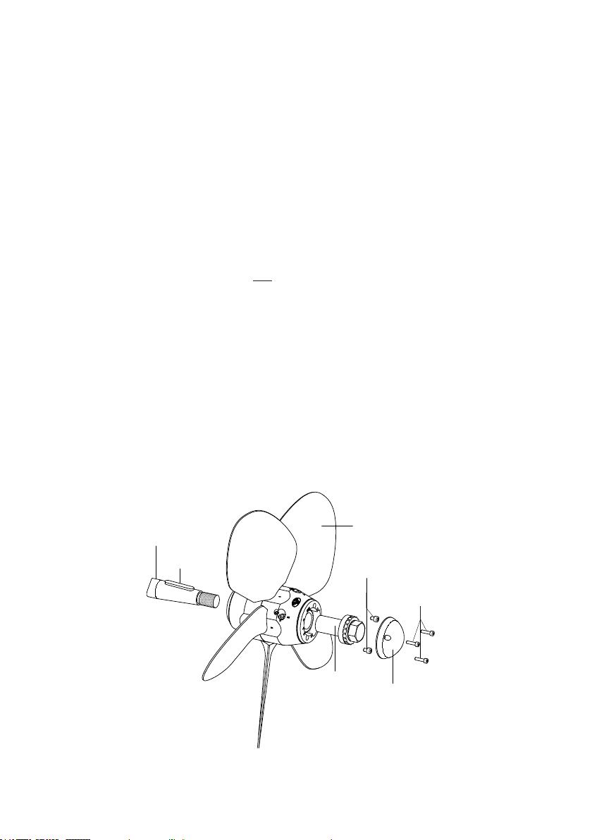
Effettuate le varie operazioni facendo riferimento alla fig.
1. L’elica è fornita già assemblata come destrorsa o
sinistrorsa secondo l’informazione ricevuta al momento
dell’ordine, e con un determinato passo richiesto, così
che possa essere montata direttamente sull’albero
motore. Tenete presente che le parti che compongono la
MAX PROP® EASY non sono intercambiabili. Nel caso si
ricevessero contemporaneamente più eliche, sarà quindi
necessario fare molta attenzione a non mischiare i pezzi
smontati.
a) Inserite l’elica già assemblata sull’asse motore,
come fosse un’elica fissa, verificate che la linguetta
sia di misura appropriata: che abbia gioco sulla
faccia superiore per evitare di portare l’elica fuori
centro, ma senza gioco tra le superfici laterali .
b) Stringere il dado e bloccarlo mediante le due viti blocca
- dado che si situano nelle apposite sedi
c) Riempite l’elica con grasso marino attraverso gli
appositi fori usando un ingrassatore. L’elica MAX PROP®
EASY funziona in modo corretto solo se totalmente
riempita di grasso fluido. Verificare che il grasso trafili
dalle giunture rotanti tra il corpo centrale, il mozzo e le
pale, in modo da essere sicuri che tutte le superfici
rotanti siano lubrificate perfettamente. Il grasso deve
essere fluido per garantire che continuerà ad uscire tra
le superfici anche dopo anni di funzionamento.
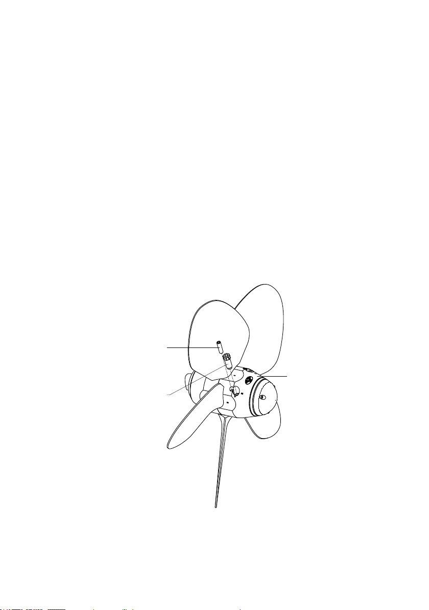
d) Orientate le pale nella loro posizione di bandiera (cioè
perfettamente allineate con l’asse del corpo
dell’elica), facendo attenzione che il loro profilo sia
come quello mostrato in fig. 2.
e) Prima di varare la barca è indispensabile effettuare le
seguenti operazioni:
•Bloccare l’albero motore.
•Verificare che le pale dell’elica ruotino liberamente
dalla posizione di marcia avanti a quella di marcia
indietro con la semplice spinta delle mani; a fine
corsa il loro angolo di inclinazione deve essere quello
prescelto.
•In posizione di bandiera le pale devono essere
perfettamente allineate ed orientate come in fig. 2
•Verificare che l’elica sia piena di grasso marino fluido
•Assicurare la protezione dell’elica contro la
corrosione galvanica applicando gli apposite anodi di
zinco sull’elica e sull’asse motore.
REGOLAZIONE DEL PASSO
Il passo della MAX PROP® EASY dipende dal diametro
dell’elica e dall’angolo αdi inclinazione delle pale. Nella
tabella di f ig. 3 sono riportati per alcuni diametri, i
passi in millimetri corrispondenti alle diverse angolazioni
delle pale
Diametro dell’Elica (millimetri)
300
350
400
450
500
550
600
650
700
750
800
αAngolo di inclinazione pale (gradi)
10°
100
115
130 150 170
185
200
215
230 250
265
12°
120
140
160 180 200
220
240
260
280 300
320
14°
140
165
190 210 235
260
280
305
330 350
375
16°
160
190
215 245 270
300
325
350
380 405
430
18°
180
215
245 275 305
335
365
400
430 460
490
20°
205
240
275 310 345
375
410
445
480 515
550
22°
230
265
305 340 380
420
455
495
535 570
610
24°
250
295
335 375 420
460
505
554
585 630
670
26°
275
320
370 415 460
505
550
590
645 690
735
28°
300
350
400 450 500
550
600
650
700 750
800
30°
325
380
435 490 545
600
655
705
760 815
870
Fig. 3
Fig. 1
Fig. 2
Fig. 3
PITCH ADJUSTMENT
The pitch of MAX PROP® WHISPER depends on the propeller diameter and the blade
angle α. Table in gure 3 shows, for some diameters, the pitches in millimeters
corresponding to different blade angles.
The diameter and pitch must be calculated as if MAX PROP®WHISPER was a common
xed-pitch propeller. With respect to traditional propellers, MAX PROP®WHISPER gives
the further advantage of allowing the pitch to be optimized if the performance is not
completely satisfactory. If the engine encounters difculties in reaching the operating
number of revolutions, then the blade angle α must be decreased; if, on the contrary,
the operating number of revolutions is exceeded, then the angle α must be increased.
By 2 degrees variation of the angle the boat speed varies by about 14% at the same
number of revolutions of the engine, or the number of revolutions of the engine varies
by about 14% at the same speed of the boat.
TO VARY THE PITCH, ACT AS FOLLOWS BY REFERING TO FIG. 3 AND 4
a. On the body of each propeller two threaded holes (housings) are obtained, marked
with letters “R” and “L”; a screw/rod is inserted in each hole. The pitch of the
propeller, for both forward and backwards motions, can be easily varied by changing
how deeply each screw/rod penetrate the body. If the propeller is right-handed,
the forward motion pitch can be changed by acting on the screw/rod housed in the

5
Fig. 4
hole “R” and the backwards motion pitch by acting on the screw/rod housed in
the hole “L”. On the contrary, if the propeller is left-handed the two pitches, for
forward motion and for backwards motion, are changed by acting on the screws/
rods housed in the holes “L” and “R”, respectively. Please note that the forward
motion pitch increases by increasing the penetration depth of the screw/rod in
the propeller body, and vice versa decreases by decreasing the depth. By contrast,
the backwards motion pitch increases if the penetration depth of the screw/rod is
reduced and vice versa.
b. A series of equidistant grooves are carved in the head of each screw/rod. These
grooves have dual capacity: locking the screw/rod in the selected position by
fastening it with a threaded grub screw, and precisely dening the value of the
rotation angle of the screw/rod, when switching from fastening in a groove to
fastening in the next groove. All the propellers have been sized so that, by one
complete turn of the screw/rod, the corresponding pitch of the propeller varies by
four degrees. Therefore, since there are eight grooves in the head of each screw/
rod, by shifting the locking of the screw/rod from one groove to the next (i.e. by a
single groove), the propeller pitch will vary by half a degree.
c. Each screw/rod is provided with a precise calibrated length. When the screw/rod
is completely screwed into its housing until it reaches the abutment (i.e. until
reaching its maximum penetration depth in the propeller body), the propeller
pitch, expressed in degrees, will correspond to the one shown in Fig. 5.
GRANO DI BLOCCAGGIO
LOCKING PITCH
ADJUSTMENT SCREW
VITE/ASTA DI REGOLAZIONE
PITCH ADJUSTMENT
SCREW/ROD
ELICA - PROPELLER

6
d. The penetration depth of the screw/rod in the propeller body, and therefore the
propeller pitch, can be easily varied by the user by choosing one of the following
two procedures, at will:
• PROCEDURE A:
Before installing the propeller on the boat, at rst insert into the two housings
two screws/rods each having great length and then screw them up to abutment.
In this way, the propeller will take two very precise pitches: a high pitch to travel
forward and a small pitch to travel backwards. These pitches will correspond
to those stamped on the two respective screws/rods. In order to change said
pitches, each screw/rod must be unscrewed by rotating it counterclockwise
by a specic angle (i.e., a precise number of grooves), thereby reducing the
respective penetration depths in the propeller body. Therefore, the propeller
forward motion pitch will decrease while the backwards motion pitch will
increases. Each of the two propeller pitches (to travel forward and backwards)
will vary according to the number of grooves between the new locking position
of the screw/rod and the previous abutment position thereof.
If the user wants to know the value of the pitch set on his propeller, he should
remember that the number stamped on the screw/rod (see g. 5) refers to the
propeller pitch in degrees reached when said screw/rod is completely screwed
up to abutment. Therefore, to satisfy the mentioned curiosity of the user, the
screw/rod has to be screwed while counting the number of grooves it rotates
to come into abutment (and therefore how many degrees the propeller pitch
has changed, remembering that the rotation between a groove and the next
one corresponds to a variation of the pitch of 0.5 degrees). If the screw/rod
is the one intended to adjust the forward motion pitch, the above variation
must be detracted from the value of the pitch stamped on such screw/rod. On
the contrary, in case in which the screw/rod is the one intended to adjust the
backwards motion pitch, the variation must be added.
• PROCEDURE B:
Check that the screw/rod already inserted in its housing had been screwed up
to the abutment. Then remove this rst screw/rod (corresponding to the rst
pitch) from the propeller body and screw up to abutment, in the same housing,
a second screw/rod having length different from the rst one. The new propeller
pitch will be the one stamped on the second screw/rod.

7
STAMPONTHE
SCREW/ROD
RANGEOF
REGULATION(PITCH
INDEGREES)
STAMPONTHE
SCREW/ROD
RANGEOF
REGULATION(PITCH
INDEGREES)
24
24°
23,5°
23°
…
…
12,5°
12°
1
16°
16,5°
17°
…
…
27,5°
28°
STAMPONTHE
SCREW/ROD
RANGEOF
REGULATION(PITCH
INDEGREES)
STAMPONTHE
SCREW/ROD
RANGEOF
REGULATION(PITCH
INDEGREES)
STAMPONTHE
SCREW/ROD
RANGEOF
REGULATION(PITCH
INDEGREES)
STAMPONTHE
SCREW/ROD
RANGEOF
REGULATION(PITCH
INDEGREES)
24 24°
22 22°
20 20°
18 18°
16 16°
MIXED
PROCEDURE
"A+B"
OPTIONALSUPPLY
CUSTOMERCAN
ASKTHESCREWS
HEPREFERS
ONLYTWO
SCREWSARE
FREEOFCHARGE
PROCEDURE
"B"
OPTIONALSUPPLY
CUSTOMERCAN
ASKTHESCREWS
HEPREFERS
ONLYTWO
SCREWSARE
FREEOFCHARGE
24°
16°
22°
24° 1
2
1
16°
16,5°
17°
…
…
27,5°
28°
16°
16
18°
18
20°
20
22
3
20°
FIG.5
SCREWS/RODSSUPPLIED
FORFORWARD
SCREWS/RODSSUPPLIED
FORREVERSE
PROCEDURE
"A"
STANDARDSUPPLY
FREEOFCHARGE
IFCUSTOMER
DOESNOTHAVE
ANYSPECIALREQUEST
24
SCREW/ROD KIT SUPPLIED FOR PITCH ADJUSTMENT
Fig. 5

8
• PROCEDURE A:
This procedure is the normally followed. Each MAX PROP®WHISPER propeller
is supplied with two screws/rod. The rst screw/rod, with the 24 degree pitch
stamped, is inserted into the housing intended to adjust the forward motion.
The second screw/rod, with the number 1 stamped, is inserted into the housing
intended to adjust the backwards motion. Eight grooves are carved into the
heads of each of the two screws/rods. By following the procedure A the user
can adjust, by half-degree intervals, both the forward motion pitch and the
backwards motion pitch. For convenience, in the head of each screw/rod also
four equidistant holes have been made (see g. 6). By moving the screw/rod
locking from one hole to the next one (i.e., by only one hole), the propeller pitch
will vary by one degree. The adjustment range is standard, that is: maximum
pitch 24 degrees for the forward motion and minimum pitch 16 degrees for
the backwards motion. In order to obtain pitches whose values are outside the
adjustment range, Max Prop can supply longer screws, on request.
• PROCEDURE B:
If this procedure is chosen, each MAX PROP®WHISPER propeller is supplied with
several screws of various lengths (on request), each length corresponds to a given
forward motion pitch and to a given backwards motion pitch.
• MIXED PROCEDURE A + B
Fig. 6
INSTRUCTIONS TO CHANGE DIRECTION TO PROPELLER ROTATION
MAX PROP® WHISPER gives the possibility to change direction of rotation, for example
if you change engine or in case of a mere error when ordering (If you have any doubts:
to understand the direction of rotation of your drive shaft, put into forward gear and

9
Fig. 7
look from stern to stem. If the shaft rotates clockwise, the rotation is right-handed;
by contrast, if it rotates counterclockwise, the rotation is left-handed). In order to
change rotation of the MAX PROP® WHISPER, from right-hand rotation to left-hand
rotation or vice versa, operate as follows referring to g. 7.
• Unscrew the screws locking the zinc, and remove the zinc.
• Unscrew the screws locking the nut, and remove the nut.
• At the aft edge of the hub there is a Seeger ring: remove it.
• Remove the transmission ring on which the zinc is xed (zinc-holding ring).
• Once the zinc-holding ring has been pulled out, you can see there is an engraving on
one tooth of the hub (aft side), and two teeth of the zinc-holding ring are marked
with “L” (left) and “R” (Right), respectively.
• If you reassemble the zinc-holding ring, placing the tooth “R” at the tooth of the hub
where the engraving is stamped, you will have a right-hand propeller, if you rather insert
the ring placing the tooth “L” at the tooth of the hub where the engraving is stamped,
you will have a left-hand propeller (see g. 7).
• Insert the Seeger ring in its seat.
• Screw the nut and lock it with the nut-locking screws.
• Put back the zinc, and fasten it with the three special screws.
BULINO DI RIFERIMENTO
REFERENCE MARK
VITI DADO
NUT SCREWS
ZINCO
ZINC
DADO - NUT
SECURITY RING “SEEGER”
ANELLO DI SICUREZZA “SEEGER”
ANELLO TRASMISSIONE MOTO e ANELLO PORTA ZINCO
TRASMISSION MOVEMENT RING and ZINC-BEARING RING
MOZZO
HUB
VITI ZINCO - ZINC SCREWS
B

10
PROPELLER USE
The MAX PROP®WHISPER propeller works completely automatically. It takes the pitch
when the drive shaft is rotated to travel forward or backwards (WARNING: reversing
the rotation when the number of revolutions is too high is denitely inadvisable). The
propeller feathers when engine is off, starting from the position to travel forward,
with the propeller shaft locked.
In order to feather the propeller, operate as follows:
• Drive the boat to travel forward.
• Turn off the engine without disengaging the forward gear, and lock the drive shaft.
DO NOT turn off the engine while traveling backwards, as in this case the blades will
be in the backwards motion position and will not feather. You can actually use this
method to rotate the shaft when the latter is connected to a generator.
IMPORTANT WARNINGS
Carefully follow the following instructions:
• Before reversing motion, allow the decrease of the number of revolutions of the
engine, and then reverse.
• Verify that the propeller body is full of very uid marine grease.
• The backwards motion must always be engaged starting from the forward motion
position, and through the neutral position, to avoid the thrust direction of the
propeller to be reversed.
• Protect the propeller against galvanic corrosion by applying a sufcient mass of zinc.
Replace the zinc anodes every year even if they have not corroded and check that
there is good electrical contact between the zinc, the propeller and the shaft (the
contact surfaces between the zinc and the bronze must be cleaned with abrasive
cloth).

11
PROPELLER DISASSEMBLY
In order to remove the propeller you must rst remove the zinc and the nut-locking
screws; then fasten a perforated washer, supplied only on request, on the zinc-holding
ring by means of ve threaded grub screws (g. 8). Screw the ve threaded grub screws
(long enough and provided with ve nuts) into the ve threaded holes obtained in the
zinc-holding ring, making sure that all ve threaded grub screws are tightened to the
bottom of their own threaded hole. Then lean all ve nuts on the perforated disc which
acts as extractor (see g. 8). Start unscrewing very smoothly the propeller-locking nut,
which will press against the washer (g. 8) and check that all ve extraction screws
work together with the same load to extract the propeller. Slowly unscrew the nut
and be careful not to overload the screws to prevent them from breaking. When, due
to nut unscrewing, stress is applied to all 5 screws, it may be helpful to knock lightly
on the propeller body with a plastic mallet. Said knocks will detach the propeller hub
from the propeller shaft.
Fig. 8
Spare parts reference code

MAX PROP®GENERAL SALE CONDITIONS
1. All the components of each propeller must not be modied in any way or for any reason.
2. All the components of each propeller are not interchangeable between a propeller and the
other.
3. The propeller must be used following the instructions of the manual enclosed with the prop,
paying particular attention to the warnings.
4. The non-compliance of the conditions 1, 2 and 3 means the loss of the warranty.
5. Max Prop Srl is to repair and replace free of charge the original pieces of the propeller which
may result damaged due to construction defects or due to material defects. Max Prop Srl
will not pay, for any reasons, any refund whatsoever, not even partial. The warranty granted
by Max Prop Srl is therefore limited exclusively to the repair or replacement of any possible
defective propeller and does not include any damage compensation refund, or claim of any
kind.
6. The reparations in warranty, that might be needed, will be carried on exclusively by Max Prop
Srl at its own workshop in Italy - Milan – Via Bernardino Galliari, 1. The customer will, at his
own charge and care, send the defective pieces to our workshop.
7. This warranty is valid 12 months starting from the date of propeller delivery.
8. Any possible controversy will fall within the jurisdiction of the Milan Courts-Italy.
9. The transport cost charged in the invoice from Max Prop doesn’t include any insurance. The
costumer notes that the insurance (even if pre paid from Max Prop), from the order conrm
and from the payment of the proforma, is not included on the transport. In case the customer
wants to insure the shipment, he will have to get in touch directly with the transporter and
agree an upgrade of the shipment charge with an insurance cover policy. In no way Max Prop
Srl can be considered responsible for any loss, damage or delay starting from when the goods
are given to the courier. The costumer itself must be considered responsible for any loss ,
damage or delay due to the transport, in case he has chosen not to stipulate a transport
insurance with the courier.
10. These conditions of sale are integral part of any purchase contract agreed with Max Prop Srl.
11. The ofcial and binding text of these general sale conditions is the one edited in Italian, any
translations in other languages are a form of courtesy. It is estabilished that the Italian text
will be the only value text.
12. The customer conrms that the purchase price of the propeller has been established
considering his acceptance of the present general conditions of sale. With this acceptance
the customer excludes any type of claim.
manufactured by: MAX PROP ®
via Bernardino Galliari, 1 - 20156 Milano - ITALY
tel. +39 02 33 404 325 - skype: maxprop1
Other manuals for WHISPER 5 BLADES
1
Table of contents
Other MAX PROP Marine Equipment manuals