ShipModul MiniPlex-2Wi User manual

MiniPlex-2Wi NMEA 0183 multiplexer
Manual
ShipModul
Marine Electronics
MiniPlex-2Wi, V1.0
Firmware V3.17.x
Art.no.: 1125
Man. rev. A
© CustomWare, 2012

2
Introduction....................................................................................................................... 3!
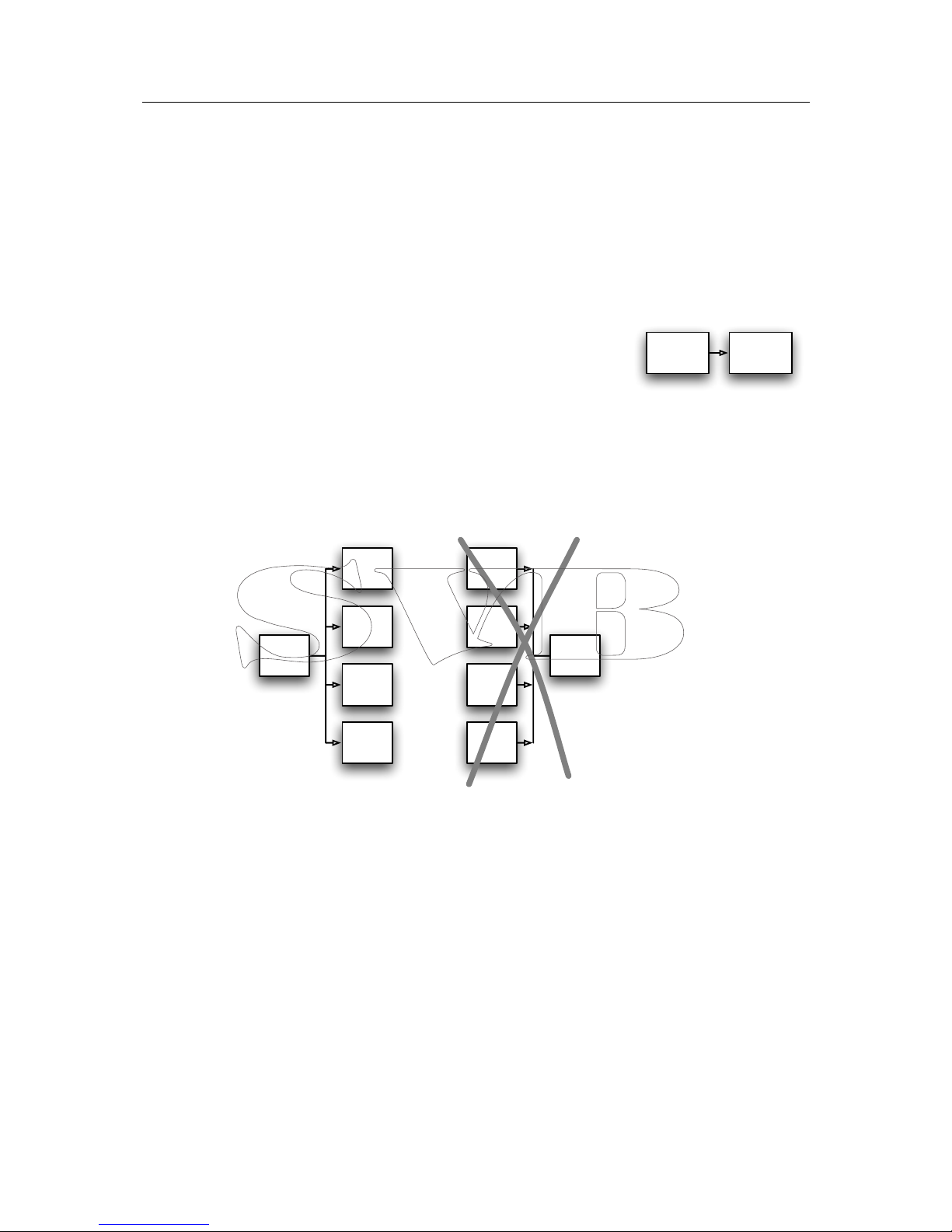
Talkers and Listeners ....................................................................................................... 3!
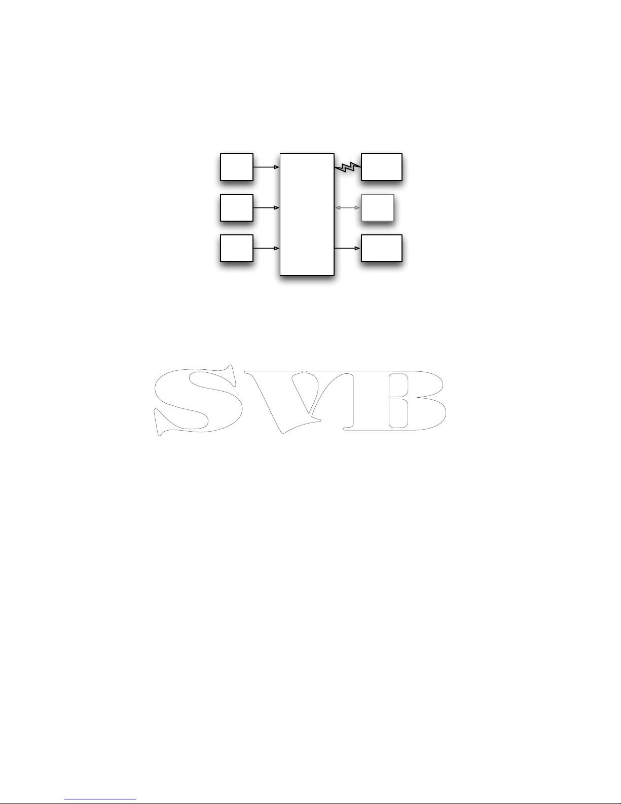
The Multiplexer................................................................................................................ 3!
The MiniPlex-2Wi ............................................................................................................. 4!
Connections....................................................................................................................... 5!
NMEA Signals .................................................................................................................. 5!
NMEA Listener Ports/Inputs............................................................................................... 5!
NMEA Talker Ports/Outputs ............................................................................................... 5!
Combining Ports .............................................................................................................. 6!
SeaTalk .......................................................................................................................... 7!
USB Port ........................................................................................................................ 7!
WiFi Interface.................................................................................................................. 8!
Power Supply .................................................................................................................. 8!
Indicators.......................................................................................................................... 8!
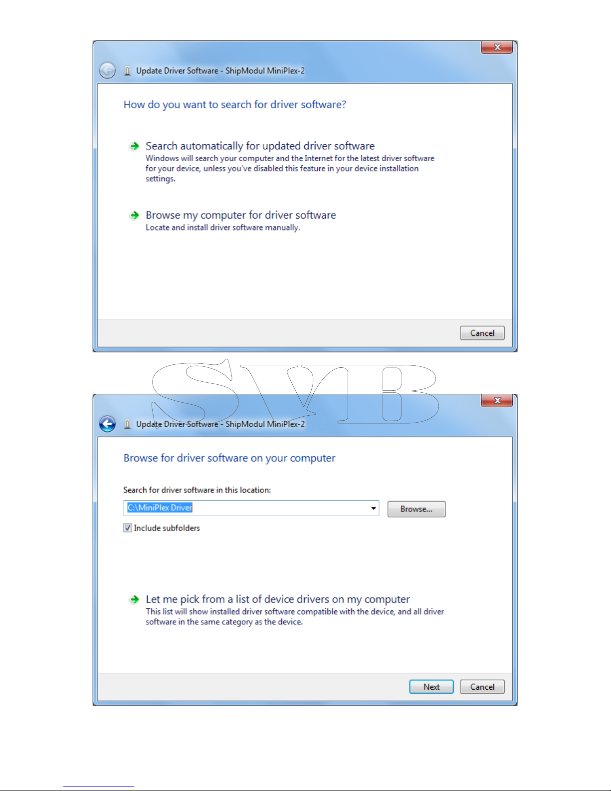
Driver Installation............................................................................................................... 9!
Windows 7 Installation ..................................................................................................... 9!
Windows 2000/Vista/XP Installation ................................................................................. 14!
Mac OS X Installation ..................................................................................................... 14!
Data Throughput .............................................................................................................. 15!
Configuration ................................................................................................................... 17!
Menu ........................................................................................................................... 18!
Controls ....................................................................................................................... 19!
Host Settings.............................................................................................................. 19!
Manual NMEA input ..................................................................................................... 19!
Input Overflow ........................................................................................................... 19!
Read Configuration...................................................................................................... 20!
NMEA Inputs/Outputs .................................................................................................. 20!
Options...................................................................................................................... 22!
NMEA Conversions. ..................................................................................................... 23!
Sentence Filtering & Routing ........................................................................................... 25!
Resetting the multiplexer................................................................................................ 27!
Firmware Update .............................................................................................................. 28!
Mounting......................................................................................................................... 28!
Technical Reference .......................................................................................................... 29!
NMEA Glossary .............................................................................................................. 29!
Talker ID’s ................................................................................................................. 29!
Sentence formatters.................................................................................................... 29!
Translated SeaTalk datagrams......................................................................................... 31!
Firmware Update Error messages..................................................................................... 32!
MPX-Config INI file format .............................................................................................. 33!
Proprietary NMEA Sentences ........................................................................................... 34!
CF – Configuration ...................................................................................................... 34!
CFQ – Request current configuration.............................................................................. 35!
CN - Channel Number indicator ..................................................................................... 35!
DR – Default Route ..................................................................................................... 35!
DRQ – Request Default Route ....................................................................................... 36!
FL – Filter .................................................................................................................. 36!
FLQ – Request Filter List .............................................................................................. 37!
ID – Talker ID ............................................................................................................ 37!
IDQ – Request Talker ID’s............................................................................................ 37!
LDR – Loader message ................................................................................................ 37!
OV – Overflow ............................................................................................................ 37!
RESET – Reset the multiplexer...................................................................................... 38!
SP – Speed ................................................................................................................ 38!
SPQ – Request Speed .................................................................................................. 38!
TAG Block .................................................................................................................. 38!
VER – Get Version....................................................................................................... 39!
WI – Wireless control................................................................................................... 39!
Technical Specifications .................................................................................................. 42!
Declaration of Conformity .................................................................................................. 43!

3
Introduction
The MiniPlex-2Wi is an NMEA multiplexer that enables the connection of multiple NMEA 0183
instruments to each other and a computer and/or wireless devices. It is developed to solve a
fundamental problem with the NMEA 0183 standard.
The NMEA 0183 standard defines a communication protocol that enables navigation instruments to
exchange data with each other. A compass can send a bearing to a radar to enable a north-up
display, a GPS can send cross-track information to an autopilot in order to steer a programmed
course. The same GPS can also send information to the radar at the same time since the NMEA
0183 standard specifies that one device must be able to send data to up to four other devices.
NMEA data is made up of short text messages with a strict format called sentences and are human-
readable.
Talkers and Listeners
Communication using the NMEA 0183 protocol involves at least one
device that sends NMEA sentences and another device that receives
NMEA sentences. By convention, a sending device is called a talker
while a receiving device is called a listener. The picture on the right
shows such a minimal system: a gyrocompass sending heading
sentences to a radar.
The NMEA 0183 standard specifies that a talker should have enough driving capability to talk to
four listeners. This is as easy to achieve as telling a story to an audience of up to four people. The
only requirement is to talk loud enough.
The picture left below shows such a situation.
It gets complicated when several talkers must send data to one listener as shown in the picture on
the right. Unless that listener has multiple inputs, this is not possible without help. Simply
connecting talkers to one listener as shown is like four persons simultaneously telling you a
different story. You can make neither head nor tail of it. In electronics terms: the outputs of the
talkers will effectively short-circuit each other and the sentences they transmit will be corrupted.
This is where a multiplexer offers the solution.
The Multiplexer
A multiplexer, sometimes called ‘combiner’, has multiple inputs, each acting as a single listener
connected to a talker (the instruments). It has one or more outputs that are able to talk to multiple
listeners. These outputs deliver the combined data from the inputs.
A clever piece of software inside the multiplexer reads the NMEA sentences that are received on
the inputs simultaneously and stores them into queues, one for each input. Another part of the
software retrieves the sentences from the queues, one at a time, and sends them to the outputs of
the multiplexer. This way, four incoming streams of sentences are combined into one single
stream.
GPS
PC
VHF
Radar
Auto-
pilot
PC
GPS
Depth
Wind
Log
Gyro Radar

4
The picture below shows a typical setup with a multiplexer combining data from a wind instrument,
a compass and a GPS. This data is forwarded to a tablet and an autopilot using two different types
of outputs: an NMEA talker port called ‘Out1’ and a WiFi interface. The multiplexer forwards the
received NMEA sentences to the tablet and the autopilot at the same time.
The WiFi connection to the tablet is actually bi-directional: the tablet acts as a listener and a talker
at the same time. It receives NMEA sentences from the instruments to be processed by navigation
software on the tablet. This software can generate NMEA sentences to control an autopilot. These
sentences are sent to the multiplexer and forwarded to the autopilot. They can be combined with
the sentences received from the other navigation instruments.
The picture also shows a computer in light grey that is connected to the USB port on the
multiplexer. The MiniPlex-2Wi also has a USB port with the same function as the WiFi interface.
This allows you to connect a second (fixed) computer while having the freedom of moving around
with your laptop, PDA, tablet or smartphone having access to the same navigation data as the
fixed computer.
The USB port is also used to update the firmware of the multiplexer and to configure the WiFi
interface. These tasks cannot be performed using the WiFi interface.
The MiniPlex-2Wi
The MiniPlex-2Wi is a multiplexer with four NMEA inputs (listener-ports), two NMEA outputs (talker-
ports), a WiFi interface and a USB port to connect to a computer. The multiplexer combines NMEA
data that is received on the listener ports In1 to In4 and sends this data to talker ports Out1 and
Out2,to the WiFi interface and to the USB port. The WiFi interface and the USB port are also used
to send data from a computer to the multiplexer to be forwarded to Out1, as well as to send
commands to configure the multiplexer.
Every NMEA input on the MiniPlex is galvanically isolated, sometimes called opto-isolation because
of the use of opto-couplers for isolation. An opto-coupler is a small device that transports
information by means of light instead of electricity.
A galvanically isolated input prevents unwanted currents to flow between instruments and the
multiplexer. These currents can damage equipment or interfere with radio signals and should
therefore be avoided. Galvanically isolated inputs are required by the NMEA standard.
The USB port of the MiniPlex is also galvanically isolated, which isolates the computer from the
navigation network and protects it against potential damage caused by ground loops or voltage
spikes.
Both NMEA outputs can drive up to four listeners each. Flexible routing options allow you to specify
which NMEA sentences are sent to these outputs.
Besides the basic functionality of combining NMEA data from multiple sources, the MiniPlex offers a
range of features to manage NMEA data like Sentence Filtering and Routing, Input Priority with
automatic switchover, testing of data integrity, Talker ID modification and SeaTalk®to NMEA
translation.
The MiniPlex can seamlessly be integrated into an existing Raymarine SeaTalk network when
SeaTalk mode is enabled. This mode changes one NMEA listener port into a SeaTalk input. When
connected to a Raymarine SeaTalk network, the multiplexer will translate SeaTalk data into NMEA
sentences and combine these with NMEA sentences that are received on the other listener ports.
Only one SeaTalk input is needed since the SeaTalk bus is a single-cable system that connects all
instruments together through one single cable. SeaTalk to NMEA translation in the MiniPlex works
only one-way. No NMEA sentences are converted into SeaTalk, the multiplexer just listens on the
SeaTalk bus.
Wind
Comp-
pass
GPS Autopilot
Multiplexer
In 1
In 2
In 3
USB
Out 1
PC
Tablet
Wifi

5
Connections
NMEA Signals
Although the NMEA 0183 standard very clearly specifies the signal names, voltage levels and
connection methods, the reality is far from this ideal world.
The most important property of an NMEA port is that the connections or wires are labelled ‘A’ and
‘B’ and that it uses a differential signalling scheme. This means that data is transmitted on both
wires, but in ‘opposite direction’. Both wires are driven between 5V and 0V and opposite of each
other. This means when A is 5V, then B is 0V and vice versa. The advantage of this signalling
scheme is that it is very insensitive to electrical interference. NMEA ‘A’ and ‘B’ are often labelled as
NMEA ‘+’ and ‘-’ respectively. When connecting devices, simply connect NMEA ‘A’ to NMEA ‘A’ or
NMEA ‘+’ and NMEA ‘B’ to NMEA ‘B’ or NMEA ‘-’.
Things get complicated when manufacturers don’t follow the NMEA 0183 standard, which is very
often the case. Many devices have an NMEA port, which is really an RS-232 port. The only
resemblance with the NMEA standard is the format of the data transmitted. Electrically, they are an
entirely different world. The used signal names differ wildly and often lead to confusion. When a
device has a listener port with connections ‘Data In’ and ‘Data Return’ it is not clear whether this
input is galvanically isolated or ‘Data Return’ is simply another name for ‘Signal ground’
As opposed to the NMEA standard, many devices use a single-ended signalling scheme where data
is transmitted on one signal wire while a power/signal ground presents the return path for data.
Single ended devices often have connections named as TX and Gnd (transmit and ground) on the
talker port and RX and Gnd (receive and ground) on the listener port. Also used are Data Out, Data
In and Signal Ground. Mix these with ‘standard’ NMEA connections and confusion is imminent!
In general it is safe to connect a single ended talker port to a differential listener port. Connecting
a differential talker port to a single ended listener port however is less obvious. When NMEA ‘B’ of a
talker port is connected to the signal ground of a listener port, the ‘B’ signal is effectively short-
circuited to ground. A properly designed talker port can handle this abuse but it will result in fairly
high currents in long cables, which in turn leads to severe interference on SSB radios and possibly
on VHF radios too. In the worst case, the talker port will be destroyed.
To overcome this problem, the MiniPlex multiplexers provide a Com terminal on each talker port in
addition to the ‘A’ and ‘B’ terminals. This ‘Com’ terminal is similar to a signal ground. To connect a
talker port of the MiniPlex to a differential NMEA listener port, use the ‘A’ and ‘B’ terminals. Use the
‘A’ and ‘Com’ terminals to connect to a single-ended or RS-232 listener port.
NMEA Listener Ports/Inputs
The multiplexer has four listener ports or inputs, In 1 to In 4. Each listener port should be
connected to one instrument only. These inputs are completely floating and galvanically isolated
from the multiplexer, as specified in the NMEA 0183 standard.
Connect the Aand Bterminals of the listener port on the multiplexer to the Aand Bterminals of
the talker port on the instrument. These terminals may also be labelled as Data+ and Data-, TX+
and TX-, Out+ and Out–or ve+ and ve-.
Some instruments have single ended talker ports, with only one data terminal. Connect this
terminal to the Aterminal on the multiplexer, and connect the ground of the instrument to the B
terminal on the multiplexer. The instrument’s data ground is often combined with its power supply
ground.
NMEA Talker Ports/Outputs
Both talker ports or outputs can be connected to up to four instruments. Connect the Aand B
terminals of the talker port on the multiplexer to the Aand Bterminals of the listener port(s) on
the instrument(s). These terminals may also be labelled as Data+ and Data-, RX+ and RX-,
Out+ and Out–or ve+ and ve-.
Multiplexer
In A
In B
Instrument
Out A/+
Out B/-
Differential
Multiplexer
In A
In B
Instrument
TX/Out
Ground
Single ended

6
Some instruments have single ended listener ports, with only one data terminal. Connect this
terminal to the Aterminal on the multiplexer, and leave the Bterminal on the multiplexer
unconnected. Connect the ground of the instrument to the Com terminal on the multiplexer. The
instrument’s data ground is often combined with its power supply ground.
The shield terminals on the multiplexer (Shld) can be connected to the screen/shield of the cable if
available. This should always be done on one end of the cable only, preferably on the end that is
connected to a talker port.
Combining Ports
It is sometimes necessary to combine a listener and talker port of the multiplexer to connect to an
instrument. One of the most commonly used combinations is the connection of a GPS to the
multiplexer. While some GPS receivers have properly designed NMEA ports, many only have an
RS-232 port which is single ended with three terminals: TxD (data out), RxD (data in) and Ground.
The picture below shows how to connect such a GPS to the multiplexer.
Instrument
In A/+
In B/-
Multiplexer
Out A
Out B
Differential
Instrument
RX/In
Ground
Single ended
Com
Multiplexer
Out A
Out B
Com
Instrument
In A/+
In B/-
Multiplexer
Out A
Out B
Multiple differential and
single ended listeners
Com
Instrument
In A/+
In B/-
Instrument
RX/In
Ground
GPS
TxD/Out
Ground
RxD/In
Multiplexer
In A
In B
Out A
Out B
Com
Connecting a GPS with a serial port
to the multiplexer

7
SeaTalk
SeaTalk®is a proprietary protocol developed by Raymarine®. This protocol is used for
communication between Raymarine navigation instruments like the ST40, ST50 and ST60 series.
To be able to use these instruments with commonly available navigation programs or to feed their
data into other non-Raymarine instruments, the SeaTalk data needs to be translated into NMEA.
Even Raymarine's own navigation software, Raytech Navigator, needs this translation.
The MiniPlex can be directly connected to a SeaTalk network. It will translate all SeaTalk data
required for navigation into NMEA sentences. Input In 4 can be set to SeaTalk mode
(SeaTalk -> NMEA) and should be connected as shown below:
Note that the red and yellow wires are used! The shield of the SeaTalk cable is not connected to
the multiplexer.
USB Port
The USB port connects the multiplexer to a computer or a USB hub with the supplied cable. The
supplied driver provides a virtual COM port to allow navigation software to communicate with the
multiplexer. The USB port is bi-directional: the multiplexer sends NMEA data to the computer and
the computer can also send NMEA data back to the multiplexer. This data can be routed to
NMEA Out 1 and NMEA Out2.
The USB port is galvanically isolated from the multiplexer to prevent ground loops and excessive
currents that could otherwise destroy the multiplexer or the USB port of the connected computer.
The USB connection supports flow control, which is needed when waypoints and routes are sent
from the computer to a GPS through the multiplexer. While normal NMEA sentences are sent at
regular intervals, waypoints and routes are sent ‘in one go’ without any pause between these NMEA
sentences. This fills up the queue in the multiplexer almost immediately after which the multiplexer
discards the remaining waypoints and routes. The GPS now only receives a few waypoints and
partial routes.
Flow control prevents this from happening. When the queue in the multiplexer is almost filled, the
multiplexer signals the computer to stop sending data. When the queue is sufficiently emptied, the
multiplexer signals the computer to continue. This requires a special setting in your navigation
software, which is mostly called ‘Flow Control’. This setting can mostly be found in the port settings
of your software. Set the Flow Control to Hardware or CTS/RTS. This Hardware flow control is
virtualized over the USB connection. Do not use Xon/Xoff flow controls since this uses special
characters instead of a (virtual) signal. These characters are not part of the NMEA standard and
therefore ignored by the multiplexer.
SeaTalk cable
Multiplexer
In 4A
In 4B
Red
Yellow
Connection to a SeaTalk network

8
WiFi Interface
Through its WiFi interface, the MiniPlex-2Wi can communicate with a wireless device such as an
iPad, iPhone, an Android based smartphone or tablet, a PC or a Mac. The multiplexer creates a
wireless Access Point 820.11b+g interface with the following parameters:
SSID (name): MiniPlex-2Wi:xx:xx
IP address: 10.0.0.1
Port: 10110
Protocol: TCP
The xx:xx’s are the last two bytes of the MAC address of the multiplexer as printed on the serial
number sticker. This uniquely identifies a MiniPlex-2Wi from similar devices.
A wireless device that connects to the MiniPlex-2Wi will get an IP address from the built-in DHCP
server. It is not necessary to set a fixed IP address in your device.
Configure your navigation software to connect to IP address 10.0.0.1 and port 10110 using the TCP
protocol.
The MiniPlex-2Wi supports only one connection WiFi connection at a time. The WiFi interface and
the USB port operate simultaneously and with the same priority. This allows an on-board fixed
computer to be connected simultaneously with a wireless device.
The WiFi interface cannot be used to update the firmware of the MiniPlex-2Wi or to configure the
WiFi interface using $PSMDWI commands (see the Technical Reference, Proprietary NMEA
Commands). All this has to be done using the USB interface.
Power Supply
The multiplexer must be powered from an externally supplied DC voltage from 8 to 35V. The power
supply connection is protected against reversed polarity.
Indicators
The multiplexer has three LEDs. The green LED indicates the reception of valid NMEA data on the
listener ports or from the network. It only blinks on valid NMEA sentences that start with a ‘$’ or ‘!’
and end with a CR and LF character, thus indicating a proper connection and polarity of the
connected instrument. In case of a reverse polarity of a connected talker, the green LED will not
blink. The green LED also blinks every two seconds to indicate that power is present and it is
operational. This blink is slightly dimmer than a blink on data reception.
The red LED indicates a queue overflow, in case more data is received than can be transmitted.
See section ‘Data Throughput’ for options to resolve this situation.
During a firmware update, the red LED will be lit continuously when the update is in progress while
the green LED blinks on the reception of firmware data from the computer. This will give a visual
indication of the update process.
The yellow led indicates the status of the WiFi connection: and has three possible states:
Off: The MiniPlex is configured to connect to a WiFi Access Point but the connection failed.
On: The WiFi Access Point is active and ready for use.
Blinking: An application has connected using TCP.

9
Driver Installation
To use the MiniPlex-2Wi with your computer using the USB interface, a device driver needs to be
installed. This driver creates a virtual COM port, which can be opened with any navigation software
just like any other COM port. Drivers are supplied for Microsoft Windows (Windows 2000, Windows
XP, Windows Vista, Windows 7) and Apple’s Mac OS X.
If you plan to use the MiniPlex-2Wi using the WiFi interface only, no driver needs to be
installed. Firmware updates however can only be loaded using the USB interface.
Windows 7 Installation
When the MiniPlex is connected to the computer for the first time, Windows will automatically
download the most recent drivers from the Windows Update Service when an Internet connection is
available. Without connection to the Internet, Windows will eventually tell you that the ‘Device
Driver software was not successfully installed’.
The following procedure allows you to install the drivers for the MiniPlex manually.
Open Control Panel -> System and Security -> Device Manager.
In the Device Manager, there will be a ‘ShipModul MiniPlex-2Wi’ listed under ‘Other Devices’ as
shown in the picture.
Right-click on the MiniPlex entry and choose ‘Update Driver Software...’ from the menu that
appears. This will open the following window:

10
Choose ‘Browse my computer for driver software’. In the following window, choose the location of
the driver (the ‘\USB Driver\Windows’ subfolder on the MiniPlex Driver & Utility CD) and press
‘Next’.

11
When Windows has successfully installed the driver, the following window appears:
You can close this window.
The Device Manager will now list an USB Serial Port under Other Devices:

12
Right-click on the USB Serial Port entry and choose ‘Update Driver Software...’ from the menu that
appears. This will open the following Window:
Choose ‘Browse my computer for driver software’. In the following window, choose the location of
the driver (the same location as last time will be shown again) and press ‘Next’.

13
When Windows has successfully installed the driver, the following window appears:
You can close this window.
The Device Manager will now list a ShipModul MiniPlex NMEA Multiplexer under Universal Serial Bus
controllers and a MiniPlex Serial Port (COMx) under Ports (COM & LPT).

14
Windows 2000/Vista/XP Installation
When the multiplexer is connected to a USB port for the first time, Windows will detect new
hardware and prompts you for a driver. Insert the supplied CD into the drive and follow the
instructions on your screen. If you have an Internet connection, you can let Windows search the
Internet for updated drivers. Otherwise, when asked to automatically search for drivers, answer no
and choose the option to tell Windows where to find the driver. The driver can be found on the
supplied CD, in de folder ‘\USB Driver\Windows’
The installation on Windows is a two-step process. First, the driver for the multiplexer will be
installed. Next, Windows will detect a USB Serial device and will install a second driver. On
Windows XP systems, there can be a delay of up to 10 seconds between the installation of both
drivers, which sometimes leads to the conclusion that the installation is complete after the first
driver is installed which is not the case. On Windows Vista and Windows 2000 systems, there is
only very little delay.
When the installation is complete, a new virtual COM port will be created. This COM port is shown
in MPX-Config as COMx (vcp) where ‘x’ is a number. Select this port in your navigation software.
The ‘vcp’ extension as shown in MPX-Config will not be visible in your navigation software.
If necessary, the number of this COM port can be changed in the Windows Device Manager. Click
on the ‘+’ sign next to the entry marked as ‘Ports (COM & LPT)’. This will expand the entry to list
all available COM ports on your computer. The port for the multiplexer is listed as ‘MiniPlex Serial
Port (COMx)’ where ‘COMx’ is the name of the newly created serial port.
To change this port number, double click on the MiniPlex Serial Port (COMx) entry to open the
property page for this port. Next, select the Port Settings tab and click on the Advanced…
button. In the appearing window the used port number can be changed. Do not change any other
setting in this window.
It is possible to select a port number that is already present on the computer, like COM1. The
original COM1 port will then be disabled as long as the multiplexer is connected to the computer.
This feature allows the port number to be set in a low range from COM1 to COM4, to accommodate
software that only allows COM1 to COM4 to be selected.
More than one multiplexer can be connected at the same time. Every new unit will create a new
virtual COM port. The number of the COM port will always be assigned to the same multiplexer
regardless of the USB port being used.
Windows allows a maximum of 256 COM ports. However not all software may be able to select
COM ports numbered above COM9.
When installing updated drivers, uninstall the original drivers first with the
Add/Remove Programs icon in the Control Panel or use the Update Driver button on the
Driver page of the MiniPlex Serial Port property-page.
Mac OS X Installation
The OS X driver is available as a disk image file (.dmg) and can be found on the supplied CD in the
‘USB Driver’ folder. Run the installer by double clicking on the icon. Follow the instructions on the
screen. When the installation is complete, plug in the USB cable of the MiniPlex. The MiniPlex will
show up in the ports list of your navigation software as MiniPlex-xxxxxxxx where the xx’s represent
the serial number of the MiniPlex.

15
Data Throughput
Depending on the configuration of the multiplexer, NMEA sentences are sent to one or more
outputs with different communication speeds. A situation could arise where more data is received
than can be transmitted because of the different speed settings of the inputs and outputs. Such a
situation leads to an overflow of the input queues of the multiplexer. When an NMEA sentence is
being received while a queue is full, this sentence is discarded. Only complete NMEA sentences are
stored and forwarded. This event is indicated by the red LED, which will blink briefly when a
sentence is discarded and the indicators in the Input Overflow section on the MPX-Config screen.
In its default factory setting, as shown below, the data flow through the MiniPlex is very
straightforward. First of all, the data that is received on the NMEA inputs is always sent to the
computer via the host interface(s).
In addition to this, the same data is also routed to Out2, as indicated by the checkboxes in the
section Input Settings. The section Output Settings shows that data from the computer (Host)
is routed to Out1 only.
This basic configuration allows you to combine data from navigation instruments and send it to a
computer using the Host port(s) and to a chart plotter connected to Out2 while the computer can
control an autopilot connected to Out1.
The default speed setting of the inputs and outputs ensures that there will be no queue overflows.
Please note that the default communication speed of Out2 is 38400 baud. Most chart plotters
support this high speed for reception of AIS data. However, if you want to connect this output to a
repeater display or a VHF radio, the speed of Out2 must be lowered to 4800 baud. If this leads to
excessive overflows, it is necessary to reduce the amount of data sent to this output. This can be
achieved by changing the default routing settings (disable certain inputs for Out2) or by using the
Sentence Filtering & Routing facility of the MiniPlex.
Now back to data throughput. The standard speed of an NMEA port is 4800 Baud or bits/second,
representing 480 characters per second. It is quite obvious that when four inputs receive data at
480 char/s and all of this data must be sent out again on an output with the same bandwidth of
480 char/s, a huge problem will arise. In the default configuration this problem does nor occur
because the speed of Out2 is set to 38400 Baud (3840 char/s). When Out2 is not used, set it to
the highest speed or disable routing of any of the inputs to Out2. When Out2 is connected to a
chart plotter, try to choose the highest speed the plotter will accept.
If data from more than one input needs to be routed to an output operating at 4800 Baud,
problems with data throughput can arise when too much data is sent to this output.
NMEA data tends to be sent in bursts. Some devices line depth sounders or wind instruments only
send one sentence per second while a GPS may send bursts of up to 13 sentences every two
seconds. While the average throughput over time may be low, an input might fill its queue quite
rapidly when a burst of sentences is received. The queues in the MiniPlex are quite large and may
contain up to 30 sentences of GPS data.
A couple of occasional blinks of the red LED over a period of a few seconds means that large bursts
of sentences are received and a queue is hitting its limit. Some sentences are discarded but most
of them will be passed without problems. Such a situation is totally acceptable and would mean
that for instance one depth, wind or position update is missed every few seconds.

16
A quite different situation may arise with some fluxgates or gyrocompasses. These devices may
send their heading sentences with a speed up to 40 sentences per second! Instead of queuing a
burst of sentences every one or two seconds, the multiplexer must queue a constant stream of
sentences, possibly utilizing the maximum bandwidth of the multiplexer. Such a situation can lead
to a queue that is constantly filled up to its maximum capacity. This in turn results in heading data
that can be up to 20 seconds old when it is forwarded, which is totally unusable for any autopilot to
steer on. Enabling the Real Time option for this input can solve this specific problem. This option
bypasses the queue entirely. Only one sentence will be stored now and sent out when the time slot
for this input arrives. Outside its time slot, incoming sentences will be discarded. A lot of heading
sentences will be lost now but the ones that are passed, are passed almost immediately. Hence the
name ‘Real Time’.
When the red LED is blinking severely or stays on almost
continuously, it is advisable to investigate which instrument or
input leads to this overflow. The MPX-Config utility will show on
which input the overflow occurs by a blinking indicator in the
NMEA Input Settings section. Opening the Statistics window
from the Tools menu will give an insight about the amount of data
in a queue and whether it is filled constantly or occasionally.
Some general rules are applicable for reducing overflow situations.
A simple rule of thumb is that an overflow can never occur if the
speed of an output is equal or higher than the combined speeds of
all inputs that are routed to that output. For example: if the
multiplexer is in its default configuration and all four inputs are set
to 4800 Baud, the minimum output speed equals 4 x 4800 =
19200 Baud. This rule is only a hard rule when the input
bandwidth is fully utilized i.e. an instrument is sending data
continuously. This is hardly ever the case. As mentioned earlier,
NMEA data is often sent in bursts, resulting in a much lower overall
bandwidth. It could be perfectly feasible to have a system with
four instruments connected to the multiplexer, while running all in- and outputs on 4800 Baud
without a single overflow.
There are several ways to resolve overflow situations:
1. Configure the instruments on the listener ports to send less data or with greater intervals.
GPS receivers can sometimes be configured for this.
2. Use the sentence filter of the multiplexer to block unwanted sentences. Unwanted
sentences are discarded immediately and do not occupy queue space or bandwidth.
3. For sentences that should not be blocked, setting a divisor in the sentence filter may lower
their rate. A gyro may be ‘throttled down’ to 10 sentences per second or even less. From
the GPS output, the rate of the sentences containing satellite information could be lowered
to once every 10 seconds instead of being output every time a position is output by the
GPS.
4. Use the routing options to select which input is routed to an output or use the routing
options in the sentence filter to selectively route NMEA sentences to an output.
5. Increase the speed of the NMEA output that causes the bottleneck. This will only work
when the connected equipment also supports higher communication speeds.

17
Configuration
The multiplexer can be configured with a configuration program called MPX-Config. This program
can be found on the accompanying CD. There is no installation procedure for this program, just
start it from the CD or copy it to a suitable folder on the hard disk of your computer and start it
from there.
The multiplexer itself is configured with proprietary NMEA sentences. MPX-Config sends these
sentences to the multiplexer when you change a control on the screen.
All configuration settings are stored in the multiplexer’s non-volatile memory. These settings are
retained without power supply.
Screenshot of MPX-Config
The screen is divided into four sections from top to bottom: the menu, the data area, the control
area and the status bar. The menu basically controls the MPX-Config program. The data area
shows the NMEA sentences that are received from the multiplexer. These sentences include the
NMEA data received by the multiplexer on its inputs as well as status messages generated by the
multiplexer. The latter can be recognised fairly easy: they all start with ‘$PSMD’. The control area
contains controls that determine the operation and configuration of the multiplexer. The status bar
shows the name or type of multiplexer that is connected, its internal software (firmware) version
number and its serial number. This information is useful when you need technical support. Also
shown are the optionally loaded or saved configuration file and a line counter when you have
started a log file.

18
Menu
The menu contains two sub-menus: File and Tools. The File menu contains the following options
to choose from:
Start Log… Start writing NMEA data to a log file. A log file is a plain text file and
can later be opened by any text editor to examine the data. A log file
can be a useful tool for diagnostic purposes and is often requested by
us for support. If you enter a new filename in the file dialog window, a
new log file is created. If you choose an existing file, this file will be
overwritten with new data. The Log counter on the status bar will show
the number of NMEA sentences that are currently written to the log file.
Timed Log… Start writing to a log file with the addition of a time stamp at the
beginning of each NMEA sentence.
Stop Log Stop writing NMEA data to the current log file and close that file.
Load Configuration… Load a previously saved configuration file into the multiplexer. The
current configuration will be overwritten. A configuration file stores all
settings made with MPX-Config. See the Technical Reference section for
a description of this file format.
Save Configuration Save the current configuration to a file. If a file was previously opened,
that file will be overwritten. If no file has been opened before, you will
be prompted for a file name. The name of the currently loaded
configuration file is shown on the status bar.
Save Configuration As… Save the current configuration to a new file.
Update Firmware… Load new firmware into the multiplexer. From time to time, new
features are developed for the multiplexer or bugs are fixed. New
firmware image files will then be made available through our website.
These image files can be downloaded to your computer and loaded into
the multiplexer with this option. This option will only be visible when
your multiplexer supports firmware updates. This is the case from
firmware version 3.00 and up. Multiplexers containing lower firmware
versions need to be returned to our factory for an update.
Exit This option exits MPX-Config.
The Tools menu contains the following options to choose from:
Clear Screen Clear the data area on the screen. New sentences will be displayed
from the top.
No Scroll Normally, incoming NMEA sentences are displayed from the top down
and when the bottom of the data area has been reached, all sentences
are scrolled up one line before the new one is show. When No Scroll is
activated, a list of incoming NMEA sentences will be displayed that will
be refreshed constantly when new similar sentences are received. A
scroll bar will appear when the list grows beyond the length of the data
area. This feature allows you to closely examine the types of sentences
that are received from the connected instruments. Any proprietary
NMEA sentences that are generated by the multiplexer are also listed.
The can be recognised by the firsts four characters, which are ‘$PSMD’.
Show Statistics This option opens a new window that will be displayed on top of the
MPX-Config window. This window show bars that indicate how much
NMEA data is stored in the input queues. This is a useful option for
diagnosing data congestion and overflow situations as mentioned in
paragraph ‘Data Throughput’. A queue that is filled constantly can lead
to unacceptable delays in data transfer.
About Show a window with version information.

19
Controls
The control area of the MPX-Config screen allows you to configure the multiplexer. It is devided in
two parts: a small part on the left contains the Host Port settings, the Manual NMEA Sentence
Input, the overflow indicators and the Read
Configuration button. These items are available at all
time. The largest part on the right contains all settings that
control the operation of the multiplexer. These settings are
logically grouped on tabbed pages. When started for the
very first time, the NMEA Inputs/Outputs tab is shown. On
exit, MPX-Config stores the currently active tab and shows
this on the next startup.
Host Settings
Before being able to configure the multiplexer, select the
communication port to which the multiplexer is connected
in the Host Settings. These settings control the
communication settings of your computer or tablet, which
are called the Host. Nothing is changed in the multiplexer
here. Because there are several ways to connect a host to
the multiplexer, you will find a number of possible ‘ports’ in
the Port selector, ranging from available COM ports on your
computer to TCP and UDP.
Depending on the kind of selected port, the Host Settings
section changes its appearance. When you select a COM
port, the section shows a Speed selector to select the
communication speed of the COM port. When TCP or UDP is
selected, the section shows an entry field for an IP address.
In case of a virtual COM port (a COM port created by the USB driver of the MiniPlex), the COM port
is marked with ‘(vcp)’ and the Speed setting is irrelevant.
If you connect to the multiplexer using TCP, enter the IP
address of the multiplexer in the Host field as shown. The
IP address of the MiniPlex-2Wi is 10.0.0.1.
Once you have set the desired settings, click on the
Connect button to start the connection to the multiplexer.
When a virtual COM port has been selected, the Speed setting will change to Automatic and will
be disabled. MPX-Config will now retrieve the current settings from the multiplexer and enable the
tabbed configuration pages.
If a ‘Multiplexer does not respond’ – message appears, you may have selected the wrong COM
port. In case of a wrong IP address, an ‘Unable to connect’ –message appears.
If you exit MPX-Config, the port settings will be saved and reloaded on the next start-up of MPX-
Config.
When you select a different port while being connected, MPX-Config disconnects from the
multiplexer and you have to click on Connect again.
Manual NMEA input
MPX-Config allows manual entry of NMEA sentences for testing, configuration etc.
Type the desired NMEA sentence in the edit box and click on the Send button or press the enter
key. MPX-Config will keep a history of entered sentences/commands.
Preceding the NMEA sentence with a ‘$’ is optional, MPX-Config will add it if it is omitted. The input
is case sensitive, so whatever you type will be sent to the multiplexer literally. Since all NMEA
commands are uppercase, you have to enter them as uppercase.
Any sentence starting with ‘$PSMD’ will be recognized by the multiplexer as a configuration
command and will be processed as such. Any other sentence will be sent to the NMEA outputs.
Input Overflow
The overflow indicators show which input suffers from a queue overflow. See the section ‘Data
Throughput’ for ways to prevent overflow situations with different instruments.

20
Read Configuration
Clicking this button will retrieve the current configuration settings from the multiplexer. MPX-Config
will do this automatically when you click on the Connect button but it can be useful to re-read the
configuration at a later stage.
When the wrong port is selected, MPX-Config will show a ‘Multiplexer does not respond’ - message
and all controls will be disabled (greyed).
The status line on the bottom of the MPX-Config window will show the name of the multiplexer, the
internal software (firmware) version and the serial number.
NMEA Inputs/Outputs
This page allows you to set the communication speeds of the NMEA inputs and outputs of the
multiplexer, various options related to the inputs or outputs and the default routing of NMEA
sentences. The settings are grouped together for the inputs and the outputs.
Speed
This sets the speed of each NMEA input or output. 4800 Baud is the standard speed for navigation
equipment. Some fluxgate or gyrocompasses operate at 9600 Baud to accommodate the higher
throughput of 20 headings per second or more. AIS equipment operates at 38400 Baud.
If you change the speed of In4, the speed of Out1 will be changed too. In 4 and Out 1 share the
same communication port inside the multiplexer and therefore always have the same speed. Out 1
is generally used to control an autopilot and should be left at 4800 Baud for this purpose. The
settings for In4 and Out1 are disabled and fixed to 4800 Baud when SeaTalk translation is
enabled on the Options page.
Care should be taken when selecting other speeds than 4800 Baud with respect to possible queue
overflows. See paragraph ‘Data Throughput’ for more information.
Talker ID
The multiplexer can change the Talker ID of incoming sentences. The first two characters of an
NMEA sentence represent the Talker ID, indicating which instrument (talker) the sentence is
originating from. Normally you don’t need to change this and these fields can be left blank (‘--’).
Changing the Talker ID of a sentence might be necessary for instance when using a GPS compass.
Such a compass often outputs a true heading sentence starting with ‘$GPHDT’. Many instruments
or navigation programs however require a true heading that starts with ‘$HE’, which is the
standard Talker ID for true heading devices. By entering ‘HE’ in the Talker ID field of the input
connected to the GPS compass, the incoming ‘$GPHDT’ sentence will be changed into ‘$HEHDT’.
Setting a Talker ID can also be useful when similar instruments are connected to the multiplexer
while the navigation software must be able to distinguish between the data from these
instruments. A catamaran for instance could have a depth sounder in each hull, sending similar
sentences to the navigation software. Setting the Talker ID for those inputs to ‘D1’ and ‘D2’
respectively allows the software to recognise both depth readings separately.
Enter the Talker ID in the edit box of the desired input and press the Enter to send the setting to
the multiplexer. A Talker ID may consist only of upper case characters and numbers. See the
Technical Reference section for an overview of the most commonly used Talker ID’s.
When the Talker ID is changed, the background turns yellow to indicate that de modified Talker ID
has not yet been sent to the multiplexer. Pressing Enter will send all Talker ID’s to the multiplexer
Table of contents
Popular Marine Equipment manuals by other brands

Edgetech
Edgetech 4380 MULTIBEACON USER HARDWARE MANUAL

Skipper
Skipper DL1-Multi installation manual

Hydrophase
Hydrophase Ridesteady Product guide

Jensen
Jensen MCD5112 - Radio / CD Player owner's manual

Ocean Sonics
Ocean Sonics Coastal Acoustic Drifting Buoy user guide

System Sensor
System Sensor MASS12LO Installation and maintenance instructions