MAX PROP Easy User manual

Instruction Manual
EASY / WHISPER
automatic feathering patented propeller


1. Introduction
2. Checks to be carried out before mounting the Max Prop propeller on the
propeller shaftt
3. How to mount the Max Prop propeller on the propeller shaft
4. Checks to be carried out before launching the boat
5. How to determine the optimal forward motion pitch and / or the optimal
backwards motion pitch of the propeller
6. Description of the patented system for setting and / or varying the pitch
6.1 How to set the forward motion pitch of the propeller
6.2 How to set the backwards motion pitch of the propeller
6.3 How to vary the forward motion pitch and / or the backwards motion
pitch of the propeller
6.3.1 How to vary the pitch if you have a set of screws/rods
6.3.2 How to vary the pitch if you have not a set of screws/rods
6.4 How to know the value of the pitch set on your propeller
7. How to change direction to propeller rotation
8. Important instructions for the propeller use and maintenance
9. How to slip the propeller off from the propeller shaft
10. Identification features of your MAX PROP®
INDEX

Thank you for choosing an automatic feathering propeller MAX PROP®. This
instruction manual will be used to answer your questions on installation and
use of the propeller. Please read this manual carefully and verify the correct
working of the propeller before installing it on your boat.
The propeller is supplied already assembled for right or left rotation (according
to information received when the order was made) and with the required pitch
and required diameter, so that it can be directly installed on the propeller shaft
as a common fixed-pitch propeller. Please note that the MAX PROP®propeller
parts are not interchangeable, so make sure that if you receive more than one
propeller at the same time (for example if two propellers have to be installed on
a boat, like in a catamaran) you must therefore be very careful not to interchange
parts.
1. INTRODUCTION
2. CHECKS TO BE CARRIED OUT BEFORE MOUNTING
THE MAX PROP PROPELLER ON THE PROPELLER SHAFT
a. Check that the values of the pitch and diameter set on your propeller are
optimal for your boat. If you have any doubts please refer to sections 5 and 6,
concerning the calculation, setting and variation of the propeller pitch.
b. Check that the direction of your propeller rotation coincides with the direction
of the shaft rotation of your boat. If you have doubts about the shaft rotation,
put into forward gear and look the propeller from the stern of the boat to the
bow. If the shaft rotates clockwise, the rotation is right-handed; by contrast,
if it rotates counterclockwise, the rotation is left-handed.
4
p.

3. HOW TO MOUNT THE MAX PROP PROPELLER
ON THE PROPELLER SHAFT
fig. 1
ALBERO PORTA-ELICA
PROPELLER SHAFT
CHIAVETTA - KEY
DADO - NUT ZINCO - ZINC
VITI BLOCCA-ZINCO
LOCKING ZINC SCREWS
VITI BLOCCA-DADO
LOCKING NUT SCREWS
FORI PER INGRASSAGGIO
GREASE HOLES
Please carry out the various operations referring to fig. 1.
a. Fit the already assembled propeller on the propeller shaft, as a fixed-pitch
propeller.
b. Verify that the key has the appropriate size: it should have clearance on
the upper surface (in order to prevent the propeller from being brought off
center), but between the side surfaces there should be no clearance. To
verify this, we suggest to insert the propeller on the propeller shaft without
mounting the key and to trace, with a marker or a point, the precise position
in which the propeller hub stops onto the conical shaft. Then remove the
propeller and mount it again after having inserted the key in its seat on the
propeller shaft. If the hub reaches the same position as before, the height
5
p.

of the key is correct. If this is not the case, the thickness of the key must be
reduced so that the hub penetrates to the position previously traced.
c. Insert and tighten the nut and lock it by using the two locking-nut screws
which should be inserted and tighten into the proper seats.The tightening
torque of the nut must not be too high (do not exceed the value of 50 - 80
Newton/meter, which corresponds to a load of 5 - 8 kg on a lever of one
meter in length). This is to avoid that (in case of any irregularity in the work
of the propeller shaft) the shank and the head of the nut are forced and
stuck inside their own seat, thus making the unscrewing difficult in case
you need to remove the propeller. To be sure that the above does not occur,
it is recommended, (after having screwed the nut up to abutment and before
inserting the two locking-nut screws), to make the nut turn a few times,
so as to check that it rotates freely both in screwing and unscrewing. Then
return the nut to the stop position and secure it with the two locking-nut
screws.
fig. 2
d. Fill completely the propeller body with fluid grease, by using a greasing tool,
through the apposite holes marked “GREASE” (Fig.2). Start from a first hole
of your choice and proceed with each other hole as follows:
•Remove the grub screw from the hole.
•Screw the grease adduction tube (supplied with the propeller) into the
hole. Inject the grease into the propeller body by pressure. Keep the
FORI CONTRASSEGNATI “GREASE”
“GREASE” HOLES
TUBICINO DI ADDUZIONE
DEL GRASSO
“GREASE” ADDUCTION
TUBE
6
p.

fig. 3
sì - yes no!
injection pressure applied until the grease starts to seep to the outside of
the propeller through the slits and the rotating joints between the central
part and the hub.
•Remove the grease adduction tube and close the hole by tightening the
grub screw.
•Repeat the same operation with each other hole marked “GREASE” until
the propeller body is completely filled with fluid grease.
e. The grease must be fluid and must pour to ensure that, even without the
thrust of the greasing tool, it will continue to seep from the propeller body,
ensuring the lubrification of the surfaces that rotate reciprocally.
4. CHECKS TO BE CARRIED OUT
BEFORE LAUNCHING THE BOAT
a. Lock the propeller shaft.
b. Keeping the propeller shaft locked, verify that the propeller body is able to
freely rotate around the shaft itself, so that the blades may switch from the
forward motion position to the backwards motion position and vice versa
simply by hand pushing. The blades must not be grabbed with the fingers,
but they have to be simply pushed with the palm of the hand open (thereby
simulating the water force). At the end of the stroke, the blade angles must
be equal to the blade angle chosen and preset by the user and the direction
of rotation must be that of the propeller shaft.
c. In the feathering position the blades must be perfectly aligned and oriented
as in fig. 3.
7
p.

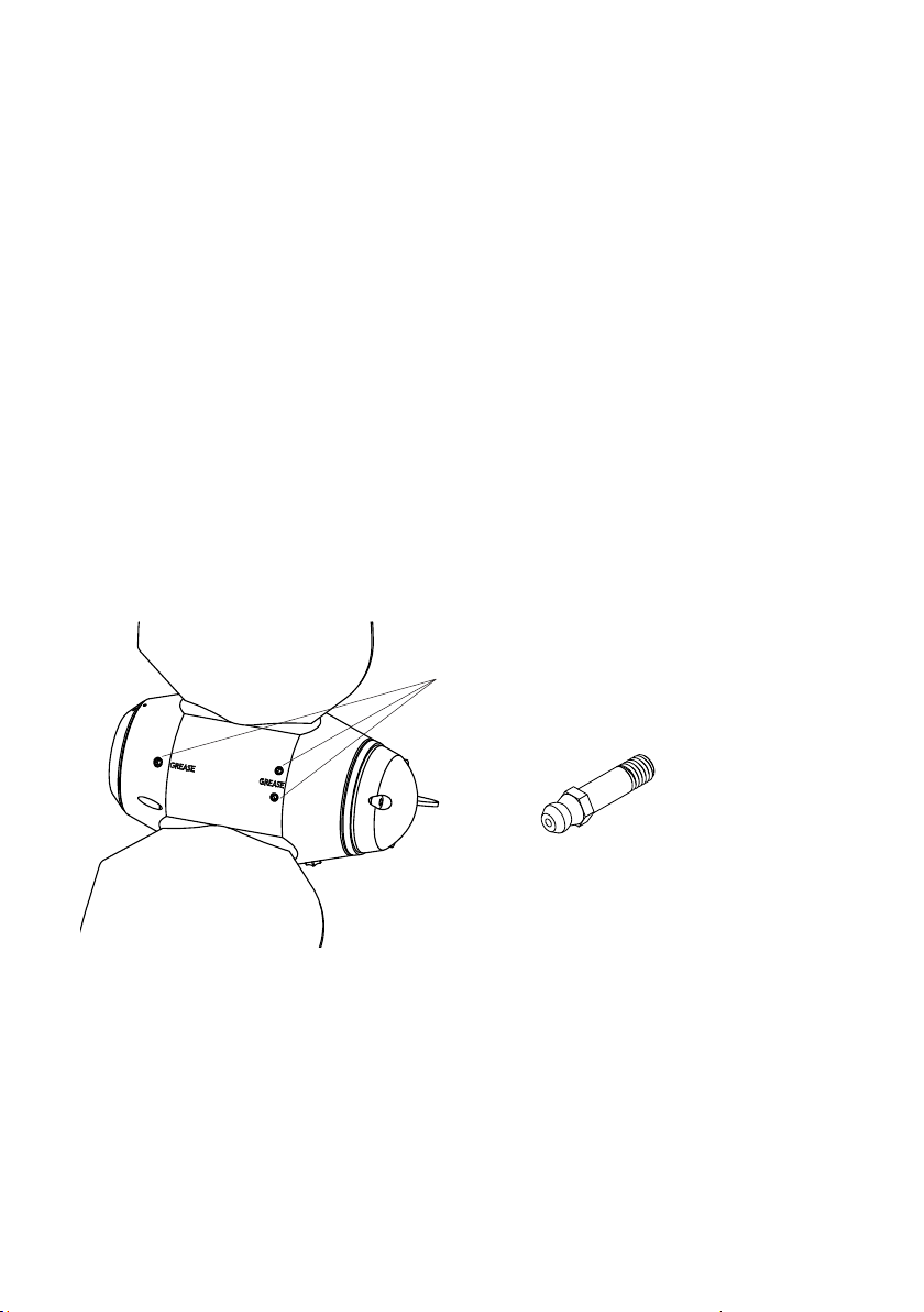
d. Verify that the propeller is full of fluid grease (it must pour) and seep to the
outside of the propeller.
e. Make sure that the propeller is protected from galvanic corrosion by applying
the proper zinc anode on the propeller and drive shaft.
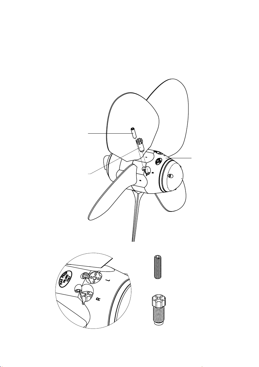
f. Be sure that the values of the forward and backwards motion pitch set on the
propeller you received correspond to those optimal for your boat. If you have
any doubts please refer to the sections 5 and 6 concerning the calculation
and the adjustment of the propeller pitch.
5. HOW TO DETERMINE THE OPTIMAL FORWARD MOTION PITCH
AND / OR THE OPTIMAL BACKWARDS MOTION PITCH
OF THE PROPELLER
The diameter and pitch must be calculated as if MAX PROP®EASY/WHISPER
were a common fixed-pitch propeller. With respect to traditional propellers,
MAX PROP®EASY/WHISPER allows the users to adjust the pitch according to
their needs. This great advantage allows the pitch to be optimized if during
navigation the performance is not completely satisfactory or in case of changed
characteristics of the propulsion system. If the engine does not reach the
operating number of revolutions, then the blade angle αmust be decreased;
if, on the contrary, the operating number of revolutions is exceeded, then the
angle αmust be increased. The fig.4 below shows the theoretical pitches in
millimeters corresponding to the different blade’s angles for a number of
propeller diameters.
With good approximation we can consider that, at the same RPM, the boat
speed varies directly with the variation of angle α. Or that, at the same boat
speed, the RPM of the engine varies inversely with the variation of the angle α.
For example if the angle αis increased by 10%, at the same RPM, the boat speed
will increase by 10% and vice versa . Or, if the angle αis increased by 10%, at the
same boat speed, the RPM of the engine will decrease by 10% and vice versa.
8
p.

Propeller diameter (millimeters)
300
350
400
450
500
550
600
650
700
750
800
αBlades inclination angle (degrees)
10°
100
115
130
150
170
185
200
215
230
250
265
12°
120
140
160
180
200
220
240
260
280
300
320
14°
140
165
190
210
235
260
280
305
330
350
375
16°
160
190
215
245
270
300
325
350
380
405
430
18°
180
215
245
275
305
335
365
400
430
460
490
20°
205
240
275
310
345
375
410
445
480
515
550
22°
230
265
305
340
380
420
455
495
535
570
610
24°
250
295
335
375
420
460
505
554
585
630
670
26°
275
320
370
415
460
505
550
590
645
690
735
28°
300
350
400
450
500
550
600
650
700
750
800
30°
325
380
435
490
545
600
655
705
760
815
870
fig. 4
PRACTICAL EXAMPLE
The user can reach a maximum RPM = 2,730 into forward gear, while
at the same speed he would like his engine to reach an RPM = 3,000.
It is therefore necessary to reduce the angle αpreviously set on the
propeller. If the propeller was set with an angle αof 22 °, the new
angle αshould be 20 °. The proportion is: 2.730 x 22 = 3.000 x 20.
That is, at the same boat speed if you multiply the RPM value detected
in navigation by the value of the corresponding angle α, you get as a
result, a constant.
9
p.

6. DESCRIPTION OF THE PATENTED SYSTEM FOR SETTING
AND / OR VARYING OF THE PITCH
(for convenience all the propeller pitches
will be “improperly” expressed in degrees)
fig. 5
VITE / ASTA DI REGOLAZIONE
DEL PASSO
PITCH ADJUSTMENT
SCREW / ROD
GRANO DI BLOCCAGGIO
LOCKING PITCH
ADJUSTMENT SCREW
VITE/ASTA DI REGOLAZIONE
PITCH ADJUSTMENT
SCREW/ROD
ELICA - PROPELLER
VITE/ASTA DI REGOLAZIONE
DEL PASSO
GRANO DI BLOCCAGGIO
DELLA VITE/ASTA
SCREW/ROD
LOCKING GRUB SCREW
GRANO DI BLOCCAGGIO
DELLA VITE/ASTA
SCREW/ROD
LOCKING GRUB SCREW
10
p.

On the body of each propeller are two threaded holes (housings), marked with
letters “R” and “L”; a screw/rod is inserted in each hole. The pitch of the propeller,
both in forward and backwards position, can be easily varied by changing how
deeply each screw/rod penetrates the propeller body. If the propeller is right-
handed, the forward motion pitch can be changed by acting on the screw/rod
housed in the hole “R” (right) and the backwards motion pitch by acting on the
screw/rod housed in the hole “L” (left). On the contrary, if the propeller is left-
handed the forward motion pitch can be changed by acting on the screw/rod
housed in the hole “L” and the backwards motion pitch by acting on the screw/
rod housed in the hole “R”.
6.1 HOW TO SET THE FORWARD MOTION PITCH
OF THE PROPELLER
a. The forward motion pitch increases by increasing the penetration depth of the
screw/rod supplied in the propeller body or if a longer screw/rod is inserted.
Vice versa decreases by decreasing the penetration depth of the screw/rod
supplied in the propeller body or if a shorter screw/rod is inserted.
b. Each screw/rod used for setting the pitch is provided with a stamped even
number (consisting of 2 digits), corresponding to a precise propeller pitch.
The higher the number stamped on the screw/rod, the longer the screw/rod,
and the greater is the corresponding forward motion pitch.
c. To make the propeller assume the forward motion pitch stamped on the
screw/rod, it is sufficient to completely screw, up to abutment, the screw/rod
into the respective housing. Then lock the screw/rod in said position with a
threaded grub screw. NOTE: If in its abutment/stroke position, the grub screw
does not coincide with any of the grooves dug into the head of the screw/rod, it is
necessary to slightly unscrew the screw/rod until the nearest groove coincides
with the position of the grub screw.
Each MAX PROP®propeller is supplied with two screws/rods already
inserted in the propeller body. A screw/rod sets the forward motion
pitch; the other screw/rod sets the backwards motion pitch. The pitches,
both in forward and backwards position, are the ones requested at order
confirmation.
11
p.

a. The backwards motion pitch increases if the penetration depth of the screw/
rod in the propeller body is reduced or if a shorter screw/rod is inserted in
the respective housing, vice versa decreases by increasing the penetration
depth of the screw/rod in the propeller body or if a longer screw/rod is
inserted in the respective housing.
b. There are three screws/rods available for setting the backwards motion
pitch, stamped respectively with the following numbers: 1, 2, 3. The screw/
rod stamped number 1 is the longest and corresponds to the backwards
motion pitch of 16 degrees. The screw/rod stamped number 2 has an
intermediate length and corresponds to the backwards motion pitch of 20
degrees. The screw/rod stamped number 3 is the shortest and corresponds
to the backwards motion pitch of 24 degrees.
c. To make the propeller assume the backwards motion pitch of 16 degrees,
it is sufficient to completely screw, up to abutment, the screw/rod stamped
number 1. Then lock, with a threaded grub screw, the screw/rod in its
housing. To make the propeller assume the backwards motion pitch of 20
degrees, it is sufficient to completely screw, up to abutment, the screw/rod
stamped number 2. Then lock, with a threaded grub screw, the screw / rod
in its housing. To make the propeller assume the backwards motion pitch of
24 degrees, it is sufficient to completely screw, up to abutment, the screw/
rod stamped number 3. Then lock, with a threaded grub screw, the screw /
rod in its housing.
6.2 HOW TO SET THE BACKWARDS MOTION PITCH
OF THE PROPELLER
PRACTICAL EXAMPLE CONCERNING
THE FORWARD MOTION PITCH
The number 18 is stamped on the screw/rod. As the number 18 consists
of two digits, the screw/rod must be used to set the forward motion
pitch. If the screw/rod 18 is completely screwed up to abutment, the
forward motion pitch of the propeller will be 18 degrees.
12
p.

Max Prop can provide on request additional screws/rods ( a “screws/rods set”)
for varying both the forward motion pitch (screws stamped with the respective
even numbers of two digits) and the backwards motion pitch (screws stamped
with the respective numbers of one digit).
6.3 HOW TO VARY THE FORWARD MOTION PITCH AND
THE BACKWARDS MOTION PITCH OF THE PROPELLER
6.3.1 HOW TO VARY THE PITCH WITH A SET OF SCREWS/RODS
a. Remove the threaded grub screw that locks the pitch adjustment screw/rod
you want to vary.
b. Remove the screw/rod (corresponding to the first pitch) from the propeller
body and screw up to abutment, in the same housing, a second screw/rod
having stamped a different number from the one stamped on the removed
first screw/rod. Then lock the new screw/rod in its housing with the threaded
grub screw. The new propeller pitch will be the one stamped on the second
screw/rod.
6.3.2 HOW TO VARY THE PITCH WITHOUT A SET OF SCREWS/RODS
The patented MAX PROP®propeller pitch adjustment system offers also the
possibility to vary the forward motion pitch and the backwards motion pitch
even without a set of screws/rod. In fact, it is possible to obtain the new pitch
simply by unscrewing, by a precise angle, the screw/rod already inserted in the
propeller body. It is thus possible to obtain all the forward motion pitches lower
than or equal to the number pitch stamped on the screw/rod for adjusting the
forward motion pitch, and all the backwards motion pitches higher than or equal
to the pitch stamped on the screw/rod for adjusting the backwards motion pitch.
a. All of the MAX PROP EASY/WHISPER propellers have been sized so that, by
unscrewing one complete turn (360°) each forward pitch adjustment screw/
rod, the forward motion pitch decreases by four degrees. By unscrewing
one complete turn (360°) each backwards pitch adjustment screw/rod, the
backwards motion pitch increases by four degrees.
13
p.

PRACTICAL EXAMPLE CONCERNING
THE FORWARD MOTION PITCH
In the housing for the forward motion pitch it has been screwed, up to
abutment, a screw/rod stamped 22, therefore the propeller has now
a forward motion pitch of 22 degrees. By unscrewing this screw/rod
by one complete turn, the propeller will take a new forward motion
pitch of 18 degrees (22-4=18). It is therefore possible to set a forward
motion pitch of 18 degrees without having the screw/rod with the
number 18 stamped on it.
PRACTICAL EXAMPLE CONCERNING
THE BACKWARDS MOTION PITCH
In the housing for the backwards motion pitch it has been screwed, up
to abutment, the screw/rod stamped number 1, therefore the propeller
has a backwards motion pitch of 16 °. By unscrewing this screw/rod
by one complete turn, the propeller will take a new backwards motion
pitch of 20 ° (16 + 4 = 20). It is therefore possible to set a backwards
motion pitch of 20 ° without having the screw/rod with the number 2
stamped on it.
b. Eight equidistant grooves are carved in the head of each screw/rod. These
grooves have dual capacity: the first is the one described in the previous
practical examples, that is locking the screw/rod up to abutment by fastening
it with a threaded grub screw. The second function is to precisely define an
intermediate rotation (not in the stop/end position) and lock the screw/rod in
the said intermediate position. It is in fact possible to unscrew each screw/
rod even by a single interval between one groove and the next, or one eighth
of a turn (since the grooves are eight), and lock the screw/rod in said position.
c. As the unscrewing of a complete turn of each forward pitch adjustment screw/
rod decreases the forward motion pitch by four degrees, the unscrewing of
a single interval between one groove and the following one will decrease
the forward motion pitch of half a degree (4 : 8 = 0.5). Unscrewing a single
14
p.

6.4 HOW TO KNOW THE VALUE OF THE PITCH
SET ON YOUR PROPELLER
If the two screws/rods have been both completely screwed up to abutment
in its housings, the forward and the backwards motion pitch of the propeller
correspond to the numbers stamped on the respective screws/rods.
If the screw/rod is not completely screwed up to abutment in its housing,
proceed as follows to know the value of the pitch:
PRACTICAL EXAMPLE CONCERNING
THE FORWARD MOTION PITCH
The screw/rod stamped number 22 has been screwed into its seat up
to abutment, therefore the propeller has a forward motion pitch of
22°. Starting from the stroke position of this screw/rod, if you loosen
three grooves of the screw/rod, the propeller pitch will decrease by
1.5° (0.5 x 3 = 1.5). The propeller will therefore take a new forward
motion pitch of 20.5 ° (22 - 1.5 = 20.5).
PRACTICAL EXAMPLE CONCERNING
THE BACKWARDS MOTION PITCH
A screw/rod stamped number 1 has been screwed in its seat up to
abutment, therefore the propeller has a backwards motion pitch of 16
degrees. By unscrewing the screw/rod of three grooves, the propeller
pitch will increase by 1,5 degrees (0.5 x 3 = 1,5). The propeller will
therefore assume a new backwards motion pitch of 17,5 degrees ( 16
+ 1,5 = 17,5).
interval between one groove and the following one of each backwards pitch
adjustment screw/rod will increase the backwards motion pitch by half a
degree (4 : 8 = 0.5).
15
p.

a. Tighten the screw/rod up to abutment while counting with attention the
number of groove intervals it rotates to come into abutment (and therefore
how many half degrees the propeller pitch has changed). Write down this
variation.
b. Remove the screw/rod and read the number stamped on it.
c. If the screw/rod is the one intended to adjust the forward motion pitch, the
so-founded aforesaid pitch variation must be detracted from the value of
the pitch stamped on such screw/rod , on the contrary, if the screw/rod
is the one intended to adjust the backwards motion pitch, the so-founded
aforesaid pitch variation must be added to the value of the pitch stamped on
such screw/rod.
PRACTICAL EXAMPLE CONCERNING
THE FORWARD MOTION PITCH
To reach the abutment position the forward pitch adjustment screw
/rod has rotated of 5 intervals, that is the forward motion pitch has
increased of 2,5 degrees ( 5 x 05 = 2,5). The number stamped on
the screw/rod is 22 (corresponding to a forward motion pitch of 22
degrees). The propeller forward pitch was therefore set at 19.5
degrees (22 – 2,5 = 19,5).
PRACTICAL EXAMPLE CONCERNING
THE BACKWARDS MOTION PITCH
To reach the abutment position the backwards pitch adjustment screw
/rod has rotated of 5 intervals, that is the backwards motion pitch
has decreased by 2,5 degrees ( 5 x 05 = 2,5). The number stamped
on the screw/rod is 1 (corresponding to a backwards motion pitch of
16 degrees). The propeller backwards pitch was therefore set at 18.5
degrees (16 + 2,5 = 18,5).
16
p.

MAX PROP®EASY / WHISPER propeller gives the possibility to change direction
of propeller rotation, for example if you change the engine or in case of a mere
error when ordering.
(in case you have doubts about the shaft rotation, put the shaft into forward
gear and look the propeller from the stern of the boat to the bow. If the propeller
rotates clockwise, the rotation is right-handed; by contrast, if the propeller rotates
counterclockwise, the rotation is left-handed)
In order to change rotation of your MAX PROP propeller, from right-hand rotation
to left-hand rotation or vice versa, operate as follows referring to fig. 6.
a. Unscrew the locking-zinc screws and remove the zinc
b. Unscrew the locking-nut screws and remove the nut
c. At the aft edge of the hub there is a seeger ring: remove it by using the
special pliers ( supplied on request).
7. HOW TO CHANGE THE DIRECTION
TO THE PROPELLER ROTATION
fig. 6
B ( 1,50 : 1 )
B
VITI BLOCCA-DADO
LOCKING NUT SCREWS
BULINO DI RIFERIMENTO
REFERENCE MARK
ZINCO
ZINC
VITI BLOCCA-ZINCO
LOCKING ZINC SCREWS
ANELLO "SEEGER"
"SEEGER" RING
ANELLO PORTA-ZINCO
ZINC-HOLDING RING
MOZZO
HUB
DADO
NUT
17
p.

d. Remove the zinc–holding ring.
e. Once the zinc-holding ring has been pulled out, you can see that on one tooth
of the hub (aft side) there is a reference mark, and that two teeth of the zinc-
holding ring are marked respectively with “L” (left) and “R” (right).
f. If you place the zinc-holding ring in its seat again, by matching the “R” tooth
with the hub reference mark, you will have a right-hand propeller, on the
contrary by matching the “L” tooth with the hub reference mark you will have
a left-handed propeller (see fig.6).
g. Reinsert the seeger ring in its seat.
h. Tighten the nut and lock it with the locking-nut screws.
i. Place back the zinc and fasten it with the locking-zinc screws.
8. IMPORTANT INSTRUCTIONS FOR
THE PROPELLER USE AND MAINTENANCE
a. The backwards motion must always be engaged starting from the forward
motion position, to avoid the thrust direction of the propeller to be reversed.
Therefore, before putting into the reverse gear, the forward gear has to be
put into for a while.
b. To arrange the blades in the feathered position, the rotation of the propeller
shaft has to be locked while the boat is travelling forward and the propeller
blades are arranged in the forward motion position. To verify if the propeller
blades actually reach the feathered position it is sufficient, while the boat
is still travelling forward, to make the propeller shaft free to rotate by
putting into the neutral gear. If the propeller shaft starts rotting, it means
that the blades are not arranged in the feathered position and, therefore, it
is recommended to fill the propeller body with a very fluid grease (it must
pour).
c. When the boat sails with the engine off, it is suggested to leave the propeller
shaft free to rotate by putting the gear in neutral. However, you should never
sail with the reverse gear engaged.
18
p.

d. Verify that the grease is very fluid so that it pours and seeps to the outside of
the propeller, thereby assuring the lubrification of the surfaces able to rotate
reciprocally. This way, the blades will be arranged in their feathered position
also if the boat travels at low speed.
e. Protect the propeller against galvanic corrosion by applying a sufficient
mass of zinc. Replace the zinc anodes every year even if they have not been
corroded and check that there is good electrical contact between the zinc,
the propeller bronze and the propeller shaft (the contact surfaces between
the zinc and the bronze must be cleaned with abrasive cloth if they have
incrustations).
9. HOW TO SLIP THE PROPELLER OFF
FROM THE PROPELLER SHAFT
fig. 7
VITI A TESTA SVASATA
COUNTERSUNK HEAD SCREWS
ESTRATTORE
PULLER
ANELLO PORTA ZINCO
ZINC-HOLDING RING
VITI A TESTA SVASATA
COUNTERSUNK HEAD SCREWS
ESTRATTORE
PULLER
ANELLO PORTA ZINCO
ZINC HOLDER RING
Referring to fig. 7, operate as follows:
a. Remove the zinc.
b. Remove the two locking-nut screws.
19
p.

c. Verify that the nut is free to loosen and, at the same time, verify which is
the rotation direction for the unscrewing (usually the nut loosens by rotating
anticlockwise).
d. Screw the nut again until it is moved again in abutment against the propeller.
e. Fasten a puller (that is a perforated washer), supplied on request, on the
zinc-holding ring by means of countersunk-head screws.
f. In each threaded hole of the zinc-holding ring, a countersunk-head screw
for locking the extractor (perforated washer) must be inserted. Check that
all the screws work together to hold the extractor against the zinc holder
ring. To do this it is necessary that the longer countersunk-head screws are
screwed into the holes where the nut locking screws were housed; while
the shorter countersunk screws are screwed into the holes where the zinc
locking screws were housed.
g. It is very important to verify that each countersunk-head screw is neither too
long or too short. Each screw must be screwed into its threaded hole for a
length not less than its own diameter. The same screw, when it is completely
screwed (and tightened against the puller) must not touch the bottom of its
threaded hole.
h. Unscrewing the nut carefully, verifying that all the screws collaborate on
bearing the load necessary for extracting the propeller. In other words that
all the countersunk-head screws hold the perforated washer (puller) against
the zinc holder ring.
i. Increase the unscrewing torque to unscrew the nut progressively. We
recommend to not exceed the 200 Newton/meter value ( which corresponds
to a load of 10-20 kg on a one meter length lever) and to apply the unscrewing
stress by interposing pauses.
j. After each pause, and before reapplying the nut unscrewing load, it is
important to check that all the countersunk-head extractor fastening screws
have not loosened. In the event of loosening, it is necessary to tighten again
each screw against the extractor.
k. When the unscrewing of the nut has tensioned all the screws, tap the
propeller body with a plastic mallet. These blows will cause the propeller
hub to come off the propeller shaft.
20
p.
10. IDENTIFICATION FEATURES OF YOUR MAX PROP®
it is useful to fill in and keep the following data
Other manuals for Easy
2
This manual suits for next models
1
Table of contents
Other MAX PROP Marine Equipment manuals
Popular Marine Equipment manuals by other brands

E2S
E2S BExS110D-SIL instruction manual

Raymarine
Raymarine A series Installation and operation instructions

Texecom
Texecom Premier Elite Odyssey-W Series installation manual

bolid
bolid S2000-OPZ instruction manual

Garmin
Garmin Fishfinder 300C Quick start manual

Raymarine
Raymarine DSM30 installation manual