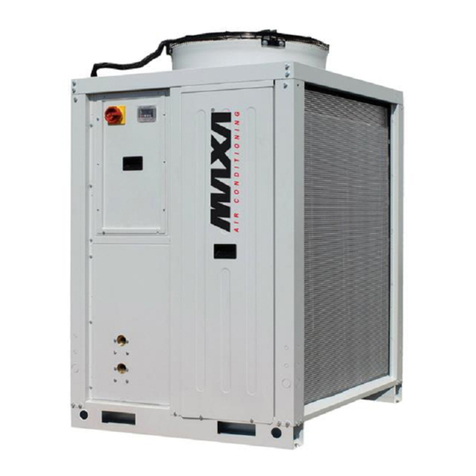
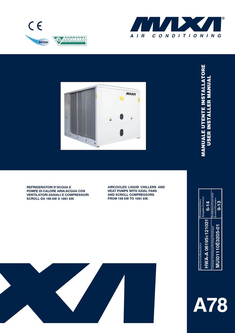
MAXA HWA-ZA User manual

REFRIGERATORID’ACQUAARIA/ACQUAINCLAS-
SEENERGETICA “A”CONVENTILATORIASSIALIE
COMPRESSORI A VITE DA 647 kW A 917 kW
AIRCOOLED LIQUID CHILLERS, ENERGY CLASS
“A”WITHAXIALFANSANDSCREWCOMPRESSORS
FROM 647 kW TO 917 kW
FLÜSSIGKEITSKÜHLER LÜFTGEKÜHLT, ENERGIE
KLASSE “A” MIT AXIALLÜFTERN UND SCHRAUBEN
VERDICHTERN VON 647 kW BIS 917 kW
GROUPES DE PRODUCTION D’EAU GLACÉE,
EN CLASSE ÉNERGÉTIQUE “A” À CONDENSATION
À AIR AVEC VENTILATEURS AXIAUX ET COMPRES-
SEURS À VIS DE 647 kW À 917 kW
AIR CONDITIONING
A42
MANUALE TECNICO
TECHNICAL MANUAL
TECHNISCHES HANDBUCH
MANUEL TECHNIQUE
Serie/Series/Serie/Série Emissione/Edition/
AusgabeIssue
HWA-ZA
02647-V÷02917-V 10.14
Catalogo/Catalogue/Katalog/Brochure Sostituisce/Superseedes
Ersetzt/Remplace
MTE0111092104-02 04.10

2
HWA-ZA

3
HWA-ZA
INDICE Pag.
•Descrizione generale 4
•Versioni 4
•Caratteristiche costruttive 4
•Accessori montati in fabbrica 4-6
•Accessori forniti separatamente 6
•Condizioni di riferimento 6
•Limiti di funzionamento 6
•Caratteristiche tecniche unità in classe "A" 8-9
•Dati tecnici 10-11
•Rese in raffreddamento 12
•Perdite di carico circuito idraulico 13
•Limiti portata acqua evaporatori 13
•Fattori di correzione 13
•Coefficienti correttivi per fattori
di sporcamento evaporatore 13
•Schema circuito frigorifero:
Unità per solo raffreddamento 14
•Circuito idraulico:
Caratteristiche generali 15
Schema circuito idraulico 15
•Unità con serbatoio e pompe:
Dati tecnici 16
Curve caratteristiche delle pompe 17
•Posizione attacchi idraulici 17
•Dimensioni d'ingombro e spazi di rispetto 18
•Distribuzione pesi 19
•Pressione sonora 20
•
Sistema di regolazione con microprocessore
21
•Legenda schemi circuiti elettrici 22
•Schemi circuiti elettrici 23-25
•Consigli pratici di installazione 26
INDEX Pag.
•General description 4
•Versions 4
•Technical features 4
•Factory fitted accessories 4-6
•Loose accessories 6
•Reference conditions 6
•Operating range 6
•
Technical characteristics of units'in energy class "A"
8-9
•Technical data 10-11
•Cooling capacity 12
•Water circuit pressure drops 13
•Evaporator water flow limits 13
•Correction factors 15
•Evaporator fouling factors
corrections 13
•Refrigeration circuit diagram:
Only cooling units 14
•Water circuit:
General characteristics 15
Water circuit diagram 15
•Units with storage tank and pump:
Technical data 16
Characteristic pump curves 17
•Position of water connections 17
•Dimensions and clearances 18
•Weights 19
•Sound pressure level 20
•Microprocessor control system 21
•Wiring diagrams explanation 22
•Wiring diagrams 23-25
•Installation recommendations 26
INHALTSVERZEICHNIS Seite
•Allgemeines 5
•Bauvarianten 5
•Konstruktionsmerkmale 5
•Im Werk montiertes Zubehör 5-7
•Lose mitgelieferten Zubehöre 7
•
Richtwerte Bedingungen am Gerätestandort
7
•Einsatzbereich 7
•Technische Merkmale der Anlagen der
Energieklasse "A" 8-9
•Technische daten 11
•Kälteleistungen 12
•Wärmetauscher-Druckverlust e des
hydraulischen Kreislaufs 13
•Verdampfer Wassermengerenzen 13
•Korrektionfaktoren 13
•Korrekturkoeffizienten für
Verschmutzungsfaktoren 13
•Kältekreislaufschema:
Einheit nür Kühlung 14
•Wasserkreislauf:
Allgemeine Merkmale 15
Hydraulisches Schema 15
•Einheit mit Behälter und Pumpen:
Technische daten 16
Pumpenkennlinien 17
•Anordnung der Wasseranschlüsse 17
•Außenmaße und Raumbedarf 18
•Gewichtsverteilung 19
•Schalldruckpegel 20
•
Funktion und ausstattung der Mikroprozessorregelungen
21
•Schaltpläne Erklärung 22
•Schaltpläne 23-25
•Hinweise zur Installation 26
INDEX Pag.
•Généralités 5
•Versions 5
•Caractéristiques techniques 5
•Accessoires montés en usine 5-7
•Accessoires fournis separement 7
•Conditions de référence 7
•Limites de fonctionnement 7
•Caracteristiques techniques des unites de classe
energetique "A" 8-9
•Données techniques 11
•Puissance frigorifique 12
•Pertes de charge circuit hydraulique 13
•Limites débit d'eau evaporateur 13
•Facteurs de correction 13
•Coefficients correcteurs pour facteurs
d’encrassements évaporateur 13
•Schema du circuit frigorifique:
Groupe de production d’eau glacée 14
•Circuit hydraulique:
Caractéristiques générales 15
Circuit hydraulique 15
•Unité avec ballon et pompes:
Données techniques 16
Courbes caractéristiques 17
•Position des raccords hydrauliques 17
•Encombrements et espaces pour entretien 18
•Distribution des poids 19
•Niveaux de pression sonore 20
•Systeme de réglage avec microprocesseur 21
•Explication de le diagrammes 22
•Diagrammes électriques 23-25
•Conseils pratiques pour l'installation 26

4
HWA-ZA
DESCRIZIONE GENERALE
Refrigeratori d’acqua ad alta efficienza, in classe energetica “A”,
condensati ad aria con ventilatori assiali per installazione esterna.
La gamma comprende 3 modelli che coprono potenzialità frigorife-
re da 647 a 917kW.
VERSIONI:
HWA-ZA - solo raffreddamento
HWA-ZA/SSL - solo raffreddamento super silenziata
CARATTERISTICHE COSTRUTTIVE:
Struttura. Di tipo autoportante, realizzata in lamiera zincata con
un’ulteriore protezione ottenuta tramite verniciatura a polveri po-
liestere. I pannelli, facilmente rimovibili, permettono l’accesso al-
l’interno dell’unità per le operazioni di manutenzione e riparazione.
Compressori. Semiermetici a vite, con separatore olio, filtro sul-
l’aspirazione, riscaldatore del carter, spia livello olio, protezione
termica, rubinetto di mandata e sistema di regolazione della capa-
cita’ in continuo.
Ventilatori. Di tipo assiale direttamente accoppiati a motori trifase
a rotore esterno. Una rete di protezione antinfortunistica è posta
sull’uscita dell’aria. Per le unità super silenziate si utilizzano venti-
latori a basso numero di giri e di conseguenza, per alcuni modelli,
aumenta il numero dei ventilatori.
Condensatore. Costituito da due batterie alettate con tubi in rame
ed alette in alluminio.
Evaporatore. Del tipo a mantello e fascio tubiero con due circuiti
indipendenti sul lato refrigerante ed uno sul lato acqua.
Quadro elettrico. Include: interrutto
re generale con bloccoporta, fu-
sibili, relè termici a protezione dei compressori e termocontatti per i
ventilatori, relè di interfaccia e morsetti per collegamenti esterni.
Microprocessore per la gestione automatica dell’unità. Permette di
visualizzare in qualsiasi istante lo stato di funzionamento dell’unità,
di controllare la temperatura dell’acqua impostata e quella effettiva
e, in caso di blocco parziale o totale dell’unità, di evidenziare quali
sicurezze sono intervenute.
Dispositivo elettronico proporzionale per l’attenuazione del li-
vello sonoro, ottenuta mediante regolazione in continuo della ve-
locità di rotazione dei ventilatori; tale dispositivo permette anche il
funzionamento dell’unità fino a temperature dell’aria esterna di 0°C.
Circuito frigorifero versioni HWA-ZA e HWA-ZA/SSL.
Ciascuna unità include due circuiti frigoriferi indipendenti. Realizzato in
tubo di rame, comprende per tutti i modelli i seguenti componenti: val-
vola di espansione termostatica elettronica, economizzatore, rubinetto
sulla linea del liquido, filtro disidratatore, indicatore di liquido ed umidità,
pressostati di alta e bassa pressione (a taratura fissa), valvola di sicu-
rezza e manometri di alta e bassa pressione.
Circuito idraulico versioni HWA-ZA, HWA-ZA/SSL.
Include: evaporatore, sonda di lavoro, sonda antigelo e scarico ac-
qua.
ACCESSORI MONTATI IN FABBRICA:
IM - Interrutorimagnetotermiciinalternativa afusibilie relètermici.
SL - Silenziamento unità. I compressori vengono dotati di co-
pertura fonoisolante.
CC - Controllo condensazione ottenuto tramite la regolazione in
continuo della velocità di rotazione dei ventilatori fino a temperature
dell’aria esterna di –20°C.
BT - Bassa temperatura, necessario nei casi di funzionamento
dell'unità in condizioni di uscita dell'acqua all'evaporatore inferiore
ai 5°C. dei ventilatori fino a temperature dell’aria esterna di –20°C.
HR - Desurriscaldatore con recupero del 20%.
HRT/S - Recuperatore calore totale in serie con recupero dal
70% al 95%, a seconda delle condizioni di lavoro.
HRT/P - Recuperatore calore totale in parallelo con recupero
del 100%.
SP - Serbatoio inerziale 1100 l: modelli 02647 ÷ 02917.
PU - Pompa di circolazione inserita all’interno dell’unità.
PD - Doppia pompa di circolazione inserite all'interno dell'unità;
le pompe lavorano una in stand-by all'altra e ad ogni richiesta di
accensione viene attivata per prima la pompa con meno ore di
funzionamento.
SPU - Serbatoio inerziale e pompa di circolazione inseriti
all’interno dell’unità.
SPD - Serbatoio inerziale e doppia pompa di circolazione
inseriti all’interno dell’unità; le pompe lavorano una in stand-by
all'altra e ad ogni richiesta di accensione viene attivata per prima
la pompa con meno ore di funzionamento.
RF - Rubinetto circuito frigorifero sulla linea del liquido.
GENERAL DESCRIPTION
High efficiency water chillers, energy class “A”, aircooled with
axial fans for outdoor installation. The range consists of 10 mod-
els covering a cooling capacity from 647 to 917kW.
VERSIONS:
HWA-ZA - cooling only
HWA-ZA/SSL - super silenced cooling only
TECHNICAL FEATURES:
Frame. Self-supporting galvanized steel frame further protected
with polyester powder painting. Easy to remove panels allow ac-
cess to the inside of the unit for maintenance and other necessary
operations.
Compressors. Screw semihermetic, with built-in oil separator,
suction filter, cranckcase heater, oil sight glass, thermal protection,
hot gas shut off valves and stepless capacity steps.
Fans. Axial fans directlycoupled to a three-phase electricmotor with
external rotor. A safety fan guard is fitted on the air flow discharge.
On the super silenced units there are fans with a low rpm therefore
some models have more fans.
Condenser. Two copper tube and aluminium finned coils.
Evaporator. Shell and tube, with two indipendent refrigerant circuits
and one water circuit.
Electrical board. Includes: main switch with door safety interlock;
fuses,overloadprotectionforcompressorsandthermocontactsforfans;
interface relays and electrical terminals for external connections.
Microprocessor for automatic control of the unit allowing continu-
ous display of the operational status of the unit, control set and real
water temperature and, in case of partial or total block of the unit,
indication of security device that intervened.
Electronic proportional device to decrease the sound level,
with a continuous regulation of the fan speed. This device allows
also the cooling functioning of the unit by external temperature
till 0°C.
Refrigerant circuit versions HWA-ZA and HWA-ZA/SSL.
Each unit includes two independent refrigerant circuits. Produced in
copper tubing, all models have the following components: electronic
expansion valve, economizer, shut off valve on liquid, filter-drier,
level and humidity indicator, high and low pressure switches (with
fixed setting), safety valve and BP/HP manometers.
Water circuit HWA-ZA, HWA-ZA/SSL version.
Includes: evaporator, temperature sensor, antifreeze sensor and
water drain.
FACTORY FITTED ACCESSORIES:
IM - Magnetothermic switches instead of fuses and thermal
relays.
SL - Unit silencement. The compressors are equipped with
soundbsorbing covering.
CC - Condensation control obtained by means of continuous
adjustment of the fan rotation speed up to outside air temperatures
of –20°C.
BT - Low temperature kit, required in case the unit will work with
evaporator’s outlet water temperature below 5°C.
HR - Desuperheater with 20% heat recovery.
HRT/S - Total heat recovery serial connected for from 70% to
95% heat recovery, according to the working conditions.
HRT/P - Desuperheater with 100% heat recovery.
SP - Inertial tank 1100 l: models 02647 ÷ 02917.
PU - Circulating pump inserted inside the unit.
PD - Double circulating pump installed in the unit, working
one in stand-by to the other; by every start request, the
pump with the least number of working hours is activated
first.
SPU - Inertial tank and circulating pump installed in the unit.
SPD - Inertialtankanddoublecirculating pumpinstalled in the
unit, working one in stand-by to the other; by every start request,
the pump with the least number of working hours is activated first.
RF - Cooling circuit shut off valves on liquide line.

5
HWA-ZA
ALLGEMEINE EIGENSCHAFTEN
Hoch Effizienz kaltwassersätze, Energie Klasse „A“, Lüftgekühlt
mit Axialventilatoren für Aussenaufstellung. Die Produktpalette
besteht aus 3 Modellen, die Kälteleistungsbereich von 647 bis
917kW abdecken.
BAUVARIANTEN:
HWA-ZA - nur Kühlung
HWA-ZA/SSL - nur Kühlung, super schallisoliert
KONSTRUKTIONSMERKMALE:
Struktur. Selbsttragend, aus verzynktem Blech und Polyesterlack
pulverbeschichtet. Die Bleche sind zur Wartung- und Reparaturar-
beiten einfach abnehmbar.
Verdichter. Halbhermetisch schrauben mit intergriertem Ölabschei-
der, Ansaugfilter, Carter Ölwannenheizung, Ölschauglas, thermi-
schen Schutz, Absperrventile auf der Druckseite und stufenlose
Leistungsregelung.
Lüfter. Axialgebläse direkt an dreiphasischen Motor mit externem
Rotor angeschlossen. Auf der Luftdruckseite ist einen Schutzgitter
eingebaut. Für die super schallgedämmten Einheiten werden Lüfter
mit niedrigem Drehzahl verwendet und infolgedessen auf einigen
Modellen werden mehrere Lüfter installiert.
Verflüssigerregister. Bestehend aus zwei Wärmetauscher mit
Aluminium gerippten Lamellen und Kupferrohren.
Verdampfer. Rohrbündel Mantel mit zwei unabhängigen Kältekreis-
läufen und einem auf der Wasserseite.
Schaltschrank.Enthält:HauptschalteralsTürverriegelung,Sicherungen,
thermische Relais als Verdichter Schutz und thermische Kontakte für die
Lüfter, Interface Relais und Klemmen für externen Anschlüsse.
Mikroprozessor. Für die automatische Regelung der Einheit. Zu
jeder Zeit ermöglicht die Anzeige des Betriebszustandes, die An-
zeige der eingestellten und effektiven Wassertemperatur und, im
Fall von teilweisen oder ganzen Einheit Störung, die Feststellung
der eingeschalteten Sicherungen.
Elektronische proportionale Vorrichtung zur Schalldämpfung
mit einer modulanten Lüfter Drehzahlregelung. Diese Vorrichtung
ermöglicht den Kühlbetrieb der Einheit auch bei externer Tempe-
ratur bis 0°C.
Kältekreislauf Versionen HWA-ZA e HWA-ZA/SSL.
Jede Einheit enthält zwei unabhängige Kreisläufe aus
Kupfer Rohrleitungen bestehend aus: elektronische ther-
mostatischem Expansionsventil, Economizer, Absperrventile
auf der Flüssigkeitsseite, Trockenfilter, Flüssigkeit- und
Feuchtigkeitsschauglas, Hoch- und Niederdruckschalter (fix
eingestellt), Sicherheitsventil und Hoch- und Niederdruck-
manometer.
Wasserkreislauf HWA-ZA, HWA-ZA/SSL Versionen.
Enthält: Verdampfer, Betriebsfühler, Frostschutzfühler und Wasser
Entladen.
IM WERK MONTIERTES ZUBEHÖR:
IM - Motorschutzschalterersetzen Sicherungen und thermische
Relais.
SL - Schalldämmung Einheit. Die Kompressoren werden mit
einer schalldämmenden Abdeckung ausgestattet.
CC - Kondensationskontrolle durch kontinuierliche Regulierung
der Laufgeschwindigkeit der Gebläse bis zu einer Temperatur der
Außenluft von -20°C.
BT– Niedrige Temperatur, nötigfallsdieWasseraustrittTemperatur
niedriger als 5°C ist.
HR - Überhitzungsschutz mit 20% Wärmerückgewinnung.
HRT/S - Total Wärmerückgewinner seriell angeschlossen zur von
70% bis 95% Wärmerückgewinnung, gemäß den Arbeitsbedingungen.
HRT/P - Wärmerückgewinner mit einer Rückgewinn. von 100%
der Wärme.
SP - Isolierbehälter 1100 l: Modelle 02647 ÷ 02917.
PU - In die Einheit eingebaute Umwälzpumpe.
PD - Doppelte Umwälzpumpe. In die Einheit eingebaut. Funk-
tionieren in abwechselndem Stand-by. Bei jedem Einschaltim-
puls wird zuerst die Pumpe mit den wenigsten Betriebsstunden
eingeschaltet.
SPU - Pufferspeicher und Doppelumwälzpumpe in den
Einheiten eingebaut.
SPD - Pufferspeicher und Doppelumwälzpumpe in den
Einheiten eingebaut; die Pumpen laufen in stand by und bei
jeder Einschaltung wird die Pumpe freigegeben, die wenigste
Betriebsstunden hat.
RF - Absperrventile auf dem Kaltekreislauf.
DESCRIPTION GÉNÉRALE
Réfrigérateurs d’eau à haute efficacité, en classe énergétique
«A», condensés à air avec ventilateurs axiaux pour installation
à l’extérieur. La gamme est composée de 3 modèles d’une puis-
sance de 647 jusqu’à 917kW.
DIFFÉRENTES VERSIONS:
HWA-ZA - uniquement refroidissement
HWA-ZA/SSL - uniquement refroidissement ultra silencieux
CARACTERISTIQUES:
Structure. Structure autoportante en tôle galvanisée et protégée
par une couche de peinture à poudre polyestère. Les panneaux
sont faciles à enlever permettant un accès total à l'intérieur de
l'unité pour toutes les opérations de maintenance et réparation.
Compresseur. À vis semihermetique, avec separateur de l’hui-
le incorporé, filtre sur l’aspiration, réchauffage de l’huile, voyant
pour niveau del l’huile, protection thermique, robinets sur refoule-
ment et régulation continue de la puissance.
Ventilateurs: de type axial, directement accouplés à des
moteurs triphasés à rotor externe. Une grille de protection antic-
cident est située sur la sortie d’air. Pour les unités supersilen-
ciées on utilise des ventilateurs à basse vitesse de rotation et
donc, pour certaines modèles, on augmente le nombre des ven-
tilateurs.
Condenseur. Deux batteries en tuyaux de cuivre et ailettes en
aluminium.
Evaporateur. Échangeur à faisceaux de tuyaux avec deux cir-
cuits indipéndants sur coté gaz et un sur coté eau.
Tableau electrique. Comprend: sectionneur générale sur porte, fusibles,
relais de protection thermique pour compresseur et contacteurs thermiques
pour ventilateurs, relais d'interface et bornier pour raccordements extérieurs.
Microprocesseur pour gérer automatiquement l'unité ce qui per-
met de visualiser sur voyant les paramètres de fonctionnement
de la machine, de contrôler le point de consigne et température
réelle de l'eau, et, en cas d'arrêt partiel ou total de l'unité, d'indi-
quer l'alarme correspondante.
Dispositif électronique proportionnel pour l’atténuation du niveau
sonore, obtenue au moyen de régulation en continu de la vitesse de
rotation des ventilateurs. Cet dispositif permet aussi le fonctionnement de
l’unité en refroidissement jusq’à des températures de l’air extérieur de 0°C.
Circuit frigorifique versions HWA-ZA et HWA-ZA/SSL.
Chaque unité comprend deux circuits frigorifiques indépendants.
Réalisé en tuyau de cuivre, pour tous les modèles sont inclus les
composants suivants: vanne d’expansion thermostatique électro-
nique, économiseur, robinets sur liquide, filtre déshydrateur, voyant
de liquide et d’humidité, pressotats de haute et basse pression (à
calibrage fixe), soupape de securité et manomètres HP/BP.
Circuit hydraulique versions HWA-ZA, HWA-ZA/SSL.
Le circuit inclut: évaporateur, sonde de travail, sonde anti-gel et
vidange d'eau.
ACCESSOIRES MONTÈS EN USINE:
IM - Interrupteurs magnétothermiques en alternative des
fusibles et relais thermique.
SL - Unité munie de silencieux. Les compresseurs sont munis
d’une couverture isolante acoustique.
CC - Contrôle condensation obtenu au moyen du réglage en
continu de la vitesse de rotation des ventilateurs jusqu’à des
températures extérieures de l’air de - 20°C.
BT-Nécessaireencas defonctionnementdel'unité enconditions
de la sortie eau de l'évaporateur inférieure a 5°C.
HR - Désurchauffeur avec récupération de 20%.
HRT/S - Récupérateurchaleurtotaleensérieavecrécupération
du 70% au 95%, selon les conditions de travail.
HRT/P - Récupérateur chaleur totale avec récupération de
100%.
SP - Ballon tampon 1100 l: modèles 02647 ÷ 02917.
PU - Pompe de circulation insérée à l’intérieur de l’unité.
PD - Double pompe de circulation. Insérées à l’intérieur de
l’unité, une travaille en stand-by à l’autre et à chaque demande
d’allumage, la pompe avec moins d’heures de fonctionnement
sera activée en premier lieu.
SPU - Ballon tampon et pompe de circulation insérées à
l’intérieur de l’unité.
SPD - Ballon tampon et double pompe de circulation insé-
rées à l’intérieur de l’unité; une travaille en stand-by à l’autre et à
chaque demande d’allumage, la pompe avec moins d’heures de
fonctionnement sera activée en premier lieu.
RF - Robinets circuit frigo sur la ligne liquide.
6
HWA-ZA
CONDIZIONI DI RIFERIMENTO
I dati tecnici, indicati a pagina 10 e 11 si riferiscono alle seguenti
condizioni di funzionamento:
- in raffreddamento:
• temperatura ingresso acqua fredda 12°C
• temperatura uscita acqua fredda 7°C
• temperatura ingresso aria condensatore 35°C.
Il livello di pressione sonora é rilevato in campo libero a 1m di distan-
za e ad 1,5 m d'altezza lato batteria condensante con la macchina
funzionante a pieno carico; non tiene conto di eventuali pompe
installate all'interno dell'unità. Questo valore può variare secondo
il luogo d'installazione ed ha una tolleranza di +/- 3dB(A) secondo
DIN 45635. L'alimentazione elettrica di potenza é 400V/3Ph/50Hz;
l'alimentazione elettrica ausiliaria é 230V/1Ph/50Hz.
*
Può essere portata a -20°C con accessorio controllo di condensazione.
** Salvo dove diversamente limitato nelle tavole a pag. 14.
(1) In ogni caso la portata d'acqua dovrà rientrare nei limiti riportati a pag. 15
REFERENCE CONDITIONS
All technical data, indicated on pages 10 e 11, refer to the following
unit operating conditions:
- cooling:
• entering water temperature 12°C
• leaving water temperature 7°C
• ambient air on condenser 35°C.
The sound pressure level is measured in free field conditions at a
distance of 1 m from the unit and at a height of 1,5 m side of con-
densing coil and with machine running on full load; it does not take
into account possible pumps installed inside the unit. This value
can vary depending on the site of installation and has a tolerance
of +/- 3dB(A) in accordance with DIN 45635. The power supply is
400V/3Ph/50Hz; auxiliary supply is 230V/1Ph/50Hz.
* This value can be reduced until -20°C with an optional accessory
supplied prefabricated.
** Exept where it is differently limitated in the tables pag. 14.
(1) In all cases the water range will have to re-enter within the reported
limits on pag. 15.
FE - Resistenzaantigeloevaporatoreadinserimentotermostatato.
FU - Resist. antigelo evaporatore per SPU ad inserimento
termostatato.
FD - Resist. antigelo evaporatore per SPD ad inserimento
termostatato.
SS - Soft start per la limitazione della corrente di spunto all'av-
viamento del compressore.
Web Monitoring: permette il monitoraggio e la gestione remota
dell'unità tramite protocollo di communicazione GPRS/GSM/
TCP-IP. Gli utenti abilitati all'utilizzo di questo servizio possono,
tramite opportuna pagina Web, accedere alle attività di monitoring,
Gestione e Statistica.
CP - Contatti puliti per segnalazione a distanza.
ACCESSORI FORNITI SEPARATAMENTE:
MN-Manometrialta/bassa pressione per ogni circuito frigorifero .
CR - Pannello comandi remoto da inserire in ambiente per il
comando a distanza dell’unità, con funzioni identiche a quello
inserito in macchina.
IS - Interfaccia seriale RS 485 per collegamento a sistemi di
controllo e di supervisione centralizzati.
RP - Reti protezione batterie in acciaio con trattamento di cata-
foresi e verniciatura.
FP - Reti protezione batterieconfiltro metallico di tipo a matassa.
AG - Antivibranti in gomma da inserire alla base dell’unità per
smorzare eventuali vibrazioni dovute al tipo di pavimento ove la
macchina è installata.
AM- Antivibranti a molla da inserire alla base dell’unità per
smorzare eventuali vibrazioni dovute al tipo di pavimento ove la
macchina è installata.
FL - Flussostato a protezione dell'evaporatore da possibili inter-
ruzioni del flusso d'acqua.
FE - Evaporator heater with thermostatic control.
FU - Evaporator heater for SPU with thermostatic control.
FD - Evaporator heater for SPD with thermostatic control.
SS - Soft start to reduce compressor starting current.
WM - Web Monitoring: monitoring enables remote management
of the system through communication protocols, GPRS/GSM/
TCP-IP. Authorized users have access to a dashboard display
that provides critical system information from which the user
can measure, manage and report as necessary.
CP - Potential free contacts for remote alarm and control.
LOOSE ACCESSORIES:
MN-Highandlowpressure gauges for every refrigeration circuit.
CR - Remote control panel to be inserted in the room for remote
control of the unit, with the same functions as that inserted in the
machine.
IS - RS 485 serial interface for connection to controls and cen-
tralized supervision systems.
RP - Coil protection guards in steel with cataphoresis treatment
and painting.
FP - Coil protection grills with nest metal filter.
AG - Rubber vibration dampers to be inserted at the bottom
of the unit to dampen possible vibrations due to the type of floor
where the machine is installed.
AM- Spring shock absorbers to be inserted at the bottom of the
unit to dampen possible vibrations due to the type of floor where
the machine is installed.
FL - Flow switch to prevent any water flow interruption.
LIMITI DI FUNZIONAMENTO Raffreddamento
Cooling OPERATING RANGE
min max
Temperatura acqua in ingresso °C 820
Inlet water temperature
Temperatura acqua in uscita °C 515
Outlet water temperature
Salto termico acqua (1) °C 39
Water thermal difference (1)
Temperatura aria esterna °C 0* 52** Ambient air temperature
Minima temperatura dell’acqua
refrigerata con l’impiego di glicole °C -8 Minimun chilled water outlet
temperature with glycol mixture
Max. pressione di esercizio lato
acqua scambiatore kPa 1000 Max. operating pressure heat
exchanger water side

7
HWA-ZA
CONDITIONS DE RÉFÉRENCE
Les données techniques, indiquées page 12 et 13; se réfèrent aux
conditions de fonctionnement suivantes:
- refroidissement:
• température d’entrée de l’eau froide: 12°C;
• température de sortie de l’eau froide: 7°C;
• température d’entrée de l’air condenseur: 35°C.
Le niveau de pression sonore est relevé en champ libre à 1m
de distance et à 1,5m de hauteur côté batterie de condensation
avec la machine à pleine charge. Cette valeur peut varier en
fonction du lieu d’installation et a une tolérance de +/- 3dB(A)
selon DIN 45635. L’alimentation électrique de puissance est
de 400V/3Ph/50Hz, l’alimentation électrique auxiliaire est de
230V/1Ph/50 Hz.
* Il peut être jusq'à -20 C avec l'accessoire controle de condensation.
**
Sauf dans les zones diffèremment limitées dans les tableaux pag. 14.
(1) Dans chacun des cas la portée d'eau devra rentrer dans
limites reportées à page 15.
BEZUGS - UND AUSLEGUNGSDATEN
DiehierangegebenentechnischenDaten, Seite12und13, beziehen
sich auf folgenden Auslegungsdaten:
- im Kühlbereich:
• Kaltwassereintrittstemperatur: 12°C;
• Kaltwasseraustrittstemperatur: 7°C;
• Lufteintrittstemperatur am Verflüssigerregister 35°C.
Der Schalldruckpegel wurde im Freien in einem Abstand von 1m vor
dem Luftansaug seite und in einer Höhe von 1,5m unter Vollast der
Anlage ermittelt;eventuell in die Einheit eingebaute Pumpen sind
nicht berücksichtigt. Der Wert kann an anderen Aufstellungsorten
varieren. Meßtoleranz +/- 3dB(A) nach DIN 45635. Separate Ein-
speisung von 400V/3Ph/50Hz; Steuerspannung 230V/1Ph/50Hz
wird mittels montierte Trenntrafos erzeugt.
* Es kann auf -20°C mit dem Zusatzgerät reduziert werden
Kondensation Kontrolle.
**
Auß er wo dieses in den Tafeln auf Seite Nr. 14 anders erklärt wird.
(1) Die Wasser Durchflußmenge muss jedenfalls den auf der Tabelle
Seite 15 Grenzen entsprechen.
FE - Begleitheizung am Verdampfer Thermostat geregelt.
FU - Begleitheizung am Verdampfer für SPU Thermostat gere-
gelt.
FD - Begleitheizung am Verdampfer für SPD Thermostat gere-
gelt.
SS - SanftanlasserzurReduzierungdesVerdichterAnlaufstroms.
WM - Web-Überwachung: ermöglicht die Über wachung und ein
Remote-Managment des Gerätes über das Kommunikationspro-
tokollGPRS/GSM/TCP-IP. Aktiviert der Nutzer diesenDienst, kann
durch den Zugriff auf eine entsprechende Web-Seite, der Status
der Gerätes abgefragt werden, sowie verschiedene Statistik- und
Managment-Informationen abgerufen werden.
CP - Potentialfreie Kontakte für externe Ein/Ausschaltung.
LOSE MITGELIEFERTEN ZUBEHÖRE:
CR - Fernbedienung die am Standort installiert wird und von der
aus eine Fernsteuerung der Einheit möglich ist. Mit den gleichen
Funktionen wie das Gerät.
IS - Serielle Schnittstelle RS 485 für den Anschluss an Kontrol-
llsysteme oder zentrale Supervisor.
RP - Schutzgitter Verflüssigerregister aus Stahl mit Katapho-
resebehandlung und Lackierung.
FP - Schutzgitter für Verflüssigerregister mit Metallfilter als
Metallnetz. AG - Gummi Schwingungsdämpfer werden unter
der Einheit zur Dämpfung eventueller Vibrationen eingesetzt, die
von dem Bodentyp verursacht werden können, auf dem die Einheit
installiert ist.
AM- Feder Schwingungsdämpfer werden unter der Einheit zur
Dämpfung eventueller Vibrationen eingesetzt, die von dem Boden-
typ verursacht werden können, auf dem die Einheit installiert ist.
FL - Strömungswächter zur Wassermängel Vermeidung am
Verdampfer.
FE - Resistances antigel evaporateur contrôle thermostatique.
FU - Resistances antigel evaporateur pour SPU contrôle ther-
mostatique.
FD - Resistances antigel evaporateur pour SPD contrôle ther-
mostatique.
SS - Soft start pour reduction courant au demarrage du compres-
seur.
WM - permet le monitoring et la gestion à distance de l'unité à
travers le protocole de communication GPRS/GSM/TCP-IP. Les
utilisateursautorisés à l’utilisation de ceservice peuvent, en accéd-
ant à la page Web adéquate, visualiser l’état de fonctionnement de
l’unité et opérer diverses actions sur celle-ci telles que Monitoring,
Gestion et Statistiques.
CP - Contcts secs pour signalisation à distance.
ACCESSOIRES FOURNIS SEPAREMENT:
CR - Tableau de commandes à distance à insérer dans un envi-
ronnement pour la commande à distance de l’unité, avec fonctions
identiques à celles insérées dans la machine.
IS - Interface de série RS 485 pour branchement à système de
contrôle et de supervision centralisées.
RP - Réseaux de protection batterie en acier avec traitement
cataphorèse et vernissage.
FP - Grilles de protection batterie avec filtre metallique entre-
croisé.
AG - Antivibreurs en caoutchouc à insérer à la base de l’unité
pour estomper les vibrations éventuelles dues au type de sol sur
lequel la machine est installée.
AM- Antivibreurs à ressort à insérer à la base de l’unité pour
estomper les vibrations éventuelles dues au type de sol sur lequel
la machine est installée.
EINSATZBEREICH
Kühlung
Refroidissement LIMITES DE
FONCTIONNEMENT
min max
Wassereintrittstemperatur °C 820
Température eau entrée
Wasseraustrittstemperatur °C 515
Température eau sortie
Wassertemperaturdifferenz (1) °C 39
Ecart de température (1)
Umgebungstemperatur °C 0* 52** Température air extérieur
Min. Temperatur des gekühlten
Wasser mit Verwendung von
Glykol °C -8 Température minimun de l’eau
glacée avec glycol
Max. Betriebsdruck
Wärmetauscher- Wasser-Seite kPa 1000 Pression maximun d’utilisation
échangeur côte eau

8
HWA-ZA
CARATTERISTICHE TECNICHE UNITA’ IN
CLASSE ENERGETICA “A”
RISPARMIO ENERGETICO:
Le unità in classe energetica “A” presentano valori di E.E.R.
maggiori di 3,1 grazie ad un ridotto assorbimento elettrico e
un’elevata efficienza del binomio compressori-scambiatori.
AFFIDABILITA’:
Scambiatoridicaloregenerosamentedimensionatie compressori
adelevataefficienza consentono dimantenerepressioni di lavoro
relativamente basse (grazie anche all’uso del fluido refrigerante
R134a); tutto ciò permette ai compressori che equipaggiano le
unità in classe “A” di essere meno sollecitati e quindi di essere
soggetti a minori guasti e a minori costi di manutenzione
rispetto a quelli installati nelle unita' tradizionali. Inoltre, per le
loro caratteristiche di elevata efficienza, hanno la possibilità di
funzionare al 100% della loro potenza con temperature dell’aria
esterna fino a 52°C.
COMFORT:
Regolazione in continuo della capacità dei compressori e valvole
di espansione termostatiche su tutta la serie, che permettono la
parzializzazione della potenza frigorifera fino al 12% del carico
termico totale, garantiscono la costanza della temperatura
dell’acquaall’impiantoinqualsiasicondizione.Inoltre, la soluzione
di inserire i compressori in un vano tecnico acusticamente
isolatoe di allestire unità supersilenziate ottenute aumentandole
dimensioni degli scambiatori rende queste unità particolarmente
adatte in installazioni dove ridotti consumi energetici ed elevata
silenziosità sono indispensabili per un ottimale esecuzione
dell’impianto.
TECHNISCHE MERKMALE DER ANLAGEN DER
ENERGIEKLASSE „A“
SPARSAME ENERGIEVERWENDUNG:
Die EER-Werte der zu Energieklasse „A“ gehörenden Anlagen
liegen über 3,1. Grund dafür ist nicht nur ihr geringer Strom-
verbrauch, sondern auch ihre leistungsstarke Kompressoren-
Wärmeaustauscher-Gruppe
ZUVERLÄSSIGKEIT:
Dank der großzügig dimensionierten Wärmeaustauscher und
der leistungsstarken Kompressoren (sowie dank der Verwen-
dung des Kühlmittels R134a) ist es möglich, die Betriebsdrü-
cke ziemlich niedrig zu halten; das Ganze führt dazu, dass die
Kompressoren der Energieklasse-„A“nlagen weniger bean-
sprucht werden, demzufolge weniger fehleranfällig sind und
niedrigere Wartungskosten verursachen als die Kompressoren
der herkömmlichen Anlagen. Dank ihres sehr hohen Wirkungs-
grads können sie außerdem bis zu einer Außenlufttemperatur
von 52°C ihre Nutzleistung 100-prozentig beibehalten.
KOMFORT:
Die kontinuierliche Feinabstimmung der Kompressorenleistung
und die serienmäßigen thermostatischen Expansionsventile,
die eine Drosselung der Kühlleistung von bis zu 12% herbei-
führen können, sorgen dafür, dass die Wassertemperatur der
Anlage unter allen Verhältnissen gleich bleibt. Die Unterbrin-
gung der Kompressoren in einem schallisolierten Abteil und
die Verwendung von Einheiten, die dank der Erhöhung der
Austauscherabmessungen superisoliert sind, machen diese
Anlagen für den Einsatz in Räumen besonders geeignet, wo
ein niedriger Stromverbrauch und ein sehr leises Funktionieren
erforderlich sind.
TECHNICAL CHARACTERISTICS OF UNITS’ IN
ENERGY CLASS “A”
ENERGY SAVING:
The units in class energy class “A” have E.E.R. values 3.1
higher, thanks to the reduced electrical absorption and high
compressor/exchanger efficiency.
RELIABILITY:
Generously-sized heat exchangers and high-efficiency
compressors enable relatively low pressures to be main-
tained (thanks to the use of R134a refrigerant fluid); all
this makes the compressors used for the units in class “A”
less stressed and therefore less subject to breakdowns,
with lower maintenance costs compared to those installed
in conventional units. Also, due their high efficiency, they
can operate at 100% power with outside air temperatures
up to 52°C.
COMFORT:
Continuous adjustment of the capacity of the compressors and
thermostatic expansion valves for the entire range, enabling
control of the refrigerating capacity up to 12% of total thermal
load, guarantee a constant water temperature at the system
in any condition. Moreover, the solution of fitting the compres-
sors in a soundproofed technical compartment and preparing
super-silenced units obtained by increasing the size of the ex-
changers makes these units particularly suitable for installa-
tions where reduced energy consumption and quietness are
indispensable for optimum execution of the system.
CARACTERISTIQUES TECHNIQUES DES
UNITES DE CLASSE ENERGETIQUE « A »
ECONOMIE D’ENERGIE :
Les unités de classe énergétique « A » présentent des valeurs
de E.E.R. supérieures à 3,1 grâce à une absorption électrique
réduite et à une efficacité élevée du binôme compresseurs-
échangeurs.
FIABILITE :
Les échangeurs de chaleur généreusement dimensionnés et les
compresseurs à la grande efficacité permettent de maintenir des
pressions de travail relativement basses (grâce aussi à l’utilisation
du fluide réfrigérant R134a) ; tout ceci permet aux compresseurs
qui équipent les unités en classe «A» d’être moins sollicités et
donc d’être sujets à moins de pannes et à des coûts inférieurs
d’entretien par rapport à ceux qui sont installés sur les unités tra-
ditionnelles. Par ailleurs, grâce à leurs caractéristiques de grande
efficacité, ils peuvent fonctionner à 100% de leur puissance avec
des températures de l’air extérieur allant jusqu’à 52°C.
CONFORT :
Le réglage continu de la capacité des compresseurs et les soupa-
pes d’expansion thermostatiques sur toute la série qui permettent
l’étranglement de la puissance frigorifique jusqu’à 12% de la charge
thermique totale, garantissent la constance de la température de
l’eau à l’installation en toutes conditions. Par ailleurs, la solution
d’introduire les compresseurs dans un compartiment technique
isolé du point de vue sonore et d’aménager des unités super-silen-
cieuses obtenues en augmentant les dimensions des échangeurs,
rend ces unités particulièrement appropriées pour les installations
où des consommations d’énergie réduites et un grand silence sont
indispensables pour une excellente exécution de l’installation.

9
HWA-ZA
100
HWA-ZA
HWA
2,5
2,6
2,7
2,8
ENERGY EFFICIENCY RATIO (E.E.R.)
POTENZA FRIGORIFERA (kW) / COOLING CAPACITY (kW)/ KÄLTELEISTUNG (kW) / PUISSANCE FROID (kW)
(kW)
CLASSE D CLASSE C CLASSE B CLASSE A
2,9
3,0
3,1
3,2
200 300 400 500 600 700 800 900 1000 1100
CONFRONTO TRA UNITA’ IN CLASSE
ENERGETICA “A” E UNITA' TRADIZIONALI
ANLAGEN DER ENERGIEKLASSE „A“ UND
HERKÖMMLICHE ANLAGEN.
UNITS’ IN ENERGY CLASS “A” AND CONVEN-
TIONAL UNITS.
UNITES DE CLASSE ENERGETIQUE «A» ET
UNITES TRADITIONNELLES

10
HWA-ZA
R134a
(1) Referential conditions at page 6.
(2) Sound capacity level according to Standard ISO 3744 and
Eurovent 8/1.
DATI TECNICI GENERALI
MODELLO
Raffreddamento:
Potenza frigorifera (1) kW
Potenza assorbita (1) kW
E.E.R.
Compressori n°
Circuiti frigoriferi n°
Gradini di parzializzazione %
Evaporatore:
Portata acqua (1) l/s
Perdite di carico (1) kPa
Attacchi idraulici DN
Contenuto acqua dm³
Compressore:
Potenza assorbita unitaria (1) kW
Corrente assorbita unitaria (1) A
Carica olio unitaria kg
Versione standard e con accessorio SL:
Portata aria m³/s
Ventilatori n°
Potenza nominale ventilatori kW
Corrente nominale ventilatori A
Potenza sonora (2) dB(A)
Potenza sonora con accessorio SL (2) dB(A)
Pressione sonora (1) dB(A)
Pressione sonora con acc. SL (1) dB(A)
Carica refrigerante R134a kg
Lunghezza unità mm
Larghezza mm
Altezza mm
Peso di trasporto unità kg
Peso di trasporto unità con accessorio SL kg
Versione SSL:
Portata aria m³/s
Ventilatori n°
Potenza nominale ventilatori kW
Corrente nominale ventilatori A
Potenza sonora (2) dB(A)
Pressione sonora (1) dB(A)
Carica refrigerante R134a kg
Lunghezza unità mm
Larghezza mm
Altezza mm
Peso di trasporto unità kg
Assorbimenti
Alimentazione
V/Ph/
Hz
Corrente di spunto A
Corrente massima A
TECHNICAL DATA
02647 02793 02917 MODEL
Cooling:
647 793 917 kW Cooling Capacity (1)
208 253 301 kW Absorbed power (1)
3,11-A 3,13-A 3,04-B E.E.R.
222
n° Compressors
222
n° Refrigerant Circuits
< - - -- -stepless - - -> % Capacity steps
Evaporator:
31,15 38,60 44,15 l/s Water flow (1)
51 49 52 kPa Pressure drops (1)
200 200 200 DN Water connections
300 370 570 dm³ Water volume
Compressor:
95,2 111,4 135,9 kW Unitary absorbed power (1)
162 189 231 AUnitary absorbed current (1)
20 20 20 kg Oil charge
Standard version and with SL accessory:
55,0 73,3 73,3 m³/s Airflow
12 14 14 n° Fans
17 25 25 kW Nominal power - fans
38 60 60 ANominal current - fans
80 80 80 dB(A) Sound capacity (2)
77 77 77 dB(A) Sound capacity with SSL accessory (2)
69 69 69 dB(A) Sound pressure level (1)
66 66 66 dB(A)
Sound pressure level with SL accessory
(1)
230 300 320 kg Refrigerant charge R134a
10050 10050 10050 mm Unit lenght
2200 2200 2200 mm Width
2100 2500 2500 mm Height
6760 7700 8060 kg Unit transport weight
6920 7860 8220 kg Unit with SL accessory transport weight
SSL version:
42,8 52,8 --- m³/s Airflow
14 16 --- n° Fans
11 13 --- kW Nominal power - fans
23 26 --- ANominal current - fans
68 68 --- dB(A) Sound capacity (2)
57 57 --- dB(A) Sound pressure level (1)
230 300 --- kg Refrigerant charge R134a
10050 10050 --- mm Unit lenght
2200 2200 --- mm Width
2100 2500 --- mm Height
7100 8040 --- kg Unit transport weight
Total electrical consumption:
< - - - 400 / 3 / 50 - - - >
V/Ph/
Hz Power supply
588 770 787 AStarting current
477 555 587 AMax. Current
(1) Condizioni di riferimento a pagina 6.
(2) Livello di potenza sonora secondo ISO Standard 3744 e norme
Eurovent 8/1.

11
HWA-ZA
R134a
(1) Bezugs-und auslegungsdaten sehen sie Seite 7.
(2)
Schalleistung gemäß Standard ISO 3744 und Eurovent 8/1.
ALLGEMEINE TECHNISCHE DATEN
MODELLE
Kühlung:
Kälteleistung (1) kW
Leistungsaufnahme (1) kW
E.E.R.
Verdichter n°
Kältekreisläufe n°
Leistungsstufen %
Verdampfer:
Kaltwassermenge (1) l/s
Druckverlust (1) kPa
Wasseranschlüsse DN
Wasserinhalt dm³
Verdichter:
Abgenommene Leistung pro Einheit (1) kW
Stromaufnahme pro Einheit (1) A
Ölmenge pro Einheit kg
Standardversion und Version mit Zubehör SL:
Nennluftmenge m³/s
Lüftern n°
Lüftern Leistungsaufnahme kW
Lüftern Stromaufnahme A
Schalldruckleistung (2) dB(A)
Schalldruckleistung mit SL Zubehör (2) dB(A)
Schalldruckpegel (1) dB(A)
Schalldruckpegel mit Zubehör SL (1) dB(A)
Kältemittelfüllung R134a kg
Einheit Länge mm
Breite mm
Höhe mm
Einheit Transportgewicht kg
Einheit mit Zubehör SL Transportgewicht kg
SSL Version:
Nennluftmenge m³/s
Lüftern n°
Lüftern Leistungsaufnahme kW
Lüftern Stromaufnahme A
Schalldruckleistung (2) dB(A)
Schalldruckpegel (1) dB(A)
Kältemittelfüllung R134a kg
Einheit Länge mm
Breite mm
Höhe mm
Einheit Transportgewicht kg
Gesamteltrodaten:
Elektrische Einspeisung
V/Ph/
Hz
Anlaufstrom A
Max. Betriebsstrom A
DONNEES TECHNIQUES
02647 02793 02917 MODÈLES
Froid:
647 793 917 kW Puissance froid (1)
208 253 301 kW Puissance absorbée (1)
3,11-A 3,13-A 3,04-B E.E.R.
222n°
Compresseurs
222n°
Circuits de réfrigeration
< - - -- -stepless - - -> % Ètages de puissance
Evaporateur:
31,15 38,60 44,15 l/s Débit d'eau (1)
51 49 52 kPa Pertes de charges (1)
200 200 200 DN Raccord hydrauliques
300 370 570 dm³ Contenu d'eau
Compresseur:
95,2 111,4 135,9 kW Puissance absorbée unitaire (1)
162 189 231 A Courant absorbée unitaire (1)
20 20 20 kg Charge huile unitaire
Version standard et avec accessoire SL:
55,0 73,3 73,3 m³/s Débit d'air
12 14 14 n° Ventilateurs
17 25 25 kW Puissance nominale ventilateurs
38 60 60 A Courant nominale ventilateurs
80 80 80 dB(A) Puissance sonore (2)
77 77 77 dB(A) Puissance sonore avec accessoire SL (2)
69 69 69 dB(A) Pression sonore (1)
66 66 66 dB(A) Pression sonore avec accessoire SL (1)
230 300 320 kg Charge réfrigérante R134a
10050 10050 10050 mm Longueur unité
2200 2200 2200 mm Largeur
2100 2500 2500 mm Hauteur
6760 7700 8060 kg Poids de transport unité
6920 7860 8220 kg Poids de transport unité avec accessoire SL
Version SSL:
42,8 52,8 --- m³/s Débit d'air
14 16 --- n° Ventilateurs
11 13 --- kW Puissance nominale ventilateurs
23 26 --- A Courant nominale ventilateurs
68 68 --- dB(A) Puissance sonore (2)
57 57 --- dB(A) Pression sonore (1)
230 300 --- kg Charge réfrigérante R134a
10050 10050 --- mm Longueur unité
2200 2200 --- mm Largeur
2100 2500 --- mm Hauteur
7100 8040 --- kg Poids de transport unité
Absorptionis totales:
< - - - 400 / 3 / 50 - - - >
V/Ph/
Hz Alimentation
588 770 787 A Courant de crête
477 555 587 A Courant max. de fonctionnement
(1) Conditions de référence à page 7.
(2) Niveau de puissance sonore selon ISO standard 3744 et
normes Eurovent 8/1.

12
HWA-ZA
R134a
kWf: Potenzialità frigorifera (kW)
kWe: Potenza assorbita (kW)
To: Temperatura acqua in uscita evaporatore (∆t ingr./usc.= 5K)
kWf: Cooling capacity (kW)
kWe: Power input (kW)
To: Evaporator leaving water temperature (t in./out = 5K)
kWf: Puissance frigorifique (kW)
kWe: Puissance absorbée (kW)
To: Temperature sortie eau évaporateur (∆t entrée/sortie = 5K)
kWf: Kälteleistung (kW);
kWe: Leistungsaufnahme (kW);
To: Wassertemperatur am Verdampferaustritt (∆t Ein/Austritt =5K).
RESE IN RAFFREDDAMENTO
KÄLTELEISTUNGEN
MOD.
TEMPERATURA ARIA ESTERNA °C / AMBIENT AIR TEMPERATURE °C
UMGEBUNGSTEMPERATUR °C / TEMPERATURE AIR EXTERIEUR °C
28 32 35 40 45 50
To (°C) kWf kWe kWf kWe kWf kWe kWf kWe kWf kWe kWf kWe
02647
5640 181 627 192 614 201 589 220 556 240 512 262
6661 182 648 194 630 204 609 223 575 243 533 264
7682 183 670 196 647 208 629 225 595 245 554 267
8703 185 691 198 662 209 651 227 615 248 574 270
9--- --- 713 201 692 211 673 229 636 251 594 273
10 --- --- 734 203 711 214 695 231 657 254 614 276
02793
5793 219 776 232 761 242 730 264 689 288 635 313
6819 221 803 234 781 245 755 267 713 291 661 315
7845 222 830 236 793 253 780 270 737 293 687 318
8871 223 857 239 820 251 807 273 763 297 711 322
9--- --- 883 242 858 254 834 275 788 300 736 326
10 --- --- 910 245 881 257 861 277 814 304 761 329
02917
5907 262 888 277 870 290 834 317 788 345 726 376
6937 263 919 280 893 293 863 320 815 349 756 379
7967 265 950 282 917 301 892 324 843 353 785 383
8997 267 980 286 938 301 923 327 872 357 814 387
9--- --- 1010 289 981 304 954 330 902 361 842 392
10 --- --- 1040 293 1008 308 985 332 931 365 870 396
COOLING CAPACITY
PUISSANCE FRIGORIFIQUE

13
HWA-ZA
R134a
FATTORI DI CORREZIONE / KORREKTIONFAKTOREN
Nell'eventualità che una macchina venga fatta funzionare con una soluzione
acqua/glicole, vanno applicati i seguenti fattori correttivi.
Wird der Flüssigkeitskühler in der Standard-Größe mit verschiedenen Glycol-
Gemischen betrieben, so ergeben sich die nachfolgenden Korrekturfaktoren für
den veränderten Betriebszustand.
CORRECTION FACTORS / FACTEURS DE CORRECTION
If an unit is made to operate with a glycol-water solution, the following correction
factors should be applied to any calculations.
Si une machine standard est mise en fonctionnement avec de l'eau glicolée, les
facteurs de correction suivants doivent être appliqués.
PERDITE DI CARICO CIRCUITO IDRAULICO
WÄRMETAUSCHER - DRUCKVERLUST E DES
HYDRAULISCHEN KREISLAUFS
WATER CIRCUIT PRESSURE DROPS
PERTES DE CHARGE CIRCUIT HYDRAULIQUE
Percentuale di glicole etilenico in peso (%)
Glykol-Prozent pro Gewicht (%) 0 1020304050Ethylene glycol percent by weight (%)
Pourcentage de glycole ethylènique (en poids)
Temp.di congelamento (°C) Gefriertemperatur (°C) 0 -4,5 -9,5 -15,5 -21,5 -32,5 Freezing point ( °C) Température de congélation (°C)
Coeff.corr. resa frigorifera Korr.-koeff. Kälteleistung 1 0,975 0,95 0,93 0,91 0,88 Cooling capacity corr. factor Coeff. corr. puissance frigorifique
Coeff.corr. potenza assorb. Korr.-koeff. Leistungsaufnahme 1 1,01 0,995 0,990 0,985 0,975 Power input corr. factor Coeff. corr. puissance absorbée
Coeff.corr. portata miscela Korr.-koeff. Mischungsdurchfluß 1 1,01 1,04 1,08 1,14 1,20 Mixture flow corr. factor Coeff. correcteur débit solution
Coeff.corr. perdita di carico Korr.-koeff. Druckverlust 1 1,05 1,13 1,21 1,26 1,32 Pressure drop corr. factor Moltipl. des pertes de charge
MOD.
Limiti portata acqua
evaporatori
Verdampfer Wassermen-
gerenzen
Evaporators water flow
limits
Limites de débit d'eau
evaporateurs
Portata min. / Min. flow
Min. Menge / Débit min.
Portata max./ Max. flow
Max. Menge / Débit max.
l/s l/s
02647 11,2 36,3
02793 13,2 48,0
02917 22,7 66,8
COEFFICIENTI CORRETTIVI PER FATTORI DI
SPORCAMENTO EVAPORATORE
KORREKTURKOEFFIZIENTEN FÜR
VERSCHMUTZUNGSFAKTOREN VERDAMPFER
EVAPORATOR FOULING FACTOR CORRECTIONS
COEFFICIENTS CORRECTEURS POUR
FACTEURS D’ENCRASSEMENTS EVAPORA
TEUR
f1: fattori di correzione per la potenza resa;
fp1: fattori di correzione per la potenza assorbita dal compressore: le prestazioni
delleunitàindicatenelletabellevengonoforniteper lecondizionidiscambiatore
pulito(fattoredisporcamento=0).Pervaloridifferentidelfattored’incrostazione,
le prestazioni fornite dovranno essere corrette con i fattori indicati.
f1: Korrekturfaktoren für Kälteleistung bzw. Verflüssigerleistung;
fp1: Korrekturfaktoren für Leistungsaufnahme von dem Verdichter: die in
der Tabelle angeführten Geräteleistungen sind für die Bedingung eines
sauberen Wärmetauschers angegeben (Verschmutzungfaktoren=0). Bei
unterschiedlichenWertendesVerschmutzungsfaktorsmüssendieLeistungen
mit den angegebenen Faktoren korrigiert werden.
f1: capacity correction factors;
fp1: compressor power input correction factor: unit performances reported in the
tables are given for the condition of clean exchanger (fouling factor = 0). For
different fouling factors values, unit performances should be corrected with
the correction factors shown above.
f1: Facteurs de correction pour la puissance rendue;
fp1: Facteurs de corr. pour la puiss. absorbée du compresseur: les performances
des unités indiquées dans les tableaux sont données pour la condition
d’échangeurpropre(facteur d'encrassement=0). Pourdesvaleurs différentes
du facteur d’encrassements, les performances annoncées seront corrigées
en utilisant les facteurs indiqués.
f1 fp1
0 Evaporatore pulito / Sauberer Wärmetauscher
11 0 Clean evaporator / Echangeur propre
0,44 x 10⁻⁴ (m² °C/W) 0,98 0,99 0,44 x 10⁻⁴ (m² °C/W)
0,88 x 10⁻⁴ (m² °C/W) 0,96 0,99 0,88 x 10⁻⁴ (m² °C/W)
1,76 x 10⁻⁴ (m² °C/W) 0,93 0,98 1,76 x 10⁻⁴ (m² °C/W)
Perdite di carico / Pressure drops / Druckverluste / Pertes de charge
(kPa)
Portata acqua / Water flow / Wasserdurchfluß / Débit d’eau
(l/s)
60
70
80
90
100
50
40
30
20
10 567
8910 20 30 40 50
02647
02917
02793
60 70 8
0

14
HWA-ZA
VDS
MVCA
EW
T
T
VT VT
VDS
TT
P>
P>
P< MC
RC
MHP
MLP
VP
25%÷100%
25%÷100%
VP
RM
SPS
SPH
SPL
SPL
P>
P>
P< MC
RC
MHP
MLP
RM
SPS
SPH
T
TP
SF
ELE VTE SCE
FD RLL
TP
TP
TP
SCE VTE ELE
SFFDRLL
SCHEMA DU CIRCUIT FRIGORIFIQUE
HWA-ZA 02647÷02917
KÄLTEKREISLAUFSCHEMA
HWA-ZA 02647÷02917
SCHEMA CIRCUITO FRIGORIFERO
HWA-ZA 02647÷02917
REFRIGERATION CIRCUIT DIAGRAM
HWA-ZA 02647÷02917
DENOMINAZIONE DESIGNATION BEZEICHNUNG DESCRIPTION
CA Condensatore Condenser Luftgek. Verflüssiger Condenseur
ELE Elettrovalvola (economizzatore) Electro valve (economizer) Elektroventil (Economizer) Électrovanne (économiseur)
EW Evaporatore Evaporator Verdampfer Evaporateur
FD Filtro disidratatore Filter-drier Filtertrockner Filtre deshydrateur
MC Compressore Compressor Verdichter Compresseur
MHP Manometro alta pressione High pressure guage Hochdruckmanometer Manomètre de haute pression
MLP Manometro bassa pressione Low pressure guage Niederdruckmanometer Manomètre de basse pression
MV Ventilatori assiali Axial fans Axiallüftern Ventilateurs axiaux
RC Resistenza carter Crank case heater Öflsumpfheizung Résistence carter
RLL Rubinetto linea liquido Liquid line shut-off valve Flüssigkeitslinie Absperrventil Robinet ligne liquide
RM Rubinetto mandata Discharge line Druckseite Absperrventil Robinet gaz
SCE Scambiatore di calore
(economizzatore) Heat exchanger
(economizer) Wärmetauscher
(Economizer) Echangeur de chaleur
(économiseur)
SF Indicatore di liquido Sight glass Schauglas Indicateur de liquide
SPH Pressostato alta pressione High pressure switch Hochdruckwächter Pressostat de haute pression
SPL Pressostato bassa pressione Low pressure switch Unterdruckwächter Pressostat de basse pression
SPS Pressostato di sicurezza Safety pressure gauges Sicherheitsdruckschalter Pressostat de securité
TP Trasduttore di pressione Pressure transmitter Drucktransmitter Transducteur de pression
VDS Valvola di sicurezza Safety valve Sicherheitsventil Vanne securité
VP Valvola di parzializzazione
stepless Step regulation valve
stepless Leistungsregelung Ventil
stepless Vanne de partialization
stepless
VT Valvola termostatica elettronica Electronic expansion valve Electronische Expansionsventil Détendeur électronique
VTE Valvola termostatica
(economizzatore) Thermostatic valve
(economizer) Expansionsventil
(Economizer) Soupape thermostatique
(économiseur)

15
HWA-ZA
CIRCUITO IDRAULICO
Caratteristiche generali
Circuito idraulico versioni HWA-ZA e HWA-ZA/SSL.
Include: evaporatore, sonda di lavoro, sonda antigelo e scarico acqua.
SP - Circuito idraulico con accessorio serbatoio inerziale (non
disponibile per i modelli 02647÷02917).
Include: evaporatore inserito nel serbatoio inerziale coibentato, sonda
di lavoro, sonda antigelo, valvola di sicurezza, valvola di sfiato aria
manuale e scarico acqua.
PU - Circuito idraulico con accessorio pompa di circolazione.
Include: evaporatore, sonda di lavoro, sonda antigelo, pompa di
circolazione,flussostato, manometri acqua in aspirazione ed inmandata,
vaso d’espansione, valvola di sicurezza e relè termico.
PD - Circuitoidraulicoconaccessoriodoppiapompadicircolazione.
Include: evaporatore, sonda di lavoro, sonda antigelo, doppia pompa di
circolazione, flussostato, manometri acqua in aspirazione ed in mandata,
vaso d’espansione, valvola di sicurezza, valvole di ritegno e relè termici.
WASSERKREISLAUF
Allgemeine Merkmale
Wasserkreis HWA-ZA und HWA-ZA/SSL Versionen.
Enthält: Verdampfer, Betriebsfühler, Frostschutzfühler und Wasser Entladen.
SP - Wasserkreislaufmitzusätzlichem Pufferspeicher(fürModelle
02647÷02917 nicht verfügbar).
Bestehend aus: Verdampfer in dem isolierten Pufferspeicher eingesetzt,
Temperatur-und Frostschutzfühler, Sicherheitsventil, manuellem Entlüf-
tungseventil und Wasser Entladen.
PU - Wasserkreislauf mit zusätzlicher Umlaufpumpe.
Bestehendaus:Verdampfer,Temperaturfühler,Frostschutzfühler,Umwälzpum-
pe; Strömungswächter; Wassermanometer an der Ansaug- und Druckseite;
Ausdehnungsgefäß, Sicherheitsventil und thermische Relais.
PD - Wasserkreislauf mit zusätzlicher Doppelpumpe.
Bestehend aus: Verdampfer, Temperatur- und Frostschutzfühler,
Doppelumwälzpumpe, Strömungswächter, Wassermanometer an der
Ansaug- und Druckseite; Ausdehnungsgefäß, Sicherheitsventil, Rück-
schlagventilen und thermischen Relais.
WATER CIRCUIT
General characteristics
Water circuit HWA-ZA and HWA-ZA/SSL version.
Includes: evaporator, temperature sensor, antifreeze sensor and water drain.
SP - Water circuit with additional inertial tank (not available for
02647÷02917 models).
Includes:evaporator builtin theinsulated inertial tank,temperature sensor,
antifreeze sensor, safety valve, manual air vent and water drain.
PU - Water circuit with additional circulation pump.
Includes: evaporator, temperature sensor, antifreeze sensor, circula-
tion pump, flow switch, water manomethers in suction and suplly lines,
expansion vessel, safety valve and thermal relay.
PD - Water circuit with additional double circulation pump.
Includes: evaporator, temperature sensor, antifreeze sensor, double
circulation pump, flow switch, water manomethers in suction and supply
lines, expansion vessel, safety valve, check valve and thermal relais.
CIRCUIT HYDRAULIQUE
Caractéristiques générales
Circuit hydraulique versions HWA-ZA et HWA-ZA/SSL.
Le circuit inclut: évaporateur, sonde de travail, sonde anti-gel et vidange d'eau.
SP - Circuit hydraulique avec ballon tampon (pas pour modèles
02647÷02917).
Comprend: evaporateur immergé dans le ballon isolé, sonde du travail,
sonde anti-gel, soupape de securité, purge d’air manuel et vidange
eau.
PU - Circuit hydraulique avec pompe de circulation.
Comprend: évaporateur, sonde du travail, sonde anti-gel, pompe, con-
trolleur de dèbit, manométres eau en aspiration et refoulement, vase
d’expansion, soupape de securité et relay thermique.
PD - Circuit hydraulique avec double pompe de circulation.
Comprend: évaporateur, sonde du travail, sonde anti-gel, double pompe
de circulation, controlleur de débit, manométres eau en aspiration et
refoulement, vase d’expansion, soupape de securité, vanne de retention
et relay thermique.
FL
ST2
VSI SP
SCA EW
SFA
ST1
SFA
CV CV
MPU MPD
VE
T
T
OUT
IN
MN
MN
RP
RP
RP
RP
SPU SPD
SCHEMA CIRCUITO IDRAULICO
HYDRAULISCHER SCHEMA
WATER CIRCUIT DIAGRAM
SCHEMA DU CIRCUIT HYDRAULIQUE
DENOMINAZIONE / DESIGNATION / BEZEICHNUNG / DESCRIPTION
CV
Valvola di ritegno
Rückschlagventil Gate valve
Vanne de retention
EW
Evaporatore
Verdampfer Evaporator
Évaporateur
FL
Flussostato
Strömungswächter Flow switch
Controlleur de débit
MPD
Doppia pompa di circolazione
Doppelumlaufpumpe Double circulating pump
Double pompe de circulation
MPU
Singola pompa di circolazione
Umlaufpumpe Single circulating pump
Pompe de circulation
MN
Manometro acqua
Wasser Manometer Water manometer
Manométre eau
RP
Rubinetto
Absperrventil Intercepting valve
Robinet
SCA
Scarico acqua
Wasser Entladen Water drain
Vidange eau
SFA
Sfiato aria
Entlüftungsventil Air vent
Purge d’air manuel
SP
Serbatoio inerziale
Pufferspeicher Inertial tank
Ballon tampon
ST1
Sonda di lavoro
Temperaturfühler Sensor for unit operation
Sonde de travail
ST2
Sonda antigelo
Frostschutzfühler Antifreeze sensor
Sonde anti-gel
VE
Vaso d'espansione
Ausdehnungsgefäß Expansion vessel
Vanne d’expansion
VSI
Valvola di sicurezza (600 kPa)
Sicherheitsventil (600 kPa) Safety valve (600 kPa)
Soupape de securité (600 kPa)

16
HWA-ZA
UNITA' CON SERBATOIO E POMPE
Dati tecnici
UNITS WITH STORAGE TANK AND PUMP
Technical data
UNITES AVEC BALLON ET POMPES
Donnés techniques
EINHEIT MIT BEHÄLTER UND PUMPEN
Anordnung der Wasseranschlüsse
Calcul du poids:
Le poids en fonctionnement reporté
ci-dessous se divise ainsi:
- poids du ballon (avec charge d'eau);
- poids de la pompe et du tuyau.
Cette valeur doit être ajoutée au POIDS DE TRASPORT de
la machine de référence. On obtiendra ainsi le poids total
de l’unité en fonctionnement, ce qui est important pour la
définition du soubassement et pour le choix des éventuels
antivibrants.
Gewichte: Die angegebenen Betriebsgewichte
beinhalten:
-MehrgewichtdesSpeichers(KomplettmitWasserfüllung);
- zzgl. Gewicht der Pumpe und Verrohrung.
Dieser Wert ist zu dem TRANSPORTGEWICHT der
Anlage zu addieren. Somit errechnet man das effektive
Betriebsgewicht, wichtig für Fundamentsplanung und
Auslegung der Schwingungsdämpfer.
Calcolo del peso: Il peso in funzionamento sotto
riportato é composto da:
- peso del serbatoio (con il contenuto dell'acqua);
- peso della pompa e della relativa tubazione.
Questo valoreé da aggiungereal PESO DITRASPORTO
della macchina di riferimento. Si avrà così il peso totale
dell'unità in funzionamento, importante per la definizione
del basamento e per la scelta degli eventuali antivibranti.
Weight calculation: The weight in operation indicated
below is composed of:
- weight of the storage tank (with water empty);
- weight of the pump and pipework.
The value is then to be added to the TRANSPORT WEI-
GHT of the machine referred to. The result is the total
weight of the unit in operation. This is a necessary detail
to calculate the concrete base of the chiller and select
antivibration mounts.
(1) Condizioni di riferimento a pagina 6.
Bezugs-und auslegungsdaten auf Seite 7.
(1) Referential conditions at page 6.
Conditions de référence a la page 7.
MODELLI / MODELLE 02647 02793 02917 MODELS / MODÈLES
Contenuto acqua serbatoio
Speichervolumen l--- --- --- Storage tank volume
Volume d'eau dans le ballon
Potenza nominale pompa
Pumpennennleistung kW 7,5 11 11 Nominal power - pump
Puissance nominale pompe
Pressione massima di lavoro
Maximal Betriebsdruck kPa 600 600 600 Max. working pressure
Pression max. de travail
Prevalenza utile (1)
Externer Pumpendruck (1) kPa 140 170 135 Head pressure (1)
Pression utile (1)
Contenuto vaso d'espansione (2)
Ausedehnungsgefäß (2) l--- --- --- Expansion vessel volume (2)
Contenu vase d'expansion (2)
MODELLI / MODELLE 02647 02793 02917 MODELS / MODÈLES
SP
Magg. peso in funzionamento
Betriebsgewicht zzgl.
kg --- --- --- SP
Additional weight while funct.Suppl. de poids en fonct.
Attacchi idraulici
Wasseranchluß
DN --- --- ---
Water connections
Raccords hydrauliques
PU
Magg. peso in funzionamento
Betriebsgewicht zzgl.
kg 205 345 345 PU
Additional weight while funct.Suppl. de poids en fonct.
Attacchi idraulici
Wasseranchluß
DN 150 200 200
Water connections
Raccords hydrauliques
PD
Magg. peso in funzionamento
Betriebsgewicht zzgl.
kg 355 585 585 PD
Additional weight while funct.Suppl. de poids en fonct.
Attacchi idraulici
Wasseranchluß
DN 150 200 200
Water connections
Raccords hydrauliques
(2)
Il vaso d'espansione per le unità con sola pompa ha un volume di 24litri.
Das Ausdehnungsgefäß für dieEinheitenmit einzelner Pumpe
hat einen Inhalt von 24 Liter.
(2)
The expansion vessel on the units with single pump has a content of 24 lt.
Le vase d’expansion pour le unités avec seule pompe a un
volume de 24 litres.
Peso aggiuntivo in funzionamento ed attacchi idraulici
Zuzüglich Betriebsgewicht und Wasseranschlüsse der Geräte
Additional weight in operation and water connections
Poids supplémentaire en fonctionnement et raccords hydrauliques

17
HWA-ZA
Q l/s
kPa
80
40
0
120
160
200
240
280
320
360
0 5 10 15 20 25 30 35 40
02647
kPa
Q l/
s
0
40
120
200
280
360
0102030405060
02917
02793
UNITES AVEC BALLON ET POMPES
Courbes caractéristiques
EINHEIT MIT BEHÄLTER UND PUMPEN
Pumpenkennlinien
UNITA' CON SERBATOIO E POMPE
Curve caratteristiche delle pompe
UNITS WITH STORAGE TANK AND PUMPS
Characteristic pump curves
Mod.: HWA-ZA 02647
Mod.: HWA-ZA 02793
HWA-ZA 02917
IN
OUT E
D
IN
OUT E1
D1
IN
OUT
E3
D3
IN
OUT E2
D2
STD SP
SPU
SPD
PU
PD
B
==
B
==
B
==
B
==
POSIZIONE ATTACCHI IDRAULICI
ANORDNUNG DER WASSERANSCHLÜSSE
POSITION OF WATER CONNECTIONS
POSITION DES RACCORDS HYDRAULIQUES

18
HWA-ZA
MOD. 02647 02793 02917
Bmm 2200 2200 2200
Dmm 625 650 675
Emm 1505 1560 1610
D1 mm --- --- ---
E1 mm --- --- ---
D2 mm 625 650 675
E2 mm 1000 1000 1000
D3 mm --- --- ---
E3 mm --- --- ---
Spazi di rispetto
Clearance area
Service Freiräume
Espces Techniques
1000 mm
1800 mm
500 mm
X
1800 mm
X
AB
C
==
Y - Connessioni idrauliche unità standard / con serbatoio inerziale.
Y - Water connections for standard units / with inertial tank.
Y - Wasseranschlüsse für standard Geräte / mit Pufferspeicher.
Y - Raccords hydrauliques unité standard / avec ballon tampon.
Vista "X-X"
View "X-X"
Ansicht "X-X"
Vue "X-X"
DIMENSIONI D'INGOMBRO E SPAZI DI RISPETTO
ABMESSUNGEN UND SERVICE FREIRÄUME
DIMENSIONS AND CLEARANCES
DIMENSIONS ET ESPACES TECHNIQUES
DIMENSIONI / DIMENSIONS / ABMESSUNGEN / DIMENSIONS
MOD. 02647 02793 02917
STD SSL STD SSL STD SSL
A mm 10050 10050 10050 10050 10050 ---
B mm 2200 2200 2200 2200 2200 ---
C mm 2100 2100 2500 2500 2500 ---

19
HWA-ZA
DISTRIBUZIONE PESI
GEWICHTSVERTEILUNG
WEIGHTS
DISTRIBUTION DES POIDS
X
X
X
X
X
X
K4
8xØ18 10xØ18
12xØ18
500 500 500
500 650
500
1000 11001100
1100 1100 1100 1100
12001200 1200
1150
1150
4400 5550
6700
K1 K3
K2
K8
K5 K7
K6
K4
K1 K3
K2
K9
K5
K10
K6 K8
K7
K4
K1 K3
K2
K10
K5
K11
K6
K12
K7 K9
K8
200
X-X
40
100
200
X-X
40
100
200
X-X
40
100
X
X
X
X
16xØ18
18xØ18
500
500 650
500 1200 1000
1000
1250
1150 1150
1250 1100
1100
1100 1100 1100 1100 1100 1100
8900
10050
K4
K1 K3
K2 K5 K6 K7
K10 K11 K12 K13 K14 K15 K16
K10 K11 K12 K13 K14 K15 K16 K17 K18
K9
K9
K8
K4
K1 K3
K2 K5 K6 K7 K8
200
X-X
40
100
200
X-X
40
100
PESO IN FUNZIONAMENTO / OPERATING WEIGHT / BETRIEBSGEWICHT / POIDS EN FONCTIONNEMENT
HWA-
ZA
02647 02793 02917
STD SL SSL STD SL SSL STD SL SSL
K1 kg
640 660 670 660 680 690 670 690 ---
K2 kg
560 575 585 610 625 635 640 655 ---
K3 kg
510 520 530 570 580 590 595 605 ---
K4 kg
450 460 470 525 535 545 570 580 ---
K5 kg
350 360 370 430 440 450 480 490 ---
K6 kg
330 335 345 400 405 415 440 445 ---
K7 kg
260 265 275 320 325 335 350 355 ---
K8 kg
230 235 245 280 285 295 300 305 ---
K9 kg
200 200 210 240 240 250 270 270 ---
K10 kg
640 660 670 660 680 690 670 690 ---
K11 kg
560 575 585 610 625 635 640 655 ---
K12 kg
510 520 530 570 580 590 595 605 ---
K13 kg
450 460 470 525 535 545 570 580 ---
K14 kg
350 360 370 430 440 450 480 490 ---
K15 kg
330 335 345 400 405 415 440 445 ---
K16 kg
260 265 275 320 325 335 350 355 ---
K17 kg
230 235 245 280 285 295 300 305 ---
K18 kg
200 200 210 240 240 250 270 270 ---
Tot. kg
7060 7220 7400 8070 8230 8410 8630 8790 ---

20
HWA-ZA
PRESSIONE SONORA
I valori di rumorosità, espressi in dB(A), sono stati rilevati in campo
libero. Punto di rilievo lato batteria condensante ad 1m di distanza e ad
1,5m di altezza rispetto alla base d'appoggio. Sui valori di rumorosità
riportati, in funzione del tipo di installazione, deve essere considerata
una tolleranza di +/- 3dB(A) (normativa DIN 45635). Valori senza
pompe installate.
SCHALLDRUCK
Die angegebenen Schalldruckwerte, in dB(A) geäußert, wurden im
Freien wie folgt gemessen: 1m Abstand der Luftansaug und in Höhe
von 1,5m. Die Werte beziehen sich auf den Schalldruckpegel Anga-
ben in dB(A). Der Wert kann an anderen Aufstellungsorten variieren.
Meßtoleranz +/-3dB(A) nach DIN 45635. Angaben ohne Pumpen.
SOUND PRESSURE LEVEL
The sound level values indicated in dB(A) have been measured in free
field conditions. The measurement is taken at 1m distance from the
side of condensing coil and at a height of 1,5m with respect to the base
of the machine. On the noise levels that are indicated, a tolerance of
+/- 3dB(A) should be considered (according to DIN 45635). The values
refer to a machine without pump.
PRESSION SONORE
Les valeurs de la pression sonore exprimeés en dB(A) ont été mesurées
en champ libre. Point de relevé côté batterie de condensation à 1m de
distance et à 1,5m de hauteur par rapport à la base d’appui. Sur les
valeurs de pression sonore reportées, en fonction du type d’installation,
il faut tenir compte d’une tolérance de +/- 3 dB(A) (normes DIN 45635).
Valeurs sans pompes installées.
STD MODELLO / MODEL / MODELL / MODÈL
02647 02793 02917
Hz
63 54,0 54,5 55,0
125 67,0 67,5 68,0
250 75,5 76,0 76,0
500 77,5 78,0 78,5
1000 76,0 76,5 76,5
2000 74,5 75,0 75,5
4000 70,5 71,0 71,0
8000 55,5 56,0 56,5
Tot. dB(A) 82,5 83,0 83,2
SL 02647 02793 02917
Hz
63 52,5 53,0 53,5
125 65,0 65,5 66,0
250 72,5 73,0 73,0
500 74,0 74,5 75,0
1000 73,0 73,5 73,5
2000 72,0 72,5 73,0
4000 69,0 69,5 69,5
8000 54,5 55,0 55,5
Tot. dB(A) 79,6 80,1 80,3
SSL 02647 02793 02917
Hz
63 48,5 49,0 ---
125 58,5 59,5 ---
250 62,5 63,0 ---
500 65,5 66,5 ---
1000 65,5 66,0 ---
2000 62,5 63,0 ---
4000 59,5 60,0 ---
8000 49,0 49,5 ---
Tot. dB(A) 70,9 71,6 ---
This manual suits for next models
1
Table of contents
Other MAXA Chiller manuals

MAXA
MAXA i-32V504 User manual

MAXA
MAXA i-32V504 User manual

MAXA
MAXA C12 User manual

MAXA
MAXA N-i-HP 0125 Use and care manual

MAXA
MAXA i-32V5C MIDI 0121 User manual

MAXA
MAXA A68 User manual

MAXA
MAXA HWA-A 06195-121031 Series Guide

MAXA
MAXA HMV-A Series User manual

MAXA
MAXA HWA1-A 0140 User manual

MAXA
MAXA i-32V5H MIDI 0121 Service manual
Popular Chiller manuals by other brands

Denali
Denali M1 user manual

Hoshizaki
Hoshizaki Lancer Glycoolpac 27hx Installation, operation & service manual

REMKO
REMKO RKW 1000 INOX Operation,technology,spare parts

Trane
Trane 4YCZ5036F1070B Installation and operation manual

Traulsen
Traulsen TBC13 Service manual

Trane
Trane Sintesis RTAF Installation, operation and maintenance