Maxcess Tidland Performance Series Owner's manual

Tidland Performance Series
Crush Knifeholder
Installation, Operation and Maintenance
EN
MI 612075 1 H
CLASS II with Regulator and Gauge
TIDLAND SLITTING SOLUTIONS


www.maxcessintl.com Tidland Performance Series Crush Knifeholder MI 612075 1 H
Page 3
TABLE OF CONTENTS
Knifeholder Safety ................................................................................................................................... 4
Product Overview .................................................................................................................................... 5
Knifeholder Orientation............................................................................................................................ 6
Class I ................................................................................................................................................. 6
Class II and III ..................................................................................................................................... 7
0° Cant Angle Setting.......................................................................................................................... 8
Crush Slitting Blade Profiles................................................................................................................ 9
Air Supply System............................................................................................................................. 10
Knifeholder Air Supply Hoses And Fittings................................................................................... 11
Installation ............................................................................................................................................. 12
Determine Mounting Dimensions...................................................................................................... 12
Knifeholder Setback .......................................................................................................................... 12
Knifeholder Geometry ....................................................................................................................... 13
Class I ........................................................................................................................................... 13
Class II .......................................................................................................................................... 14
Class III ......................................................................................................................................... 15
Install Guide Bar on Support Beam .................................................................................................. 16
Mount Knifeholder To Guide Bar....................................................................................................... 17
Manual Lock.................................................................................................................................. 17
Pneumatic Lock ............................................................................................................................ 18
Operation............................................................................................................................................... 19
Knifeholder Air Supply Pressure Vs. Down Force ............................................................................ 19
Manual Lock...................................................................................................................................... 20
Pneumatic Lock................................................................................................................................. 21
Maintenance .......................................................................................................................................... 22
Preventive ......................................................................................................................................... 22
Blade Cartridge ................................................................................................................................. 23
Installing........................................................................................................................................ 23
Removing...................................................................................................................................... 23
Knife Blade........................................................................................................................................ 24
Removing...................................................................................................................................... 24
Reinstalling ................................................................................................................................... 24
Lubrication Schematic....................................................................................................................... 25
Torque Values................................................................................................................................... 26
Class I ........................................................................................................................................... 26
Class II and III ............................................................................................................................... 27
Knifeholder Assembly Diagrams and Parts........................................................................................... 28
Class I – WR ..................................................................................................................................... 28
Class I – WOR................................................................................................................................... 29
Class II – WR .................................................................................................................................... 30
Class II – WOR.................................................................................................................................. 31
Class III – WR ................................................................................................................................... 32
Class III – WOR ................................................................................................................................ 33
Disassembly Instructions....................................................................................................................... 34
Reassembly....................................................................................................................................... 35
Troubleshooting..................................................................................................................................... 36
Slit Quality ......................................................................................................................................... 36
Knifeholder Performance .................................................................................................................. 37
Control Body and Blade Cartridge Interchangeablility Chart................................................................. 38
Recommended Accessories.................................................................................................................. 39

www.maxcessintl.com Tidland Performance Series Crush Knifeholder MI 612075 1 H
Page 4
KNIFEHOLDER SAFETY
Important!
The Tidland Performance Series Knifeholder intended use is to produce a slit with an anvil system.
There is no other intended purpose.
Read and understand all instructions before operating the knifeholder. Failure to follow instructions
may cause the knifeholder to function incorrectly and can cause serious injury.
The knifeholder contains spring-loaded components. While operating the knifeholder, follow all existing
plant safety instructions and/or requirements.
Always wear stainless steel protective gloves when changing or removing the knife blade.
Sharp knives can cause serious injury. Do not put hands in machines. Compliance with federal, state,
and local safety regulations is your responsibility. Be familiar with them and always work safely.
Receiving and Unpacking
Handle and unpack the equipment carefully. Upon arrival, check shipment against the packing list.
Promptly report to the carrier any damaged equipment.
Equipment that will not be installed immediately should be stored in a clean, dry location.
Be careful to prevent moisture.
www.maxcessintl.com Tidland Performance Series Crush Knifeholder MI 612075 1 H
Page 5
OVERVIEW
Tidland Performance Series Crush Knifeholder
Models WOR and WR
Class I and II Performance Series Crush Knifeholders WOR
(without regulator and gauge) and WR (with regulator and
gauge) are equipped with features that allow for improved control
of individual knifeholder operation and performance.
WR and WOR models are both equipped with an actuator switch
that extends and retracts blade cartridges independently of one
another without turning off the supplied air pressure to the
knifeholders.
Model WOR knifeholders function at the supplied air pressure
without individual down force controls. For best crush
performance results, Tidland recommends the use of individual
air pressure regulators for each knifeholder.
Model WR features a self-contained pressure regulator and air
gauge that allows the operator to control the down force for
individual knifeholders. Individual air pressure control at each
knifeholder counterbalances variations in blade radii and blade
condition, allowing for more consistent slit quality across the
web.
Crush Slitting
•Score slitting, often referred to as "crush" slitting in
international markets, is a common method employed in web
separation and is normally configured for a wrap-slitting
mode instead of a tangent web path.
•Crush slitting requires the anvil roll hardness to exceed the
knife blade hardness by 4 to 6 Rc points. An anvil roll at
Rockwell 64c is usually considered minimum.
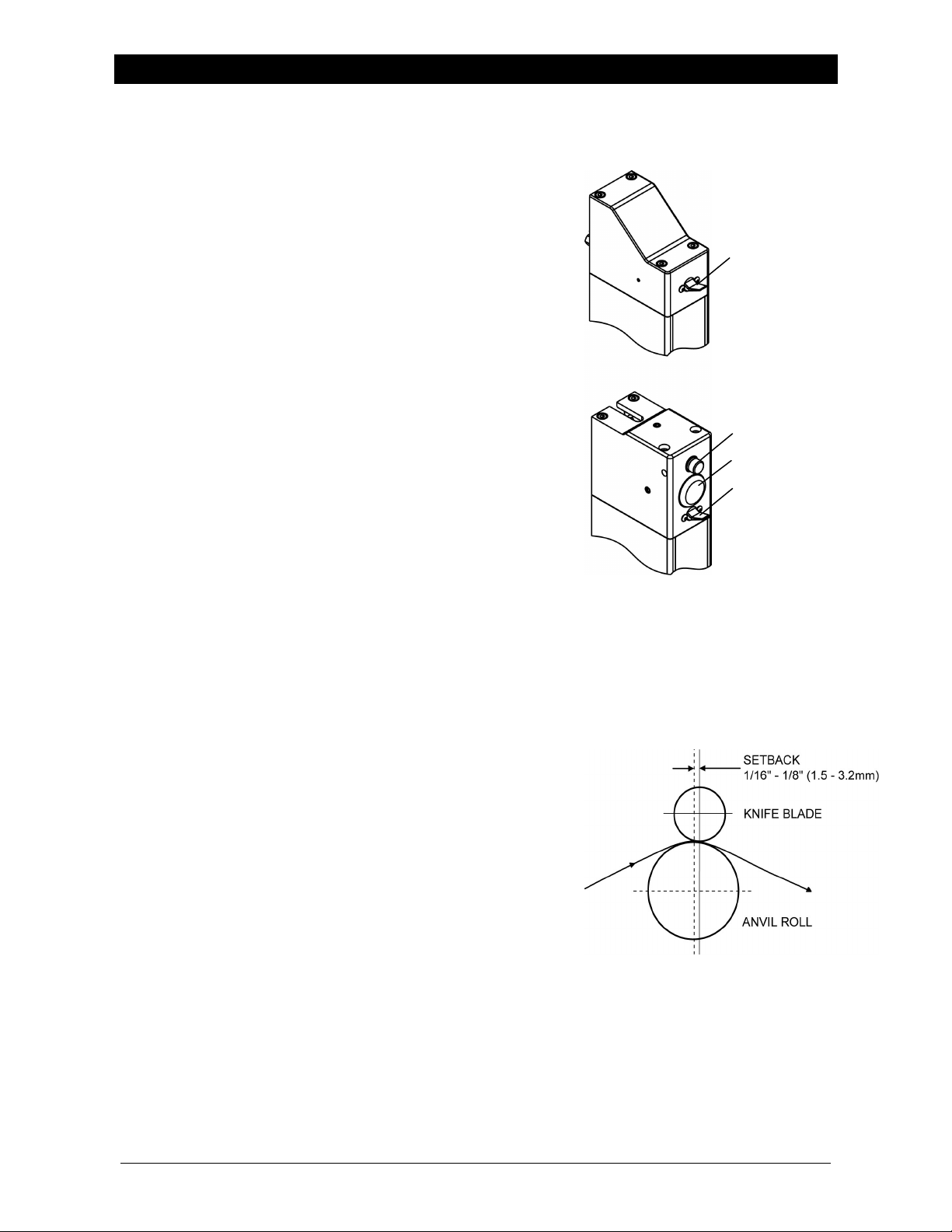
•When configuring crush slitters, it is important that the
centerline through the knife blade be placed slightly
downstream of the centerline through the anvil roll and
parallel to blade cartridge travel. This prevents lateral blade
tracking. The goal is to have a slight castering effect. The
actual offset is not critical; a reasonable offset is between
1/16" to 1/8".
•Tidland-Camas offers design assistance regarding your
Crush Slitting System requirements. (1-800-426-1000)
KNIFEHOLDER
A
CTUATOR SWITCH
KNIFEHOLDER
A
CTUATOR SWITCH
GAUGE
A
IR PRESSURE
REGULATOR
WOR
WR
CLASS II SHOWN
WRAP SLITTING MODE

www.maxcessintl.com Tidland Performance Series Crush Knifeholder MI 612075 1 H
Page 6
WOR – without Regulator and GaugeWR – with Regulator and Gauge
1
8
3
2
5
7
4
14
10
9
6
11
11
7
13
1
12
14
8
6
4
10
9
ORIENTATION
Knifeholder Components
Class I
ITEM DESCRIPTION FUNCTION
1 Control Body Holds blade cartridge
2 Air Pressure Regulator (WR only) Controls knifeholder down force (0-60 psi)
3 Air Pressure Gauge (WR only) Air pressure reference ((0-60 psi)
4 Lock Screw Fastens blade cartridge to control body
5 Safety Lock Latch Assembly Blade cartridge-to-control body locator and safety lock
6 Bellows Prevents foreign matter from entering knifeholder
7 Air Supply Fitting See Air Hose Fitting Chart , page 11.
8 Knifeholder Actuator Switch Down – extends blade cartridge
Up – retracts blade cartridge
9 Knife Blade Lock Latch Stops blade rotation when removing or replacing blade
10 Blade Cartridge Holds knife blade
11 Knife Blade Crush cutter – slits web material
12 Blade Clamp Secures knife blade to blade cartridge
13 Blade Clamp Fasteners Secures blade clamp to blade cartridge
14 Knifeholder Mount Assembly Mounts knifeholder to guide bar
Part numbers for all models begin on page 28.
www.maxcessintl.com Tidland Performance Series Crush Knifeholder MI 612075 1 H
Page 7
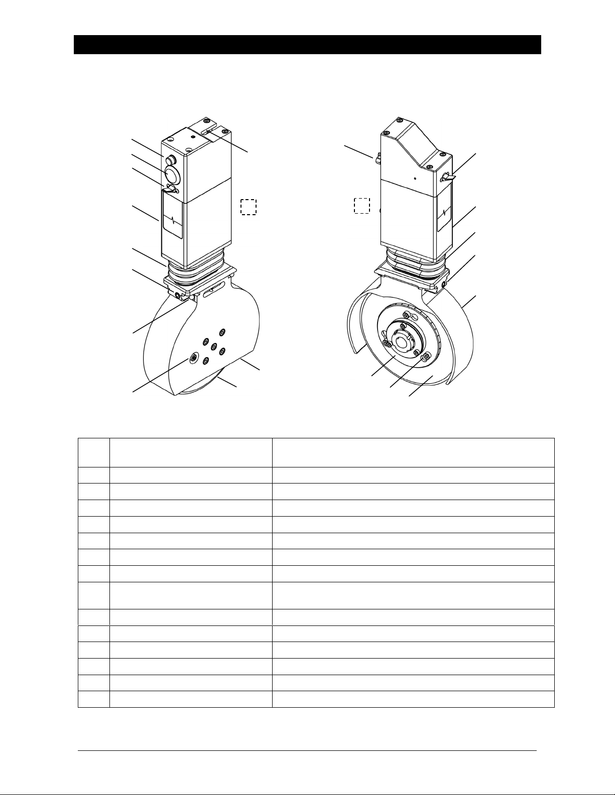
ORIENTATION
Knifeholder Components
Class II and III
ITEM DESCRIPTION FUNCTION
1 Control Body Holds blade cartridge
2 Air Pressure Regulator Controls knifeholder down force (0-60 psi)
3 Air Pressure Gauge Air pressure reference (0-60 psi)
4 Lock Screw Fastens blade cartridge to control body
5 Safety Lock Latch Assembly Blade cartridge-to-control body locator and safety lock
6 Bellows Prevents foreign matter from entering knifeholder
7 Air Supply Fitting See Air Hose Fitting Chart, page 11.
8 Knifeholder Actuator Switch Down – extends blade cartridge
Up – retracts blade cartridge
9 Knife Blade Lock Latch Stops blade rotation when removing or replacing blade
10 Blade Cartridge Holds knife blade
11 Knife Blade Crush cutter – slits web material
12 Blade Clamp Secures knife blade to blade cartridge
13 Blade Clamp Fasteners Secures blade clamp to blade cartridge
14 Knifeholder Mount Assembly See Mount Knifeholder to Guide Bar, p. 17-18
Part numbers for all models begin on page 28.
WR – with Regulator and Gauge WOR – without Regulator and Gauge
1
8
3
2
6
5
11
7
4
14
10
9
7
13
1
12
14
8
6
4
10
11

www.maxcessintl.com Tidland Performance Series Crush Knifeholder MI 612075 1 H
Page 8
A
LIGNMENT BUSHING ASSEMBLY
Do not loosen screws.
KNIFEHOLDER LOWER BODY
BELLOWS
DOVETAIL
A
LIGNMENT ROD
PISTON GUIDE
DOVETAIL LOCK ASSEMBLY
CAUTION! Do not remove rods from dovetail.
A
LIGNMENT ROD BUSHING
PISTON GUIDE ROD BUSHING
ORIENTATION
0° Cant Angle Setting
The 0°cant angle setting on the Alignment Bushing Assembly is factory set using the four
screws at the bottom of the lower body. To maintain the alignment, do not remove or loosen
the screws.
KNIFEHOLDER LOWER BODY
A
LIGNMENT BUSHING ASSEMBLY
Do not loosen screws.
DOVETAIL LOCK ASSEMBLY
EXPLODED VIEW

www.maxcessintl.com Tidland Performance Series Crush Knifeholder MI 612075 1 H
Page 9
ORIENTATION
Crush Slitting Blade Profiles
•These blade profiles should be viewed as reference points in determining the optimum profile for
any given material.
•Smaller tip radii and acute angles result in rapid tip fracture and anvil roll grooving.
•Larger tip radii and included angles require more force to slit.
•To reduce chipping and rapid dulling of blades, it is important to remove burred edges from
resharpened blades.
•Make sure to grind the blade edge smooth to avoid dust formation during the slitting process.
•See also: Knifeholder Supply Pressure vs. Down Force Chart on page 19.

www.maxcessintl.com Tidland Performance Series Crush Knifeholder MI 612075 1 H
Page 10
ORIENTATION
Air Supply System
Tidland Corporation recommends:
•the use of a filtered and regulated pneumatic system to prevent airborne oil or water from
contaminating the knifeholders. Clean, non-lubricated, dry air is required for optimal performance
of the knifeholder.
•the use of individual regulators for each knifeholder for improved blade life and cut quality
performance.
Individual air pressure settings will depend on blade conditions and web material.
Note: The WOR Model with pneumatic mount knifeholder requires two manifolds.
•One supplies the pneumatic mount;
•The other supplies each knifeholder independently for variable air pressure regulation.
(See Air Hose Fitting Chart on page 11.)
Part No. 520984 air filter system components include:
A - Quick exhaust valve with muffler
B - 3-way manual valve with muffler
C - Coalescing filter
D - 5 micron air filter / pressure regulator with gauge
E - 3/8 (9.52mm) supply air lines
Model WOR with pneumatic mount requires two filter systems.
Other manuals for Tidland Performance Series
1
This manual suits for next models
2
Table of contents
Popular Kitchen Appliance manuals by other brands

Tayama
Tayama TYG-35AF instruction manual

AEG
AEG 43172V-MN user manual

REBER
REBER Professional 40 Use and maintenance

North American
North American BB12482G / TR-F-04-B-NCT-1 Assembly and operating instructions

Presto
Presto fountain popper instruction manual

Westmark
Westmark 1035 2260 operating instructions


