Page 2 of 5 pages
If you think there is any shipping damage or missing part(s), please read our after-sales service and return policy as outlined
below.
1. Inspect your order upon delivery for any shipping damage or missing part. If you find a problem you must contact us
within 10 days from receipt of your purchase by calling (562) 802-0680, Monday through Friday, except holidays, between
the hours of 8:30 AM and 5 PM Pacific time. During this telephone conversation, and with your support, we will
determine how to resolve your concern. (Note: Maxford USA Li-Po batteries are sold without warranty and are not
eligible for return or credit.)
2. To request an RMA#, call (562) 802-0680, Monday through Friday, except holidays, between the hours of 8:30 AM to
5 PM Pacific time. If we elect to issue you an RMA#, you must clearly mark this RMA# on the outside of the package.
(No return or exchange will be authorized after 10 days from the date of your receipt of the product; any package delivered
to us without a Maxford USA RMA# is subject to being returned to the sender, as received, with return postage payable
upon delivery.) Returned merchandise must be in its original condition as received from Maxford USA, with no assembly
or modification, in the original packing materials, complete with all manuals and accessories. Return shipping and
insurance charges must be prepaid by you, the buyer.
3. Returned merchandise that is accepted by Maxford USA for credit is subject to a 10% to 20% restocking fee (the final
amount will be determined by Maxford USA upon receipt and examination of the returned merchandise).
Return Address:
Maxford USA RC Model Mfg, Inc.
15247 Texaco Avenue
Paramount, CA 90723-3917
(IMPORTANT: If issue by Maxfor USA RC Mo el Mfg, Inc.,
print the RMA# on the package near the above a ress.)
PARTS LIST
1. Items you must supply to complete the Hughes H-1:
• Receiver/transmitter with a min. of 5 channels for
aileron, elevator, rudder, throttle and retracts.
• 1 ea. retract-servo (HS-65HB, HS-81 or HS-82 MG).
• 6-inch servo-wire extension for retracts.
• Thin cyanoacrylate (CA) adhesive, 5-minute epoxy
glue and Loctite Screw Lock or equivalent compound.
• Masking tape, common hand tools, a black marking pen
(and possibly a piece of 1/16-inch and 3/16-inch
plywood, depending on your choice of retract servo).
2. Items included in the Hughes H-1
retractable landing gear package:
• Light-weight mechanical retractable landing
gear, sized to fit in the Hughes H-1’s wing.
• This illustrated instruction manual.
N
OTE
: The Hughes H-1’s ARF package
contains the retract servo’s pushrods and all
required self-threading screws (except for
the screws supplied with the servos.)
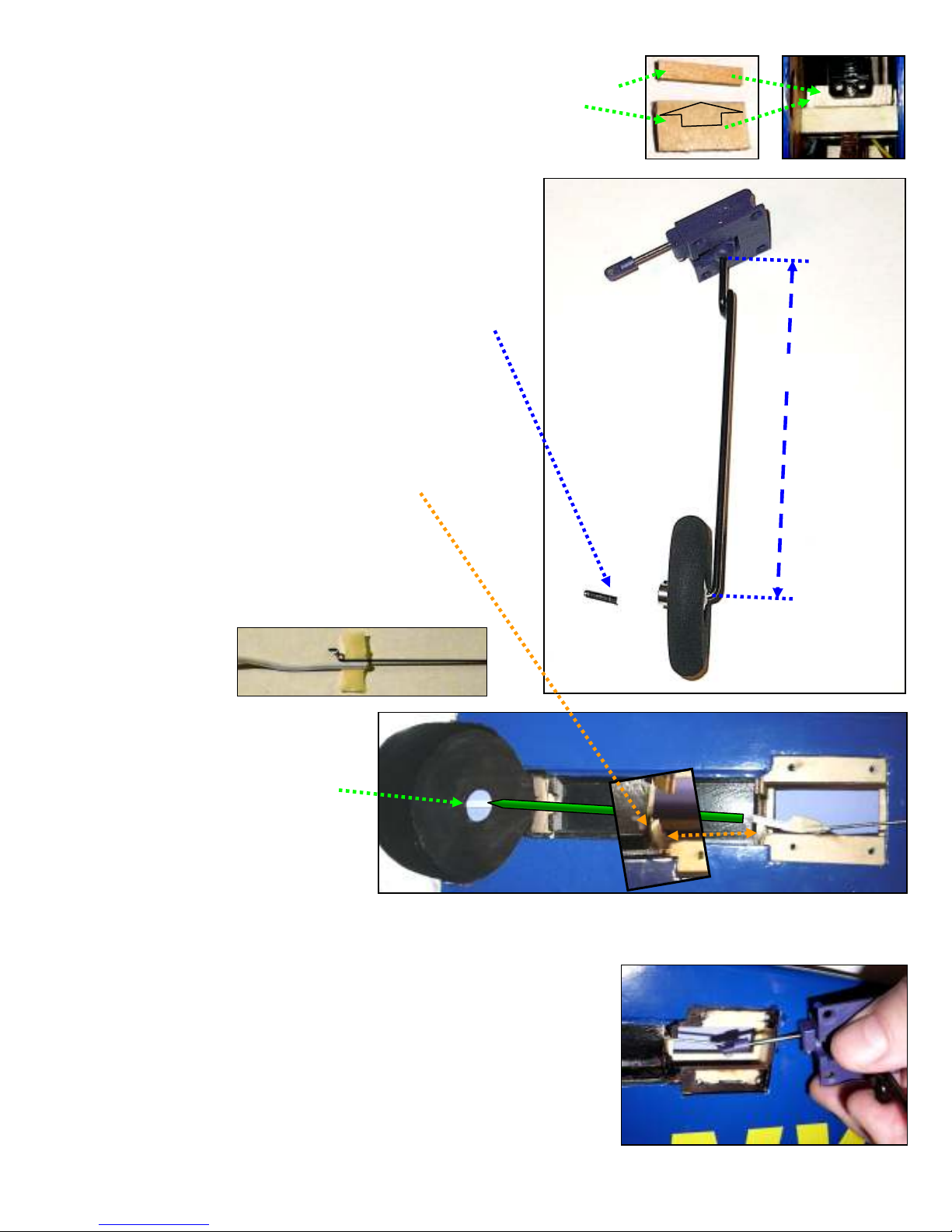
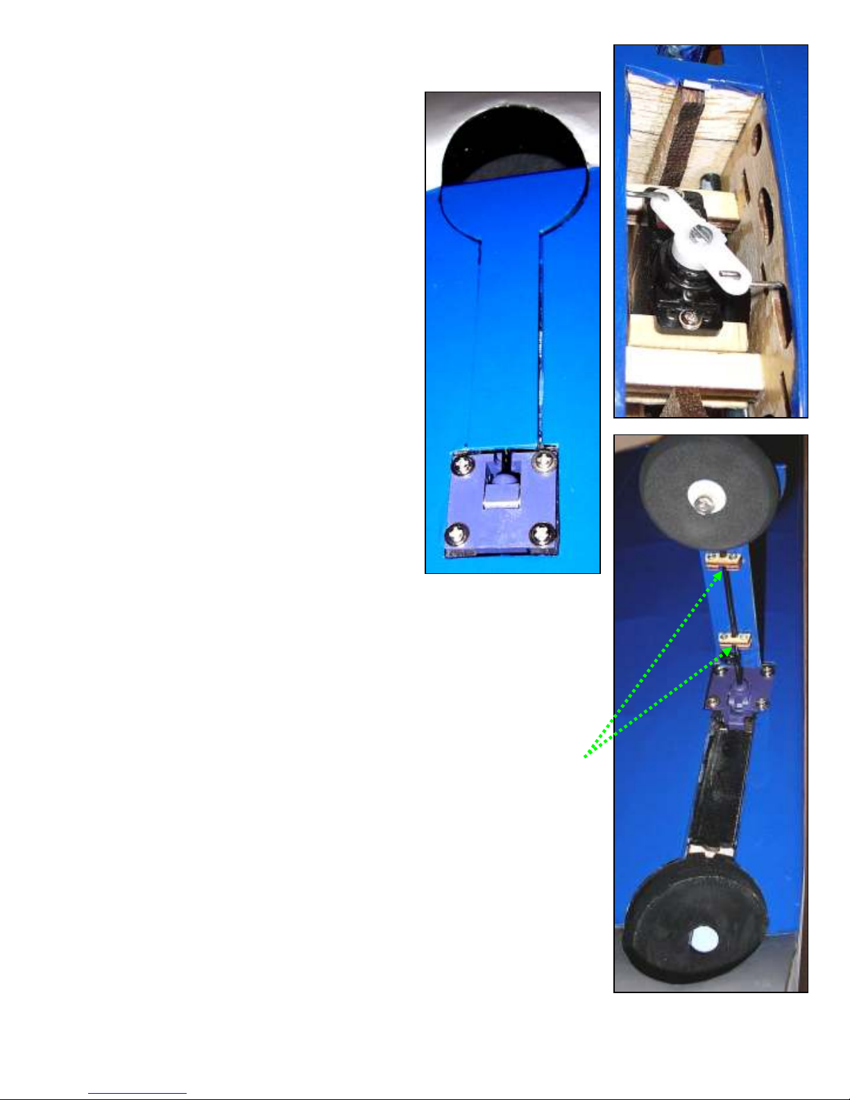
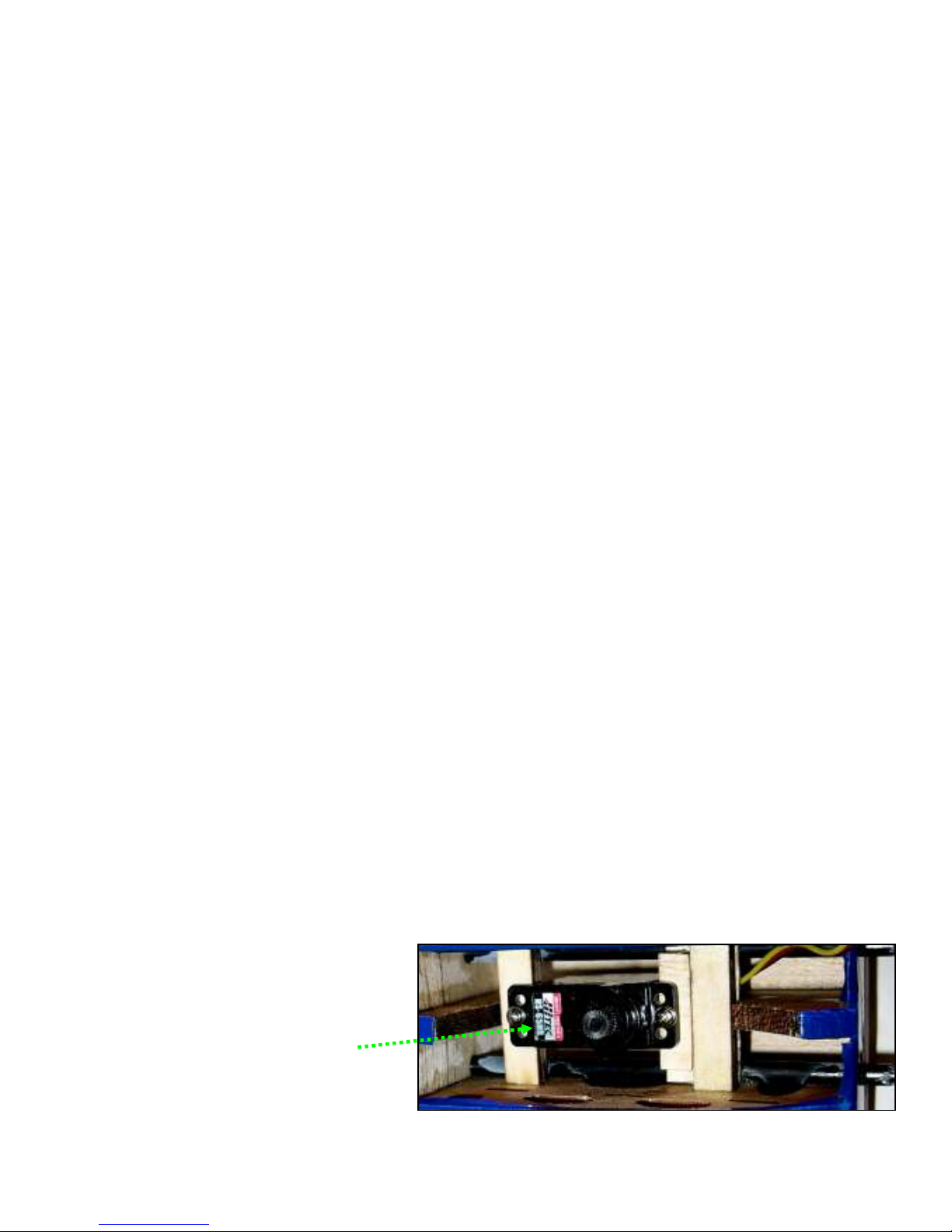
HUGHES H-1 RETRACTABLE LANDING GEAR INSTALLATION INSTRUCTIONS
(Note: The following instructions replace #35 in the instruction manual supplie with the Hughes H-1.)
35.1. Install your retract servo between the
servo mounting rails at the center front of
the H-1’s wing. (NOTE: The space
between the servo rails fits HS-81 and
HS-82 MG servos. If you use of an HS-
65HB or other smaller-sized servo,
reduce the space between the retract
servo rails as follows: Fit and glue a
piece of 1/16-inch plywood under the