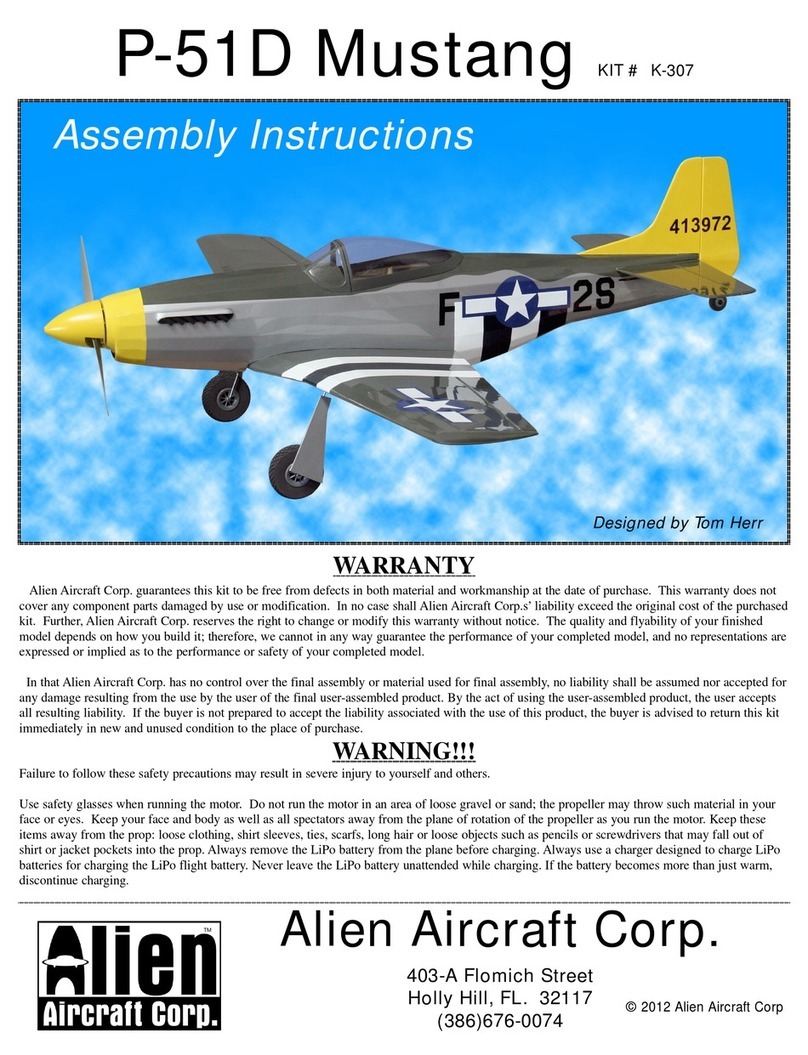
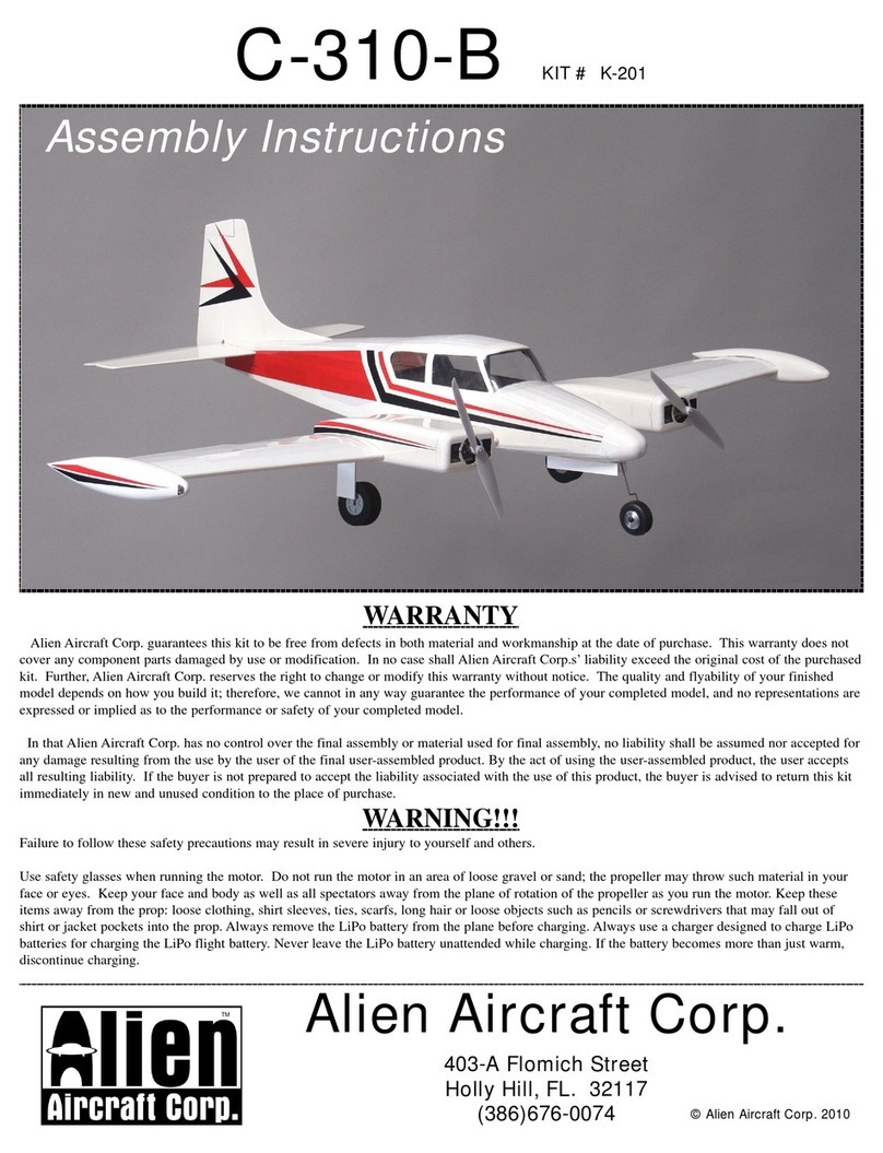
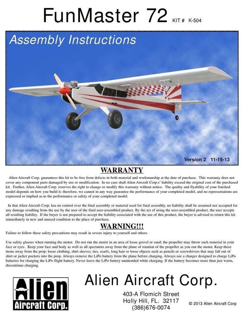
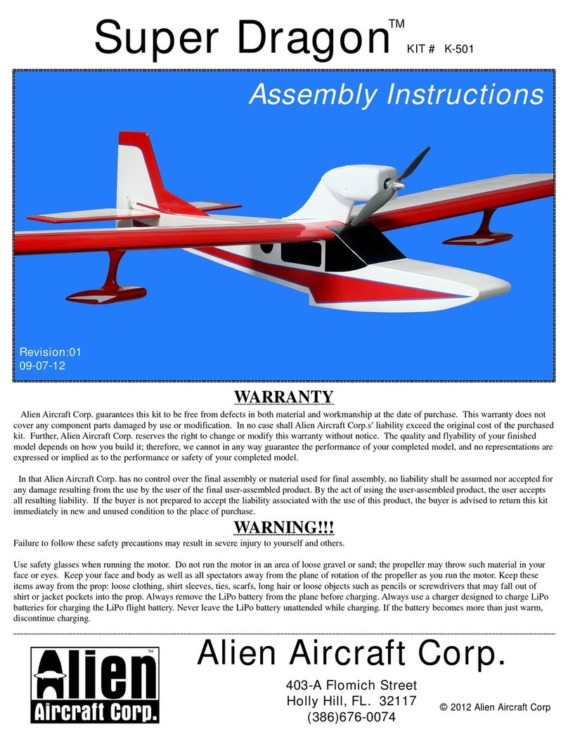
Alien Aircraft Corp ArrowMaster 55 User manual

AlienAircraftCorp.
Manufacturedby:
SigManufacturingCo,Inc.
401 S.FrontStreet
Montezuma,IA.50171
(641)623-5154
ArrowMaster55KIT#K-505
WARRANTY
SigManufacturing Co, Inc.guaranteesthiskit to befreefromdefectsinbothmaterialand workmanshipatthedateofpurchase.Thiswarranty
doesnotcoverany componentpartsdamagedby useormodification.Inno caseshall AlienAircraftCorp.s’liabilityexceedtheoriginalcostofthe
purchasedkit.Further,SigManufacturing Co, Inc.reservestherighttochangeormodifythiswarrantywithoutnotice.Thequalityandflyabilityof
yourfinishedmodeldependson howyoubuild it; therefore,wecannotinanywayguaranteetheperformanceofyourcompletedmodel,and norep-
resentationsareexpressedorimpliedasto theperformanceorsafetyofyourcompletedmodel.
InthatSigManufacturing Co, Inc.hasnocontroloverthefinalassemblyormaterialusedforfinalassembly,no liabilityshall beassumednor
accepted forany damageresulting fromtheusebytheuserofthefinaluser-assembledproduct.Bytheactofusingtheuser-assembledproduct, the
useracceptsall resultingliability.Ifthebuyerisnotpreparedtoaccepttheliabilityassociated withtheuseofthisproduct,thebuyerisadvisedto
returnthiskit immediatelyinnewand unusedconditiontotheplaceofpurchase.
WARNING!!!
Failuretofollowthesesafetyprecautionsmayresult insevereinjurytoyourselfandothers.
Usesafetyglasseswhenrunning themotor.Donotrunthemotorinanareaofloosegravelorsand;thepropellermaythrowsuchmaterialinyour
faceoreyes.Keepyourface and body aswell asall spectatorsawayfromtheplaneofrotation ofthepropellerasyou run themotor.Keepthese
itemsawayfromtheprop:looseclothing, shirtsleeves,ties,scarfs,longhairorlooseobjectssuchaspencilsorscrewdriversthatmay fall outof
shirtorjacketpocketsintotheprop. AlwaysremovetheLiPobatteryfromtheplanebeforecharging. AlwaysuseachargerdesignedtochargeLiPo
batteriesforcharging theLiPoflightbattery.NeverleavetheLiPobatteryunattendedwhilecharging. Ifthebatterybecomesmorethanjustwarm,
discontinuecharging.
AssemblyInstructions
©2016 SigMfgCo, Inc.
Version302-17-16

Notesaboutthelasercutparts
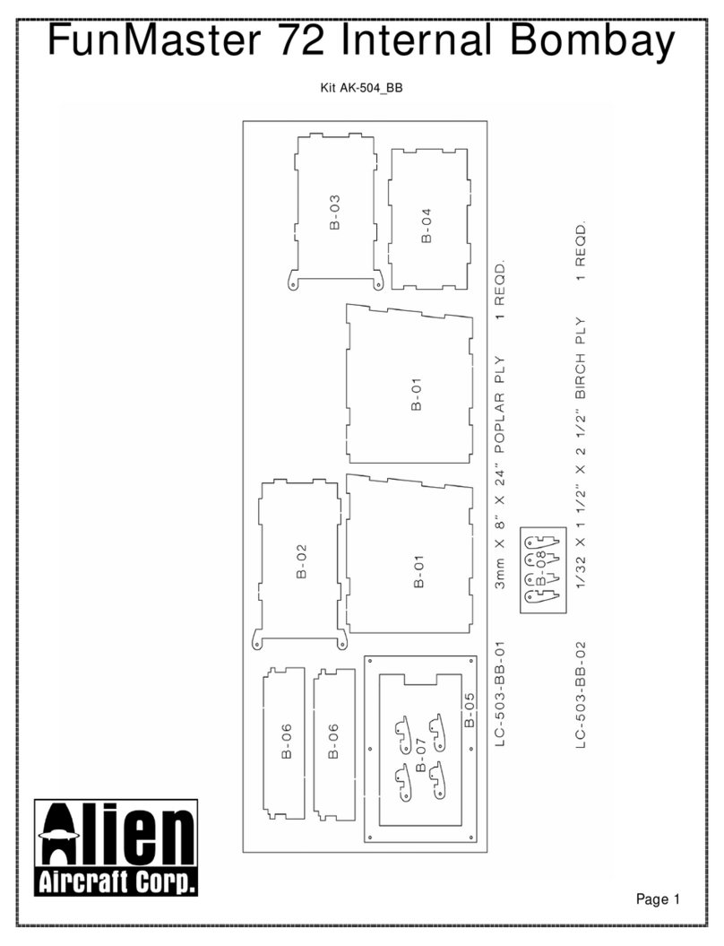
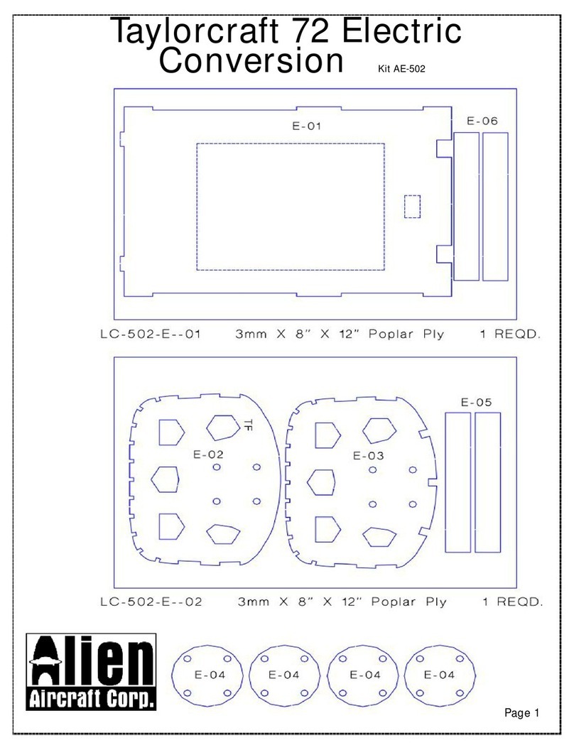
1...Thefirstthingthatyouneedtodo istoidentifyandmarkthepartnumbers onthelasercut
partsusingthedrawingsonthefollowingpagesasaguide.
2...Itispossiblethat severalofthelasercutpartsmay not becompletelycutthrough.Ifthisisthecaseyoucanfreethepartfrom
thesheetquicklyusinganX-acto knife.
3...Theslightdiscolorationontheedgesof thelasercutpartsmayberemovedbylightlysandingtheedgeswith400 gritsandpaper.
KitContents:
Yourkitcontains thefollowingparts. Pleasecheckyourkitforanymissingordamagedpartsbeforestartingconstruction.
WoodBag:
Qty... .Name. ... . ... . ... . ... . ... . ... . ...Description
1. . ...LC-505-01 . ... . ... . ... . ... . ... . ...3mmX4” X24” LaserCutPOPLAR PLY
1. . ...LC-505-02 . ... . ... . ... . ... . ... . ...3mmX8” X24” LaserCutPOPLAR PLY
1. . ...LC-505-03 . ... . ... . ... . ... . ... . ...3mmX4” X24” LaserCutPOPLAR PLY
1. . ...LC-505-04 . ... . ... . ... . ... . ... . ...3mmX8” X24” LaserCutPOPLAR PLY
1. . ...LC-505-05 . ... . ... . ... . ... . ... . ...3mmX4” X24” LaserCutPOPLAR PLY
1. . ...LC-505-06 . ... . ... . ... . ... . ... . ...3mmX8” X24” LaserCutPOPLAR PLY
1. . ...LC-505-07 . ... . ... . ... . ... . ... . ...3mmX8” X24” LaserCutPOPLAR PLY
1. . ...LC-505-08 . ... . ... . ... . ... . ... . ...3mmX8” X24” LaserCutPOPLAR PLY
1. . ...LC-505-09 . ... . ... . ... . ... . ... . ...3mmX8” X24” LaserCutPOPLAR PLY
1. . ...LC-505-10 . ... . ... . ... . ... . ... . ...3mmX8” X24” LaserCutPOPLAR PLY
1. . ...LC-505-11. . ... . ... . ... . ... . ... . ..1/8” X4” X24” Laser CutBALSA
1. . ...LC-505-12 . ... . ... . ... . ... . ... . ...1/8” X4” X24” Laser CutBALSA
1. . ...LC-505-13 . ... . ... . ... . ... . ... . ...1/8” X4” X24” Laser CutBALSA
1. . ...LC-505-14 . ... . ... . ... . ... . ... . ...1/8” X4” X24” Laser CutBALSA
1. . ...LC-505-15 . ... . ... . ... . ... . ... . ...1/8” X4” X24” Laser CutBALSA
1. . ...LC-505-16 . ... . ... . ... . ... . ... . ...1/8” X4” X24” Laser CutBALSA
1. . ...LC-505-17 . ... . ... . ... . ... . ... . ...1/8” X4” X24” Laser CutBALSA
1. . ...LC-505-18 . ... . ... . ... . ... . ... . ...1/8” X4” X24” Laser CutBALSA
2. . ...LC-505-19 . ... . ... . ... . ... . ... . ...3/32” X4” X24” Laser CutBALSA
2. . ...LC-505-20 . ... . ... . ... . ... . ... . ...3/32” X4” X24” Laser CutBALSA
2. . ...LC-505-21 . ... . ... . ... . ... . ... . ...3/32” X4” X24” Laser CutBALSA
2. . ...LC-505-22 . ... . ... . ... . ... . ... . ...3/32” X4” X24” Laser CutBALSA
1. . ...LC-505-23 . ... . ... . ... . ... . ... . ...3/32” X4” X24” Laser CutBALSA
2. . ...LC-505-24 . ... . ... . ... . ... . ... . ...3/32” X4” X24” Laser CutBALSA
1. . ...LC-505-25 . ... . ... . ... . ... . ... . ...3/32” X4” X24” Laser CutBALSA
1. . ...LC-505-26 . ... . ... . ... . ... . ... . ...3/32” X4” X24” Laser CutBALSA
1. . ...LC-505-27 . ... . ... . ... . ... . ... . ...3/32” X4” X24” Laser CutBALSA
1. . ...LC-505-28 . ... . ... . ... . ... . ... . ...3/32” X4” X24” Laser CutBALSA
1. . ...LC-505-29 . ... . ... . ... . ... . ... . ...3/32” X4” X24” Laser CutBALSA
1. . ...LC-505-30 . ... . ... . ... . ... . ... . ...1/16” X4” X24” Laser CutBirchPly
1. . ...LC-505-31 . ... . ... . ... . ... . ... . ...1/32” X4” X12” Laser CutBirchPly
9. . ...TailSheet. . ... . ... . ... . ... . ... . ..1/16” x4” x24” Balsa
3. . ...WingSheet. ... . ... . ... . ... . ... . ..3/32” X4” X24” Balsa
1. ... . .Windshield. ... . ... . ... . ... . ... . ...015” x3” x7” Plastic
Page 2
PlansBag:
Qty. ... . .Name. ... . ... . ... . ... . ... . ... . ... . ... . ..Description
1.. . ... . .K-505 PLANA
1.. . ... . .K-505 PLANB
1.. . ... . .K-505 PLANC
8.. . ... . .MainWingSpars.. . ... . ... . ... . ... . ... . ..1/8” x3/8” x36” Bass
9.. . ... . .WingLeadingEdge&Jig,FuselageStringers,Braces&Fillers........1/4” x1/4” x36” Balsa
8.. . ... . .WingTrailingEdge. . ... . ... . ... . ... . ... . ..3/32” x1” x36” Balsa
5.. . ... . .FuselageStringers.. . ... . ... . ... . ... . ... . ..1/8” x1/4” x36” Balsa
1.. . ... . .UpperJig&Cowl.. . ... . ... . ... . ... . ... . ..3/8” x3/8” x36” Balsa
2.. . ... . .NStruts.. . ... . ... . ... . ... . ... . ... . ... . ..3/16” x3/8” x36” Bass
1.. . ... . .FuselageBraces. ... . ... . ... . ... . ... . ... . ..1/4” Trianglex12” Balsa
Misc. LooseParts
Qty. ... . .Name.. . ... . ... . ... . ... . ... . ... . ... . ... .Description
8.. . ... . .WingLeadingEdgeSheet. ... . ... . ... . ... . ..3/32” x3” x36” Balsa
1.. . ... . .CowlSheet. ... . ... . ... . ... . ... . ... . ... . ..1/4” x2” x36” Balsa
1.. . ... . .CowlSheet. ... . ... . ... . ... . ... . ... . ... . ..1/4” x2” x6” Balsa
2.. . ... . .MainLandingGearL&R... . ... . ... . ... . ..FormedAluminum
2.. . ... . .CabaneStrutsL&R. ... . ... . ... . ... . ... . ..FormedAluminum
1.. . ... . .Tail WheelWire. ... . ... . ... . ... . ... . ... . ..1/16” x6” MusicWire
Hardware Bag
Qty. ... . .Name.. . ... . ... . ... . ... . ... . ... . ... . ... .Description
1.. . ... . .TailwheelBracket.. . ... . ... . ... . ... . ... . ..MoldedNylonBracket
8.. . ... . .“N”StrutFittings.. . ... . ... . ... . ... . ... . ..MoldedNylonStraps
8.. . ... . .TopWing&MotorMountBlindNuts.. . ... . ..6-32 Blind Nuts
4.. . ... . .Cabane... . ... . ... . ... . ... . ... . ... . ... . ..6-32 x1/2” Screws
1.. . ... . .ElevatorJoinerDowel.. . ... . ... . ... . ... . ..1/4” x41/2” BirchDowel
2.. . ... . .WingDowels... . ... . ... . ... . ... . ... . ... .1/4” x1” BirchDowel
2.. . ... . .WingBolts. ... . ... . ... . ... . ... . ... . ... . .1/4-20 x1” NylonScrew
4.. . ... . .ControlHorn.. . ... . ... . ... . ... . ... . ... . ..Aileronand TailLargeControlHorns
22. . ... . .#2 SheetMetalScrews... . ... . ... . ... . ... . .#2X1/2” SheetMetalScrew
4.. . ... . .Tail HornScrews... . ... . ... . ... . ... . ... . ..2-56 x1/2” MachineScrew
4.. . ... . .AileronServo Mounts... . ... . ... . ... . ... . ..3/8” x3/8” x1” Bass
20”. . ... . .BottomWingJointTape. . ... . ... . ... . ... . ..2” x20” DacronTape
48”. . ... . .TopWingJointTape, Elevator&Tailwheel. . ..1” x48” DacronTape
2.. . ... . .AileronHornWedgeBlocks.. . ... . ... . ... . ..3/16” x1/2” x1/2” Bass
8.. . ... . .“N”StrutBlocks... . ... . ... . ... . ... . ... . ..3/8” x3/8” x3/8” Bass
8.. . ... . .“N”Strut. ... . ... . ... . ... . ... . ... . ... . ..4-40 x3/8” MachineScrews
8.. . ... . .“N”Strut. . ... . ... . ... . ... . ... . ... . ... . ..4-40 Blind Nuts
8.. . ... . .AxleNuts. . ... . ... . ... . ... . ... . ... . ... . ..8-32 Nuts
2.. . ... . .Axles. ... . ... . ... . ... . ... . ... . ... . ... . ..8-32 x2” Bolt
2.. . ... . .AxleWashers.. . ... . ... . ... . ... . ... . ... . ..8-32 Washers
Page3

AdditionalItems Required(NotIncludedinKit)
Qty. . ... . .Name.. . ... . ... . ... . ... . ...Description
1... . ... . .CoveringMaterial. ... . ... . ...3Rolls CoveringMaterialPlusTrimColors
17.. . ... . .Tail &AileronHinges. . ... . ...C/AorPinStyleHinges
2... . ... . .Tail Pushrods. ... . ... . ... . ...Dubro30” LaserRods (1pair)(DuBroP/N:500)
2... . ... . .AileronPushrods. . ... . ... . ...12” 2-56 Pushrods (1pair)(DuBroP/N:123)
1... . ... . .Tail L/GCollar... . ... . ... . ...1/16” WheelCollar(DuBroP/N:137)
2... . ... . .MainWheels. ... . ... . ... . ...3-1/2” Wheels (DuBroP/N:350TL)
1... . ... . .Tail Wheel.. . ... . ... . ... . ...1"Tail Wheel(SullivanP/N:100TW)
1... . ... . .Radio.. . ... . ... . ... . ... . ...4ChannelRadiowithReceiver
2... . ... . .Tail Servos.. . ... . ... . ... . ...HiTecHS-311StandardServos orEquivalent
2... . ... . .AileronServos... . ... . ... . ...HiTecHS-311StandardServo orEquivalent
1... . ... . .ThrottleServo... . ... . ... . ...HiTecHS-311StandardServo orEquivalent
1... . ... . .Throttlecabletoservo. . ... . ...DuBroEZConnector(DuBro#121)
1... . ... . .Aileron“Y”Connector. ... . ...6” “Y”Connectortofityourradio
1... . ... . .AileronServo Extension... . ...6” Servo Extensionstofityourradio
1... . ... . .Motor.. . ... . ... . ... . ... . ...2-stroke.65-.90 or4-stroke.70-.95 or15cc Gas
1... . ... . .MotorMount. ... . ... . ... . ...DaveBrownMotorMount(tofityourmotor)
4... . ... . .MotorMounttoFirewall... . ...6-32 x1” MachineScrews(size tofityourmotor)
4... . ... . .MotortoMount.. . ... . ... . ...6-32 x1” MachineScrews(orsizetofityourmotor)
1... . ... . .Propeller. ... . ... . ... . ... . ...13” x5” Propeller(orsize tofityourmotor)
1... . ... . .FuelTank... . ... . ... . ... . ...DubroSquareFuelTank 12 oz(Dubro#412)
1... . ... . .ThrottlePushrod. . ... . ... . ...DubroThrottleCableAssembly(Dubro#3105)
1... . ... . .FuelLine... . ... . ... . ... . ...MediumFuelLine(DuBro#222)
1... . ... . .FoamRubber. ... . ... . ... . ...1/4” FoamRubber(DuBro#513)
1... . ... . .Spinner. . ... . ... . ... . ... . ...DuBro3” Spinner
OptionalItems:
1Pair... . .WheelPants. . ... . ... . ... . ...FiberglassSpecialties#23 WheelPants
4... . ... . .WheelPantNuts. . ... . ... . ...4-40 Blind Nuts
4... . ... . .WheelPantScrews. ... . ... . ...4-40 x3/8” MachineScrews
2... . ... . .AxleNuts... . ... . ... . ... . ...8-32 Nuts(inadditiontotheeightinthekit)
Note:Wedecidednottoputwheelpantsinthekitbecausemanybuilderswouldnotusethem.Andifweput
theminthekittheywouldbevac-formedplastic,whichisflimsyand apaintoassemble.However,wefound
agreatsetofepoxy glasswheelpants fromFiberglassSpecialtiesthatlookgreat,are rugged,andfitperfectly.
Theircontactinfois:
FiberglassSpecialties
15715 AshmoreDr.
Garfield,Arkansas72732
Phone479 359-2429
WebSite:http://www.fiberglassspecialtiesinc.com/
Page 4

Page5

Page 6

Page 7

Page 8

BuildingInstructions: GeneralNote:Covertheplanswithwaxpaperbeforeassembling yourmodel
topreventthepartsfromsticking totheplan.
Note:Theshapeofsomeofthelightning holesinthetail surfaces and rearfuselagehavebeenchangedand maynot
matchthepohtos intheinstructions. However,thishasno impacton theassemblywhichremainsthesame.
BuildingtheTail Surfaces:
1...GlueS-1and S-2togetherasshowntomakethestabilizer. GluetwosetsofS-3and S-4togetherasshownto
maketheelevators.
Page 9

2...Gluetogethertwopiecesof1/16”x4”x
24”balsasheetasshowntomaketheskins
forthetail surfaces.Maketwomoresets for
atotalof3skins.
3...Gluethissheettoonesideofthestabilizer.
Holdflattopreventany warpsortwistswhile
thegluedries.
4...Trim thesheetflushwithS-1/S-2.
Savethecutoffscrappieces.
5...Nowsheetand trim theoppositeside
asyou didthefirst.Holdflattopre-
ventany warps ortwists whiletheglue
dries.Savethecutoffscrappieces.
Page 10

6...GlueR-1and R-2togethertomakethefin.Sheetoneside
ofthefin.Holdflattopreventany warpsortwistswhilethe
gluedries.Trim thesheetand thensheettheothersideand trim.
Holdflattopreventany warpsortwistswhilethegluedries.
7...GlueR-3and R-4togethertomake
therudder. Use1/16”balsatosheet
bothsidesoftheelevators.Use1/16”
balsatosheetbothsidesoftherudder.
8...Jointheelevatorsusing the1/4”x4-
1/2”dowel.Usethestabilizeras a
guidetoestablishtheproperspacing.
Trim thedoweltoachievetheproper
lengthifrequired.
9...Bevelthefrontedgeoftherudderasshownon
theplan,and sand theotheredgesofthefinand rud-
derround.Leavethebottomedges ofthefinthat
will contactthefuselagesquare.
Markthehingelocations and cutthehingeslots.
Temporarilyinstall thehingeswithoutglue.
Page11

10...Bevelthefrontedgeoftheeleva-
torsasshownon theplan,and sand
theotheredges round. Sand thefront
and endsofthestabilizerround.
Leavethebackedgesquare.
Markthehingelocations and cutthe
hingeslots. Temporarilyinstall the
hinges
withoutglue.
11...Cuttwo2”piecesofthe1”nylon tape.Gluethis
tapearound thedowels on eachelevator.
BuildingtheBottomWing:
Covertherightwing planwithwaxpapertopreventthepartsfromsticking totheplan.
12...Cutthefollowing pieces:four3/32”x3”x36”balsasheet,two1/4”sq. x36”balsasticks,four1/8”x3/8”x
36”Basssticks,and four3/32”x1”x36”balsastripstoalengthof30”.Sanethecutoffpieces.
13...GluetwoB-12’stogethertomakeonewing tip.
Repeattomakeasecond wing tip.
14...Gluethefourbottomwing joiners(B-Joiner)
together.
Page 12

15...GluetwoB-8’stogether.Repeattomakeasecond assembly.
16...GluetwoB-7’stogether.Repeattomakeasecond assembly.
Note:oneedgeoftheB-7’shasaslightangle. Besurethatthis
angleislinedup on thetwopieceswhenyou gluethemtogether.
17...GluetwoB-9’stogether.Repeatto
makeasecond assembly.
18...GluetheB-1A’s totheB-1and B-2
ribs.Besuretomakealeftand right
hand assemblyasshown.
BuildingtheRightBottomWing:
19...Pinoneofthe1/8”x3/8”x30”bassmainsparstotheplan.Theinboardend shouldextend alittlepastthecen
-
terlineofthewing. Theotherend will extend pastthelastribatthewing tip.This excesswillbetrimmedofflater.
Page 13

20...Pinand glueribB-2intoposition
on thebottomspar. Itshouldbe90
degreestothebuilding board.The
B-1Ashouldface towardtheinboard
end ofthewing.
21...Glueshearweb“B-A”intoposi-
tion againstthefrontface ofthe
lowersparand againstribW-2as
shownon theplan.
Thesmall“X”on theshearweb
marks thetop outboardcorners ofthe
shearweb.
22...Pinand glueribB-1intoposi-
tion.Thetop oftheribshouldangle
slightlytowardthewing tipand bein
full contactwiththeshearweb.
Page 14
x

23...GluetheB-7assemblytothefrontofribs
B-1and B-2. Theanglededgeisagainstthe
W-1rib.Itshouldbeflushatthetop and bot-
tomoftheribs.
24...Pinand glueribsB-3,B-
4’s,B-5and B-6intoposition
on thespar.Theyshouldbe
90 degreestothebuilding
board.
25...Gluethetop mainspar
intoposition.
26...Place thelower3/32”x
1”x30”trailing edgesheet
intoposition intheslotsinthe
wing ribs. Itshouldbefully
seatedintheslotsand cen-
teredleftand right.When
properlypositioned,gluethe
trailing edgetotheribs.The
endswill bealittlelong and
will betrimmedflushwiththe
end ribslater.
Page 15

27...Gluethe1/4”sq. x30”balsa
leading edgeintoposition. The
inboardend shouldbeflushwith
thefaceofribB-2and otherend
shouldextend pastribB-6.
28...Position and glueoneB-9
assemblyintoplace betweenribs
B-3and B-6atthebackofthe
wing.Itshouldbetightagainst
thebackofribs W-3,W-4and
W-5.Trim theendsifneededfor
atightfit.
29...Gluetheremaining shear
websB-B,B-C,B-D,B-E, B-F,
and B-Gintoposition.Trim the
endstogettheproperfit ifneed-
ed.
30...Insertapiece of3/32”x3”x
6”balsaleftoverfromstep11
intotheslots inwing ribs B-1
through B-3asshown.Theout-
boardend shouldbeflushwithrib
B-3.Theinboardwillbelong and
extend pasttheB-1rib.Gluethe
sheettotheribsand whenthe
glueis dry,trimthebackedgeoff
flushwiththeend oftheribs.
Page 16

31...Gluetheupper3/32”x1”x30”
trailing edgetothetop ofthewing.
Thebackedgeshouldbeflushwith
therearface oftheB-9assembly.
32...Trim and sand ataperon B-8as
shownon theplan.
33...GlueB-8betweenribsB-1and
B-2atthetrailing edgeofthewing.
34...Glueapiece of3/32”x3”x6”
balsaleftoverfromstep11onto
wing ribsB-1through B-3asshown.
Theoutboardend shouldbeflush
withribB-3.Theinboardwill be
long and extend pasttheB-1rib.
Gluethesheettotheribsand when
theglueis dry,trim thebackedgeoff
flushwiththelowerpieceofsheet.
Page17

35...Trim 1/4”fromoneedgeof
3/32”x3”x30”balsasheetsto
makeit2-3/4”wideasshown.
Savethe1/4”piecetomakethecap
stripslater.
36...Position the3/32”x2-3/4”x
30”leading edgesheetagainstthe
leading edgeasshown.Theout-
boardend shouldbeflushwiththe
B-6rib.Centerit leftand rightso
it extendsslightlypasttheB-1rib
attheinboardend and slightlypast
theB-6ribattheoutboardend.
Whenpositionedproperly,gluethe
sheettotheleading edgeonly.
37...Moistentheoutsideofthe
leading edgesheetwithanammo-
niabasedglasscleanersuchas
Windex.Allowit tosoakinfor
severalminutes. Rollthesheet
backand gluethoroughlytothe
ribsand mainspar.
38...Cuttwopieces 6”long from
oneofthe3/32”x4”x24”balsa
sheets.Useoneofthesepieces to
sheettheinboardend ofthewing
betweenribsB-1and slightlypast
B-3.Trim thewidthtofit between
theleading edgesheetand the
trailing edgesheet.Glueintoposi-
tion.
Page 18

39...Cut3/32”x1/4”widestrips from
theleading edgecutoffascapstrips
and glueintoposition on top oftheB-
4,B-5and B-6ribs. Thecapstrips
shouldbecenteredon theribsexcept
forB-6.TheB-6capstripshouldbe
flushwiththeoutboardface oftherib
and extend inboard.Additionalpieces
canbecutfromoneofthe3/32”x4”
x24”sheetsifneeded.
40...Removethewing fromtheplan.
Removethesupporttabsfromthe
backoftheribs.
41...Pinthe1/4”sqx36”balsasup-
porttotheplanintheposition shown
on theplan. Pinthewing backinto
position on theplanand supportwith
thelowersideup.
42...Trim 1/4”fromoneedgeof3/32”
x3”x30”balsasheets tomakeit 2-
3/4”wideasshown. Savethe1/4”
piece tomakethecapstrips later.
Usethispiece tosheetthelowerlead-
ing edgeasyou didthetop.Besure
thatthewing isheldstraightsoyou
do notinduce atwistwhileinstalling
this sheet.
43...Usetheother6”long piecefrom
step37 tosheettheinboardend ofthe
wing betweenribs B-1and slightly
pastB-3.Trim thewidthtofit
betweentheleading edgesheetand
thetrailing edgesheet.Glueinto
position.
Page 19

44...Position and gluepartB-10 intoposition on the
firsttwoB-4ribsas shown. Thewideedgefaces
outboard. Centerit leftand rightwithanequal
amountofoverhang on eachend.
45...Cut3/32”x1/4”widestrips fromtheleading
edgecutoffas capstrips and glueintoposition on
top oftheB-4,B-5and B-6ribs. Thecapstrips
shouldbecenteredon theribsexceptforB-6. The
B-6capstripshouldbeflushwiththeoutboardface
oftheriband extend inboard.
46...GluetheB-11’sintoposition on theinsideof
partB-10 inthelocations shownon theplan.Align
theholesinthesepartswiththeholes inB-9.
47...Trim thesheet,spars &leading edgeflushwith
theribson bothendsofthewing. Sand theleading
edgeofthewing round tomatchtheprofileshown
on theplan.
Page 20
This manual suits for next models
1
Table of contents
Other Alien Aircraft Corp Toy manuals

Alien Aircraft Corp
Alien Aircraft Corp Taylorcraft 72 User manual

Alien Aircraft Corp
Alien Aircraft Corp K-501 User manual

Alien Aircraft Corp
Alien Aircraft Corp FunMaster 72 User manual

Alien Aircraft Corp
Alien Aircraft Corp P-51D Mustang User manual

Alien Aircraft Corp
Alien Aircraft Corp K-308 User manual

Alien Aircraft Corp
Alien Aircraft Corp C-310-B User manual

Alien Aircraft Corp
Alien Aircraft Corp Hornet K-107 User manual

Alien Aircraft Corp
Alien Aircraft Corp FunMaster 72 K-504 User manual