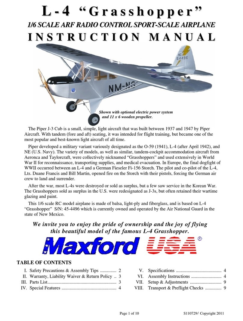
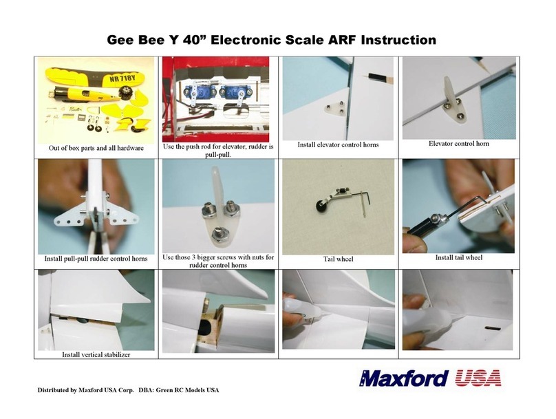
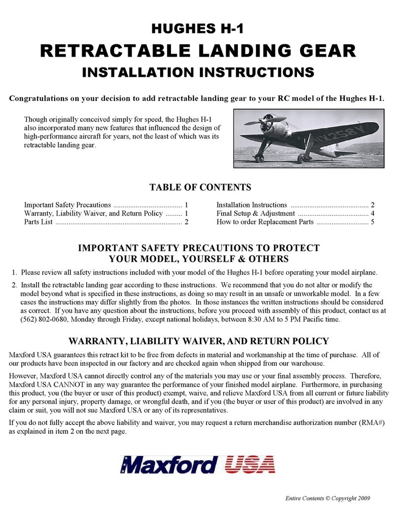
Maxford Nieuport 28 User manual

/
I E U P O R T 2 8
ELECTRIC-POWERED ARF R/C SEMI-SCALE SPORT-FLYER
ISTRUCTIO MAUAL
The Nieuport 28 was the first aircraft to see service in any American fighter squadron.
Nonetheless, the Nieuport 28 was a French iplane fighter designed y Gustave Delage
and uilt y Nieuport, also known as Nieuport-Delage, a French airplane company
famous for racers efore World War I and fighter aircraft during World War I and
etween the wars.
Retaining many of the Nieuport 17’s est features, the Nieuport 28 was a lightly uilt,
highly maneuvera le fighter: It had a more powerful engine, carried twin synchronized machine guns, its ailerons were fitted
only to the lower wing, and it had two-spar wings – top and ottom, in place of the earlier Nieuport types’ sesquiplane (a
iplane with one long wing and one short one a ove or elow it).
By the time the Nieuport 28 ecame availa le in early 1918, it was already considered “surplus” from the French point of
view. Their SPAD S.XIII was a superior aircraft in most respects and had already ecome firmly esta lished as the standard
French fighter.
When the Nieuport 28 was offered to the United States, it was immediately accepted y the American Expeditionary Force,
and 297 Nieuport 28s were put into service in the 27th, 94th, 95th and 103rd Aero Pursuit Squadrons.
American pilots Lieutenant Quentin Roosevelt (who was the youngest son of former President Theodore Roosevelt) and 26-
victory American ace Captain Eddie Ricken acker were among those who flew a Nieuport 28.
This model of the Nieuport 28 is an almost-ready-to-fly semi-scale sport-flyer ARF designed for RC pilots who appreciate the
skill and artistry that comprised the making and flying of World War I aircraft. This model com ines scale appearance with the
ease of transport and flying characteristics which have made 40-inch wingspan EP models so very popular among many sport/
scale RC airplane enthusiasts. Constructed mainly of laser-cut alsa and light ply, this model is finished with a Mylar film
covering patterned after the "Hat in the Ring" aircraft flown y the 94th Aero Squadron’s ace Eddie Ricken acker (a replica of
which may e seen at “The Great War Flying Museum” at the Brampton Airport approximately 30 minutes northwest of
Toronto, Canada).
We invite you to enjoy the pride of ownership and the joy of flying
this beautiful model of the famous ieuport 28.
Page 1 of 12 S101118 / Copyright 2010
Captain Eddie Ric enbac er
Lieutenant Quentin Roosevelt
Shown with optional detail upgrade pac age

/
TABLE OF COTETS
I. Important safety precautions ............................. 2
II. Warranty, lia ility waiver, and return policy .... 2
III. Specifications .................................................... 3
IV. Special features .................................................. 3
V. Parts List ............................................................ 4
VI. Assem ly instructions ................................. 4
VII. Setup and adjustments ............................... 11
VIII. Preflight checks ......................................... 11
I. IMPORTAT SAFETY PRECAUTIOS TO PROTECT YOUR MODEL, YOURSELF & OTHERS:
1. This product should not e considered a toy, ut rather a sophisticated, working model that functions much like
a full-scale airplane. Because of its performance capa ilities, this product, if not assem led and operated cor-
rectly, could cause injury to you or spectators and damage to property. Maxford USA provides you with a high-
quality, thoroughly tested model airplane kit with assem ly instructions. However, the quality and capa ilities
of your finished model airplane depend on how you uild it, and your safety depends on how you use and fly it.
Any testing or flying of this model airplane is done entirely at your own risk.
2. Assem le the model airplane according to these instructions. We recommend that you do not alter or modify the
model eyond the assem ly options covered in these instructions, as doing so may result in an unsafe or un-
worka le model. In a few cases the instructions may differ slightly from the photos; in those instances the writ-
ten instructions should e considered as correct. If you have any question or concern a out these instructions,
efore you proceed with assem ly of this product, contact us at 562-529-3988 (Monday through Friday, except
national holidays, etween 9 AM to 5 PM Pacific time).
3. It is your responsi ility to install the R/C system and other components in such a way that this model airplane
passes all applica le safety/range tests and that the power system and controls operate correctly and smoothly.
4. Recheck the operation of this model airplane efore every flight to ensure that all equipment is still operating
correctly and that the model has remained structurally sound. Also, efore every flight check all electrical
and/or structural connections; do not fly without replacing any that you find damaged or worn.
5. If you are not an experienced R/C pilot or have not flown this type of model efore, we strongly recommend
that you get the assistance of an experienced R/C pilot.
6. Throughout the lifetime of this model, use only the Maxford USA-recommended or same-sized motor and a
new or well-maintained R/C radio system and atteries recommended y the maker of the motor and radio sys-
tem.
7. While this kit has een flight-tested to meet or exceed our rigid performance and relia ility standards in normal
use, if you plan to perform any extremely high-stress flying, such as racing or advanced aero atics, or if you
plan to install a larger power system than specified, you (the uyer or user of this product) are solely responsi le
for taking any and all necessary steps to reinforce the high-stress points and/or su stitute hardware that is more
suita le for such increased stresses.
II. WARRATY, LIABILITY WAIVER, AD RETUR POLICY:
Maxford USA guarantees this kit to e free from defects in material and workmanship at the time of purchase.
All of our products have een inspected in our factory and are checked again when shipped from our ware-
house.
However, Maxford USA cannot directly control the materials you may use nor your final assem ly process.
Therefore, Maxford USA can NOT in any way guarantee the performance of your finished model airplane. Fur-
thermore, in purchasing this product, you (the uyer or user of this product) exempt, waive, and relieve Max-
ford USA from all current or future lia ility for any personal injury, property damage, or wrongful death, and if
you (the uyer or user of this product) are involved in any claim or suit, you will not sue Maxford USA or any
of its representatives.
If you do not fully accept the a ove lia ility and waiver, you may request a return merchandise authorization
num er (RMA#) as explained in item 2 on the following page.
If you think there is a missing, damaged or unsatisfactory part, please read our after-sales service and return
policy on the following page.
Page 2 of 12 S101118 Copyright 2010

/
1. Inspect your order upon delivery for any missing, damaged or unsatisfactory part(s). If you elieve there is a
pro lem, you must call us at 562-529-3988 (Monday through Friday except holidays, etween the hours of
9 AM and 5 PM Pacific time) efore you egin assem ly and within 10 days from receipt of your purchase.
During this telephone conversation, and with your support, we will determine how to resolve your concern.
2. To request a return merchandise authorization num er (RMA#), call 562-529-3988 (Monday through Friday
except holidays, etween the hours of 9 AM to 5 PM Pacific time). If we elect to issue you an RMA#, you
must clearly mark this RMA# on the outside of the package. (No return or exchange will e authorized after
10 days from the date of your receipt of the product; any package delivered to us without a Maxford USA
RMA# is su ject to eing returned to the sender, as received, with return postage paya le upon delivery.) Re-
turned merchandise must e in its original condition as received from Maxford USA, with no assem ly or
modification, in the product’s original packing materials, complete with all manuals and accessories. Return
shipping and insurance charges must e prepaid y you, the uyer.
3. Returned merchandise that is accepted y Maxford USA for credit is su ject to a 10% to 20% restocking fee
(the final amount will e determined y Maxford USA upon receipt and examination of the returned mer-
chandise).
Return Address:
Max ord USA RC Model M g., Inc.
15247 Texaco Ave.
Paramount, CA 90723
IMPORTANT: Print the RMA# issued y Maxford USA
on the package near the a ove address.
III. SPECIFICATIOS:
Wingspan ........................................................................................................... 40-inches
Wing Area ......................................... 326 sq. inches (com ined, top and ottom wings)
Length .................... 33-inches (includes prop. and spinner-nut on recommended motor)
ARF weight .......................................................................................... 1 pound 7 ounces
Flying weight (with motor, ESC, 2100 attery and radio system) ...... 2 pounds 2 ounces
Motor (Not included) .... 277 Watt / 1,280 RPM per Volt (Uranus 28309 or equivalent)
ESC (Not included) ...................................................... 25A (Uranus 25A or equivalent)
LiPo Battery (Not included) ........................................ 11.1 V / 1300 to 2100 mAh, 20C
Propeller (Not included) .............................................................................. Slow Fly 9x6
Radio system (Not included) ....................... Minimum of 4 channels with 3 mini-servos
(Maxford USA ES08A Mini Servo or equivalent)
(All dimensions and weights are approximate)
IV. SPECIAL FEATURES OF THIS ARF IEUPORT-28:
• 9-cylinder dummy engine is visi le within the pre-painted fi erglass cowl.
• Windshield and scale machine guns are included.
• Airframe assem lies are pre-finished with Mylar covering material.
• The fuselage, wings and empennage are jig-assem led laser-cut alsa and
plywood.
• Motor’s mounting position is adjusta le to fit most popular motors.
• Aileron linkages are fully concealed.
• Steera le tail wheel.
*
*
Page 3 of 12 S101118 Copyright 2010

/
• Optional detail upgrade package (availa le separately):
windshield frame; cockpit coming; dummy fuel-system
venturi; engine air intake tu e; wheel covers; and pre-
painted 1/8 scale WWI pilot figure.
V. PARTS LIST:
1. Items you must supply
• Epoxy, cyanoacrylate (CA) and silicone adhesives, masking tape, a drill or high-speed rotary tool, and a few
common hand tools (such as long-nosed and diagonal or side-cutter pliers, etc.).
• Electric power system (motor, electronic speed control, LiPo attery and your choice of solder-connectors)
and Slow Fly 9x6 propeller.
• Three(3) servos (Maxford USA ES08A or equivalent mini-size servos, 23.56mm x 11.56mm x 20.42mm,
weighing approx. 8g / 0.28 oz each) and a 4-channel radio control system.
• Optional: Accessory-upgrade package (including windshield frame, wheel covers, cockpit coming, dummy
fuel-system venturi, engine air intake tu e, and prepainted 1/8 scale WWI pilot figure).
2. Included items
• Fully precovered fuselage, wing panels, vertical and horizontal sta iliz-
ers, rudder and elevator, with a full set of insignia and marking decals.
• Windshield, prepainted fi erglass cowl, and plastic turtle-deck cover.
• Wing attachment olt, wing and tail wires and all related ca ane, strut
and wing wire connection hardware.
• Precut hinge slots and CA hinges.
• Aileron, rudder and elevator pushrods and linkages, with precut mount-
ings for the rudder and elevator servos and with all related control horns
and pushrods.
• Pre-formed steel rod main landing gear with ru er wheels and mount-
ing hardware and pre-installed wooden fairings.
• Steera le tail wheel assem ly with mounting hardware.
• Hook and loop attery-strap material and all required hardware except
those items normally supplied with the servos and motor.
• This detailed, illustrated instruction manual.
VI. ASSEMBLY ISTRUCTIOS:
1. Test fit the horizontal stabilizer on its platform, then remove the Mylar covering from the horizontal sta where
it will e glued to the platform.
2. Using 5-minute epoxy, secure the horizontal sta . fully
forward on its platform at the rear of the fuselage; efore
this epoxy thickens, make sure the horizontal stabilizer
is aligned at right angles to the fuselage and adjust the
horizontal sta ilizer so it is centered on the fuselage, then
remove any excess epoxy.
3. Insert the elevator’s CA hinges in their precut slots in the
elevator and in the horiz. sta ilizer, then apply thin CA
adhesive to each of the elevator’s CA hinges to secure
the elevator to the horizontal stabilizer.
Page 4 of 12 S101118 Copyright 2010

/
4. Test fit the vertical sta ilizer in its slot at the center of the horiz. sta . to make certain
the rear of the vertical sta aligns with the rear of the fuselage. Remove the Mylar cov-
ering from the vertical sta ilizer that will e ‘ uried’ inside the slot in the horizontal
sta ilizer, and secure the vertical stabilizer into its slot with 5-minute epoxy.
5. At each side of the fuselage’s tail, use the straight end of a rudder or elevator pushrod
to poke holes through the Mylar that is covering the openings or the preinstalled
rudder and elevator’s pushrod tubes.
6. From inside the fuselage, insert the rudder’s pushrod (which is slightly longer
than the elevator’s pushrod, and exits at the right-rear side of the fuselage) until it
is a out halfway into its preinstalled tu e. Mount a servo arm on your rudder servo
and attach the Z- ent-end of the pushrod to your rudder servo.
Then, while continuing to slide the rudder’s pushrod into its tu e, guide your rud-
der servo into position in the preinstalled servo tray inside the fuselage. Secure
your rudder servo into the servo tray with the servo mounting screws provided
with your servo.
7. Repeat the a ove procedure for the elevator’s pushrod and servo.
8. Test fit (and make mounting-holes for) the supplied rudder and elevator con-
trol horns in-line with their pushrods. Apply thick CA adhesive to secure the
control horns to the rudder and elevator.
9. Slide a plastic pushrod ‘keeper’ onto the elevator’s pushrod. Center the
elevator’s servo, and apply masking tape to hold the elevator’s surface neu-
tral/centered. Using pliers, make a sharp 90-degree end in the pushrod where
it needs to enter the elevator’s control horn. With the pushrod ent at the cor-
rect length, secure the elevator’s pushrod to the elevator control horn with the
plastic pushrod ‘keeper’ and cut off and discard the extra pushrod wire.
10. Slide the tail wheel onto the tail-wheel wire strut and secure the tail wheel
with the provided wheel collar and set screw.
11. Slide the tail wheel strut fully through the hole in the end
of the aluminum tail wheel mounting racket. Test fit the
tail wheel’s wire strut at the trailing edge of the vertical
sta ilizer and the fuselage, and secure the tail-wheel as-
sembly to the ottom of the fuselage with two provided
wood screws. (Use thin CA adhesive to reinforce these
two holes for their screws.)
12. Test fit the free/‘top’ end of the tail wheel strut into the
predrilled hole in leading edge of the rudder. Apply a
small da of 5-minute epoxy to the end o the tail-
wheel-strut’s wire and insert the wire into the hole
in the rudder. Before the epoxy thickens, use two(2) CA
hinges to attach the rudder to the vertical sta ilizer and
apply thin CA adhesive to the CA hinges and use mask-
ing tape to hold the tail wheel strut’s wire in alignment
with the rudder until the 5-minute epoxy cures.
13. Using pliers, attach one end of a spring to the loop on the 21-inch wire (the wire which does not have a loop
on its other end), then secure the loop under the front screw in the tail wheel racket as shown.
Page 5 of 12 S101118 Copyright 2010
Rudder
Rudder

/
14. Using the point of a needle or other sharp instrument, open a hole in the Mylar that covers oth ends of the two
precut/rein orced openings in the horizontal stabilizer and the single precut/rein orced opening in the verti-
cal stabilizer. Guide the free end of the 21-inch wire through the nearest precut/reinforced opening in the hori-
zontal sta ilizer; through the nearest precut/reinforced opening in the vertical sta ilizer; through the nearest pre-
cut/reinforced opening in the other end of the horizontal sta ilizer; and guide it toward the loose end of the spring.
15. In this step, tighten the wire to slightly expand the spring and secure the wire to the spring as follows: a) Slide a
crimp-tu e onto the end of the wire; ) Pass the end of the wire through the end of the spring; c) Bring the end of
the wire ack into and through the crimp-tu e; d) Pull the wire to shorten its length and expand the spring;
e) Slide the crimp-tu e toward the spring to adjust the desired size of the loop in the end of the wire; and f) Use
pliers to squeeze and crimp the tu e onto the wire, then cut off and discard the extra wire.
16. Test fit the aileron torque rods in their predrilled holes in the leading edge
of each aileron. Apply a small da of 5-minute epoxy to the end of the rods
and insert them into their holes in the ailerons. Before the epoxy thickens,
insert three(3) CA hinges in each aileron and, using thin CA, secure the
ailerons to the wing. Using masking tape, hold the torque rods in alignment
as the epoxy cures.
17. Drill guide-holes in the supplied hardwood blocks and
attach your aileron servo to the locks with the mount-
ing screws provided with your servo. Use 5-minute ep-
oxy to secure the locks (and aileron servo) to the wing.
18. Center your aileron servo, then attach its output arm.
Attach an aileron horn to each torque rod. Using the
supplied aileron pushrods and linkages and the
Z- ends in the end of each pushrod, attach the aileron
pushrods to the aileron servo’s output arm as shown.
19. Slide a plastic pushrod ‘keeper’ onto each of the aileron
pushrods and make a sharp 90-degree end in the push-
rods where each needs to enter its control horn (the same as you did
for the rudder’s and elevator’s pushrods).
20. With the aileron’s pushrods ent to the correct length, secure them
to their control horns with the keepers and cut off and discard the
extra wire from each aileron pushrod.
21. Ensure the wing-dowel is securely glued, with approx. 1/4-inch exposed from its opening at the center of the
lower wing’s leading edge.
22. Use four(4) swivels, coil springs and 10 3/8-inch
wires to prepare four wing wires as follows:
a) Use pliers to attach one swivel to one end of
four springs; ) Use pliers to attach the other end
of the four springs to the loop in one end of one
of each of the four 10 3/8-inch long wires.
(Upon completion of this step, you have one
spring and one swivel attached to one end of
each of four 10 3/8-inch long wires.)
23. Using four L- rackets, four wood screws, four machine olts, and the
predrilled holes near the center of the top wing’s ottom surface: Attach the
ca anes and the four 10 3/8-inch long wires prepared in the preceding step
near the center of the ottom surface of the top wing as shown.
Page 6 of 12 S101118 Copyright 2010
As viewed from the coc pit, the
brown cabane is attached on the
top wing’s left side and the tan
cabane is attached on the top
wing’s right side.
S
wivel
s

/
24. Using four L- rackets (angled toward the tail), four wood screws,
four machine olts, and the remaining four predrilled holes in the
ottom surface of the top wing: Attach four struts and four 9 1/2-
inch long wing wires to the top wing as shown:
25. Using the supplied landing gear straps and wood screws, attach the landing gear to the floor of the attery com-
partment;
then, mount
the wheels
onto their
axles with
one wheel
collar on
each side
of each
wheel.
26. If you intend to attach the optional wheel covers, cut off and discard the excess length of each axle that extends
eyond each outer wheel collar, then trim and shape the wheel covers to fit the wheels and use thick CA to attach
the wheel covers to the wheels.
27. Stand the Nieuport 28 solidly on its landing gear, then press the four ends of the ca ane struts fully into their
precut openings at each side of the fuselage. (Note: Though not required, if you are not concerned a out
facilitating the possi le need for future repairs, efore pressing the ca anes into the fuselage’s precut ca ane
openings, you may wish to first apply a small amount of 5-minute epoxy inside each of these openings.)
28. Carefully position the Nieuport 28 on its ack on a smooth, soft surface.
Page 7 of 12 S101118 Copyright 2010
Wing wire’s loops go around the screws
and under the brac ets.
Mount shorter struts near the wing’s trailing edge.
Mount longer struts near the wing’s leading edge.

/
29. Use pliers to attach a swivel to one end of four springs. Then attach the free end of
each of these four springs to the loops in the loose ends of the four 9 1/2-inch long
wires which were attached to the top wing’s struts during step 24.
30. Insert a supplied wood screw through the open ends of each of the four swivels,
then guide each wire with its spring, swivel and wood screw toward the fuselage,
and use the wood screws to secure the swivels to each side o the uselage at
approx. 3-inches elow the mounting point for each of the four ca ane struts.
31. Attach your motor to the Nieuport 28’s motor ox using the mounting hardware
supplied with your electric motor and the motor ox’s predrilled holes.
(Note: Due to production tolerances, it may e necessary to slightly ream
the holes in your motor’s mount to allow the motor’s mounting olts to
align with the holes in the motor ox.)
32. Following the instructions supplied with your motor and ESC, solder
barrel connectors to your ESC. (Use the arrel connectors supplied
with your motor.) Solder a power connector (not supplied) to the red
and lack powers leads on your attery and solder a matching power
connector to your attery. Route your motor’s wires into the motor ox
and attach your ESC to the motor, and connect the ESC’s three-wire
throttle lead to your radio receiver’s throttle channel.
33. With NO propeller on the motor, set your transmitter’s throttle
and throttle trim controls to minimum. Switch ON the transmit-
ter and connect the ESC to the attery. Listen for a series of ini-
tialization sounds, then slowly raise the transmitter’s throttle to
no more than 25% of the way up; the motor should rotate in
the clockwise direction as viewed from the rear of the airplane.
(Carefully run the motor slowly and only for the few seconds
necessary to o serve its direction of rotation.)
34. I the motor rotated in the clockwise (correct) direction,
return the transmitter’s throttle to minimum, disconnect the ESC
from the attery, switch OFF the transmitter, and set your at-
tery and transmitter aside. However, i the motor powered up
in the counterclockwise (wrong) direction as viewed from the
rear of the airplane, return the throttle control to minimum, dis-
connect the ESC from the attery, swap either two of the three
ESC-to-motor wires, and repeat the a ove step to ensure the
motor rotates in the correct direction.
35. Positioning the motor ox’s firewall so it provides a slight
amount of down- and right-thrust, slide your ESC and motor
ox into the Nieuport 28’s nose.
36. Bring your ESC’s power connector and red and lack leads out
of the fuselage and in front of the firewall, as shown.
Page 8 of 12 S101118 / Copyright 2010
ESC’s throttle lead
Power

/
37. If you are using a U28309 motor, adjust the motor box so the front of the motor’s rotor
is approx. 1 7/8-inches forward of the front of the Nieuport 28’s motor ox housing, se-
cure the motor box within the fuselage with 5-minute epoxy, then set the Nieuport 28
‘right side up’ on its landing gear. If you are using a different motor, test-fit and secure
the motor ox as you fit and attach the cowl.
38. Free the machine gun
mount from its molding-
flash, then test fit and trim
the machine gun mount to fit
around the left rear ca ane
strut and at the edge of the
cockpit. Apply thick CA
adhesive under the mount
and (using care to position the mount around the ca ane and the edge of the cockpit) hold it firmly against the
fuselage until the glue has set. Then use thick CA adhesive to glue both machine guns to the mount.
39. From the lower wing’s opening at the ottom of the fuselage, connect the rudder and elevator servos and the
ESC’s throttle lead to your radio receiver. Then connect the aileron servo’s lead to your radio receiver.
40. Wrap your receiver in foam-ru er, slide the receiver into the fuselage from the lower wing’s opening in the
ottom of the fuselage, and position your receiver in the space a ove the attery tray. (If you use a 72MHz.
radio, route the antenna through the cockpit and use clear tape to attach the antenna to the vertical sta ilizer.)
41. While carefully feeding the aileron servo’s lead into the fuselage, direct the wing-dowel into its ulkhead-opening
and guide the bottom wing into its saddle. Slide a provided flat washer fully onto the wing olt, insert the wing
olt fully through the plywood wing plate, then guide the wing olt into the hole in the wing’s center trailing edge
and into the lind-nut inside the fuselage. ‘Snug’ the wing bolt with a screw-
driver, ut do not tighten the wing olt so much that the wing’s trailing edge
ecomes crushed or deformed.
42. Return the airplane to its ‘right side up’ and use four L- rackets (angled
toward the nose), four wood screws, four machine olts, and the remaining
four predrilled holes in the top surface of the ottom wing to attach the four
10 3/8-inch long wires ( rom the cabanes) and the four struts to the
ottom wing.
43. Prepare the optional coming to fit around the
edge of the cockpit y slicing halfway through the
length of the coming’s ru er tu ing. Test-fit the
coming y smoothly pressing the split tu ing onto
the edge of the cockpit’s opening. If one will e
installed, also test- it the optional pilot igure.
44. We recommend using a da of silicone caulking or equivalent to secure the optional WWI pilot igure to the
alsa cross-mem er in the floor of the cockpit and to the inside o the coming where it touches the fuselage.
Allow the caulking at least six hours to fully cure.
45. Free the windshield from its molding-flash, then test fit and trim the windshield
to fit in front of the cockpit. Using thick CA adhesive, secure the windshield in
front of the cockpit and ehind the top machine gun. (Use extra care to ensure the
top-edge of the windshield visually aligns with the top wing.) To install the
optional windshield rame, use a tiny amount of thick CA adhesive to attach the
frame to the front of the windshield.
Wing wire’s loops go around the screws
and under the brac ets.
Windshield
with optional
frame
Page 9 of 12 S101118 Copyright 2010

/
46. Free the provided turtle deck from its molding-flash. Then use thick CA
adhesive to secure the turtle deck ehind the cockpit at the center-top of the
fuselage.
47. Using your motor’s propeller ackplate
as a guide, make an opening in the cen-
ter of the 9-cylinder dummy engine.
(Start with an undersized hole; then, use
a small sanding drum on a high speed
rotary tool to form a smooth, snug-fitting
opening.)
48. Test fit the 9-cylinder dummy engine
inside the fi erglass cowl; when you are
content with the fit, use a windshield
adhesive such as RC-56 or equivalent,
or some 30-minute epoxy to secure the dummy engine into the cowl.
49. When the dummy engine’s glue has fully cured, slide the cowl and its
dummy engine onto the Nieuport 28’s nose and adjust its position so
your motor’s prop. shaft is centered on the opening in the dummy en-
gine and so there is at least 1/8-inch clearance etween the propeller’s
lades and front of the cowl. Apply masking tape in three or four
places etween the cowl and fuselage to hold the cowl in position;
then, drill our equally spaced guide-holes through the cowl and
into the fuselage, install four supplied wood screws to secure the cowl
in position, and remove the masking tape.
50. Test-fit your LiPo attery, then trim and install the supplied hook-
and-loop material to securely hold your attery to the ‘floor’ of the
attery compartment.
51. Prepare or installation o the optional dummy uel-system venturi and engine
air intake tube y making two holes in the right side of the fuselage: Both of these
holes are located 3/8-inch ehind the ack edge of the cowl.
a) The ottom hole is for the dummy air intake tu e: Locate this hole 1 1/4-inch
a ove the fuselage-mounted wing wire anchor and make it 1/4-inch diameter.
) The upper hole is for the dummy fuel-system’s dou le-funnel shaped venturi:
Locate this hole 3/4-inch a ove the first hole and make it 5/64-inch diameter.
52. Use thick CA to secure the double- unnel shaped venturi to its mount. (This
mount is a wooden dowel that is approx. 1/2-inch long y 5/64-inch diameter.)
53. Test fit the venturi and air intake; when you are satisfied with their fit, secure the
venturi and the intake tube in their holes on the fuselage with thick CA.
54. Attach the vinyl insignias and markings as pictured.
55. Balance the propeller and use the hard-
ware supplied with your motor to install
the propeller on your motor.
Page 10 of 12 S101118 Copyright 2010

/
Congratulations! Assembly is finished!
VII. SETUP AD ADJUSTMETS:
1. The Nieuport 28’s center o gravity (CG) must all approx. 3 1/2-inches back from the leading edge of
the top wing. If necessary, try using a larger or smaller attery and/or add some weight to the nose or tail
to ensure the CG is correct.
2. Check the Mylar covering material’s joints and surfaces; if necessary, carefully use a dedicated covering-
material iron to secure the edges and to tighten any loosened areas. Recheck and retighten from time to
time.
3. Check/adjust servo centering, direction and end-point settings. Review your radio’s instruction manual if
you require assistance with any radio-related setup and/or servo-adjustment questions.
4. For your initial flight, set all linkages and radio adjustments for maximum possible de lections.
a) If you are using a Computer Radio: Soften the aileron’s and elevator’s control throws y applying
approx. 30% exponential.
) Initial settings if you are using a on-Computer Radio:
Low rates High rates
Ailerons .......................... +15 degrees .............................. +30 degrees
Elevator(s) ...................... +15 degrees .............................. +25 degrees
Rudder ............................ +15 degrees .............................. +25 degrees
5. Trim adjustments: The ailerons and rudder will pro a ly require no adjustment (in all pro a ility you will
e a le to leave them centered, as assem led); however, e prepared to set the elevator trim depending on
how slow or fast you may like to fly. For example, if you generally fly low and slow at scale-looking
speeds, your Nieuport 28’s elevator may require a small amount of up-trim.
VIII. PRE-FLIGHT CHECKS:
1. Dou le-check the security of the motor and make certain that all screws, linkages and other connections
throughout the air frame are secure.
2. Dou le-check the control directions and amount of control-throw of the ailerons, elevator, rudder and throttle.
3. As with all radio-controlled model airplanes, this model must pass the radio range ground check
recommended y your radio’s manufacturer, or you may not safely fly.
4. Get into the ha it of moving your transmitter’s throttle to minimum efore turning ON your transmitter, and
carefully operate your motor according to the manufacturer’s instructions. Propellers can e dangerous!
REMIDER: An important notice to our customers!
• The quality and capabilities of your finished model airplane depend on how you build it.
• Your safety depends on how you use and fly it.
• Any testing or flying of this model airplane is done entirely at your own risk.
Page 11 of 12 S101118 Copyright 2010

/
Distributed by:
Max ord USA RC Model M g, Inc. Telephone (voice) ............... (562) 529-3988
15247 Texaco Avenue Fax ....................................... (562) 562-6988
Paramount, CA 90723 Toll ree (orders only) ........ (866) 706-8288
Order replacement parts, servos, batteries, gas engines, brushless
motors, electronic speed controls, and a wide variety o other high-
quality RC hobby items online at ……..…..……… www.max ordusa.com
• Maxford SA RC Model Mfg., Inc. is a rapidly growing importer and
distributor of radio-control model airplanes and related products.
• Our mission is to provide better RC products and services for our customers.
• To help us offer quality RC models at competitive prices, 99% of our
products are imported directly from the manufacturer’s factories.
• Our Paramount, California showroom is open to the public from 10 AM
to 5 PM Monday through Friday, except national holidays.
• All orders from retail customers are shipped from our Paramount,
California warehouse.
Page 12 of 12 S101118 Copyright 2010
Table of contents
Other Maxford Toy manuals
Popular Toy manuals by other brands

Black Horce Model
Black Horce Model extra 330l Instruction manual book

Faller
Faller 120143 manual

Eduard
Eduard P-61A/B engine quick start guide

Black Horse Model
Black Horse Model FAIRCHILD 24W Instruction manual book

Turnigy
Turnigy Super Cub 60 Assembly manual

World Tech Toys
World Tech Toys neptune-x instruction manual