MAXIDRY MAXI200 User manual

MAXI200 Installation Manual
Phase 7 / 650,000 Btu/hr with Tilting Options
Part No. 113261-1
AVERTISSEMENT: Assurez-vous de bien
suivre es instructions données dans cette
notice pour réduire au minimum e risque
d’incendie ou d’exp osion ou pour éviter
tout dommage matérie , toute b essure ou
a mort.
—Ne pas entreposer ni uti iser d’essence
ni d’autres vapeurs ou iquides
inf ammab es à proximité de cet
apparei ou de tout autre apparei .
—QUE FAIRE SI VOUS SENTEZ UNE
ODEUR DE GAZ:
●Ne pas tenter d’a umer d’apparei s.
●Ne touchez à aucun interrupteur. Ne
pas vous servir des té éphones se
trouvant dans e bâtiment.
●Évacuez a pièce, e bâtiment ou a
zone.
●Appe ez immédiatement votre
fournisseur de gaz depuis un voisin.
Suivez es instructions du fournisseur.
●Si vous ne pouvez rejoindre e
fournisseur de gaz, appe ez e service
des incendies.
—L’insta ation et ’entretien doivent être
assurés par un insta ateur ou un
service d’entretien qua ifié ou par e
fournisseur de gaz.
WARNING: For your safety the information
in this manua must be fo owed to
minimize the risk of fire or exp osion and
to prevent property damage, persona
injury or death.
— Do not store or use gaso ine or other
f ammab e vapors and iquids in the
vicinity of this or any other app iance.
— WHAT TO DO IF YOU SMELL GAS:
●Do not try to ight any app iance.
●Do not touch any e ectrica switch;
do not use any phone in your
bui ding.
●C ear the room, bui ding or area of
a occupants.
●Immediate y ca your gas supp ier
from a neighbor’s phone. Fo ow
the gas supp ier’s instructions.
●If you cannot reach your gas
supp ier, ca the fire department.
— Insta ation and service must be
performed by a qua ified insta er, service
agency or the gas supp ier.
Maxidry

We have tried to make this manua as comp ete as possib e and hope you wi find it usefu . The manufacturer reserves
the right to make changes from time to time, without notice or ob igation, in prices, specifications, co ors, and materia ,
and to change or discontinue mode s. The i ustrations inc uded in this manua may not depict your particu ar dryer
exact y.
IMPORTANT
For your convenience, og the fo owing information:
DATE OF PURCHASE _____________________________________________MODEL NO. __________________________
RESELLER’S NAME __________________________________________________________________________________
SERIAL NUMBER(S) __________________________________________________________________________________
____________________________________________________________________________________________________
____________________________________________________________________________________________________
MAXI200 PH7 Tiltin
“IMPORTANT NOTE TO PURCHASER”
Information must be obtained from your oca gas supp ier on the
instructions to be fo owed if the user sme s gas. These
instructions must be posted in a prominent ocation near the dryer.
Retain This Manual in a Safe Place for Future Reference
This product embodies advanced concepts in engineering, design, and safety. If this product is proper y
maintained, it wi provide many years of safe, efficient, and troub e free operation.
Only qualified technicians should service this equipment.
OBSERVE ALL SAFETY PRECAUTIONS disp ayed on the equipment or specified in the insta ation
manua inc uded with the dryer.
The fo owing “FOR YOUR SAFETY” caution must be posted near the dryer in a prominent ocation.
FOR YOUR SAFETY
Do not store or use gaso ine
or other f ammab e vapors
and iquids in the vicinity of
this or any other app iance.
POUR VOTRE SÉCURITÉ
Ne pas entreposer ni uti iser d’essence
ni d’autres vapeurs ou iquides
inf ammab es à proximité de cet
apparei ou de tout autre apparei .

“Caution: Labe a wires prior to
disconnection when servicing
contro s. Wiring errors can
cause improper operation.”
«Attention: Au moment de ’entretien des commandes,
étiquetez tous es fi s avant de es débrancher. Des
erreurs de câb age peuvent entraîner un fonctionnement
inadéquat et dangereux.»
WARNING
CHILDREN SHOULD NOT BE ALLOWED TO PLAY ON OR NEAR THE DRYERS.
CHILDREN SHOULD BE SUPERVISED IF NEAR DRYERS IN OPERATION.
IMPORTANT
YOU MUST DISCONNECT AND LOCKOUT THE ELECTRIC SUPPLY AND THE GAS
SUPPLY OR THE STEAM SUPPLY BEFORE ANY COVERS OR GUARDS ARE
REMOVED FROM THE MACHINE TO ALLOW ACCESS FOR CLEANING, ADJUSTING,
INSTALLATION, OR TESTING OF ANY EQUIPMENT PER OCCUPATIONAL SAFETY
AND HEALTH ADMINISTRATION (OSHA) STANDARDS.
CAUTION
DRYERS SHOULD NEVER BE LEFT UNATTENDED WHILE IN OPERATION.
In the State of Massachusetts, the fo owing insta ation instructions app y:
■Insta ations and repairs must be performed by a qua ified or icensed contractor, p umber, or
gasfitter qua ified or icensed by the State of Massachusetts.
■If using a ba va ve, it sha be a T-hand e type.
■A f exib e gas connector, when used, must not exceed 3 feet.
Proposition65
Useofthisproduct couldexposeyoutosubstancesfrom fuelcombustion
thatcontainchemicalsknownto theStateof Californiatocausecancer,
birth defects andotherreproductiveharm.
!WARNING

IMPORTANT
PLEASE OBSERVE ALL SAFETY PRECAUTIONS displayed on the equipment and/
or specified in the installation manual included with the dryer.
WARNING
DRYER MUST NEVER BE OPERATED WITHOUT THE LINT FILTER/SCREEN IN
PLACE, EVEN IF AN EXTERNAL LINT COLLECTION SYSTEM IS USED.
Dryer must not be insta ed or stored in an area where it will be exposed to water or
weather.
WARNING
The dryer must never be operated with any of the back uards, outer tops, or
service panels removed. PERSONAL INJURY OR FIRE COULD RESULT.
IMPORTANT
Dryer must be installed in a location/environment, which the ambient temperature
remains between 40° F (4.44° C) and 130° F (54.44° C).
The wiring diagram for the dryer is ocated in the front e ectrica contro box area.
WARNING
UNDER NO CIRCUMSTANCES should the door switch or the heat circuit devices
ever be disabled.
FOR YOUR SAFETY
DO NOT DRY MOP HEADS IN THE DRYER.
DO NOT USE DRYER IN THE PRESENCE OF DRY CLEANING FUMES.

Table of Contents
SECTION I
IMPORTANT INFORMATION ...................................................................................................... 3
A. Receiving and Hand ing ....................................................................................................3
B. Safety Precautions ............................................................................................................4
SECTION II
SPECIFICATIONS AND TILTING DIMENSIONS ........................................................................ 6
A. Specifications ................................................................................................................... 6
B. Dimensions and Location .................................................................................................7
SECTION III
INSTALLATION PROCEDURES ...............................................................................................10
A. Reassemb y of Dryer.......................................................................................................10
B. Location Requirements ...................................................................................................29
C. Fresh Air Supp y Requirements .......................................................................................30
D. Exhaust Requirements ....................................................................................................31
E. Compressed Air Supp y System......................................................................................37
F. E ectrica Information .......................................................................................................39
G. Gas Information ...............................................................................................................43
H. Steam Information ...........................................................................................................47
I. Steam Damper Actuator System .....................................................................................51
J. Water Supp y Connection for Sensor Activated Fire Extinguishing (S.A.F.E.) System.......51
K. Preoperationa Test .........................................................................................................52
L. Preparation for Operation/Start-Up ..................................................................................54
M. Shutdown Instructions ......................................................................................................55
SECTION IV
SERVICE/PARTS INFORMATION ............................................................................................ 56
A. Service ...........................................................................................................................56
B. Parts ............................................................................................................................... 56
SECTION V
WARRANTY INFORMATION ..................................................................................................... 57
A. Returning Warranty Cards ...............................................................................................57
B. Warranty .........................................................................................................................57
C. Returning Warranty Parts.................................................................................................57

SECTION VI
ROUTINE MAINTENANCE ....................................................................................................... 59
A. C eaning .........................................................................................................................59
B. Adjustments .................................................................................................................... 61
C. Lubrication ......................................................................................................................61
SECTION VII
COMPONENT SYSTEM DESCRIPTIONS ................................................................................ 62
A. Tumb er Drive System .....................................................................................................62
B. Tumb er ...........................................................................................................................63
C. Air B ower Drive System .................................................................................................63
D. Safety Devices................................................................................................................63
E. Steam Damper Actuator System .....................................................................................65
SECTION VIII
MANUAL RESET BURNER HI-LIMIT INSTRUCTIONS ........................................................... 66
SECTION IX
DATA LABEL INFORMATION ................................................................................................... 67
SECTION X
PROCEDURE FOR FUNCTIONAL CHECK OF REPLACEMENT COMPONENTS ............... 68
SECTION XI
OPTIONAL SENSOR ACTIVATED FIRE EXTINGUISHING (S.A.F.E.) SYSTEM...................... 69
Insta ation ...................................................................................................................................69
Optiona Manua Bypass..............................................................................................................71
S.A.F.E. System Theory of Operation ..........................................................................................72
System Reset .............................................................................................................................72
Non-Coin S.A.F.E. System Check Procedure ..............................................................................72

113261 -1 3
SECTION I
IMPORTANT INFORMATION
A. RECEIVING AND HANDLING
The dryer is shipped in a protecti e stretch wrap co er with protecti e cardboard corners as a means of pre enting
damage in transit. Upon deli ery, the dryer and/or packaging, and wooden skid should be isually inspected for
shipping damage. If any damage whatsoe er is noticed, inspect further before deli ering carrier lea es.
Dryers damaged in shipment:
1. ALL dryers should be inspected upon receipt and before they are signed for.
2. If there is suspected damage or actual damage, the trucker’s receipt should be so noted.
3. If the dryer is damaged beyond repair, it should be refused. Those dryers, which were not damaged in a damaged
shipment should be accepted, but the number recei ed and the number refused must be noted on the receipt.
4. If you determine that the dryer was damaged after the trucker has left your location, you should call the deli ering
carrier’s freight terminal immediately and file a claim. The freight company considers this concealed damage.
This type of freight claim is ery difficult to get paid and becomes extremely difficult when more than a day or
two passes after the freight was deli ered. It is your responsibility to file freight claims. Dryer/parts damaged in
transit cannot be claimed under warranty.
5. Freight claims are the responsibility of the consignee, and ALL claims must be filed at the recei ing end. The
manufacturer assumes no responsibility for freight claims or damages.
6. If you need assistance in handling the situation, please contact the manufacturer.
IMPORTANT: The tumbler section of the dryer must be transported and handled in an upright
position at ALL times.

4113261 -1
B. SAFETY PRECAUTIONS
WARNING: For your safety, the information in this manual must be followed to minimize the risk of
fire or explosion or to pre ent property damage, personal injury, or loss of life.
WARNING: The dryer must never be o erated with any of the base anels, tilt guards, or side
access doors removed. PERSONAL INJURY OR FIRE COULD RESULT.
1. DO NOT store or use gasoline or other flammable apors and liquids in the icinity of this or any other appliance.
2. Purchaser/user should consult the local gas supplier for proper instructions to be followed in the e ent the user
smells gas. The instructions should be posted in a prominent location.
3. WHAT TO DO IF YOU SMELL GAS …
a. DO NOT try to light any appliance.
b. DO NOT touch any electrical switch.
c. DO NOT use any phone in your building.
d. Clear the room, building, or area of ALL occupants.
e. Immediately call your gas supplier from a neighbor’s phone. Follow the gas supplier’s instructions.
f. If you cannot reach your gas supplier, call the fire department.
4. Installation and ser ice must be performed by a qualified installer, ser ice agency, or gas supplier.
5. Dryer(s) must be exhausted to the outdoors.
6. Although the manufacturer produces a ery ersatile dryer, there are some articles that, due to fabric composition
or cleaning method, should not be dried in it.
WARNING: Dry only water washed fabrics. DO NOT dry articles spotted or washed in dry cleaning
sol ents, a combustible detergent, or “all purpose” cleaner. EXPLOSION COULD
RESULT.
WARNING: DO NOT dry rags or articles coated or contaminated with gasoline, kerosene, oil, paint,
wax. EXPLOSION COULD RESULT.
WARNING: DO NOT dry mop heads. Contamination by wax or flammable sol ents will create a
fire hazard.
IMPORTANT: Dryer must be installed in a location/environment, which the ambient
tem erature remains between 40° F (4.44° C) and 130° F (54.44° C).

113261 -1 5
WARNING: DO NOT use heat for drying articles that contain plastic, foam, sponge rubber, or
similarly textured rubber materials. Drying in a heated tumbler may damage plastics or
rubber and may be a fire hazard.
7. A program should be established for the inspection and cleaning of lint in the burner area, exhaust ductwork, and
inside the dryer. The frequency of inspection and cleaning can best be determined from experience at each
location.
WARNING: The collection of lint in the burner area and exhaust ductwork can create a potential fire
hazard.
8. For personal safety, the dryer must be electrically grounded in accordance with local codes and/or the National
Electrical Code ANSI/NFPA NO. 70-LATEST EDITION or in Canada, the Canadian Electrical Codes Parts 1 &
2 CSA C22.1-1990 or LATEST EDITION.
NOTE: Failure to do so will VOID THE WARRANTY.
9. UNDER NO CIRCUMSTANCES should the door switch or the heat circuit devices ever be disabled.
WARNING: PERSONAL INJURY OR FIRE COULD RESULT.
10. This dryer is not to be used in the presence of dry cleaning sol ents or fumes.
11. Remo e articles from the dryer as soon as the drying cycle has been completed.
WARNING: Articles left in the dryer after the drying and cooling cycles ha e been completed can
create a fire hazard.
12. DO NOT operate steam dryers with more than 125 psi (8.61 bar) steam pressure. Excessi e steam pressure can
damage steam coil and/or harm personnel.
13. Replace leaking flexible hoses or other steam fixtures immediately. DO NOT operate the dryer with leaking
flexible hoses. PERSONAL INJURY MAY RESULT.
14. READ AND FOLLOW ALL CAUTION AND DIRECTION LABELS ATTACHED TO THE DRYER.
15. For safety, proper operation, and optimum performance, the dryer must not be operated with a load less than
sixty-six percent (66%), 132 lb (59.8 kg) of its rated capacity.
WARNING: YOU MUST DISCONNECT AND LOCKOUT THE ELECTRIC SUPPLY AND
THE GAS SUPPLY OR THE STEAM SUPPLY BEFORE ANY COVERS OR
GUARDS ARE REMOVED FROM THE MACHINE TO ALLOW ACCESS FOR
CLEANING, ADJUSTING, INSTALLATION, OR TESTING OF ANY
EQUIPMENT PER OCCUPATIONAL SAFETY AND HEALTH
ADMINISTRATION (OSHA) STANDARDS.

6113261 -1
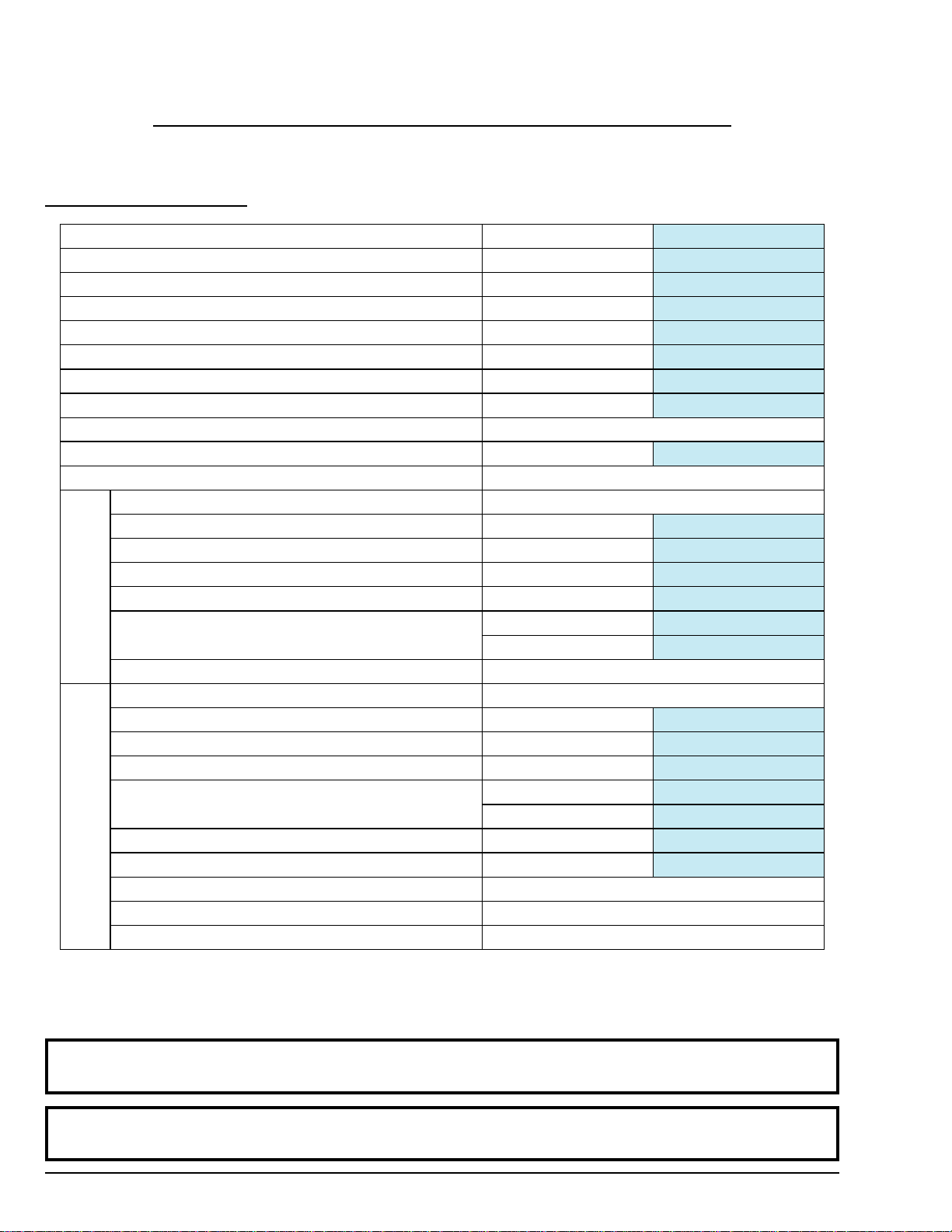
MAXIMUM CAPACITY (DRY WEIGHT) 200 lb 90.9 kg
TUMBLER DIAMETER 62-1/2 158.75 cm
TUMBLER DEPTH 42 106.7 cm
TUMBLER VOLUME 74.5 cu ft 2,109.60 L
TUMBLER / DRIVE MOTOR 3 hp 2.24 kW
DOOR OPENING (DIAMETER) *36-3/4 w x 43 h 93.3 cm x 109.2 cm
DOOR SILL HEIGHT – LEVEL 37-1/4 94.6 cm
COMPRESSED AIR VOLUME 9 cfh 0.25 cmh
COMPRESSED AIR CONNECTION ** 3/8 F.N.P.T.
EXHAUST CONNECTION (DIAMETER) 20 50.8 cm
WATER CONNECTION *** 3/4 F.N.P.T.
VOLTAGE AVAILABLE 208-575V 3ø 3,4w 50/60 Hz
BLOWER / FAN MOTOR (REAR / SIDE EXHAUST) 7-1/2 hp / 15 hp 5.6 kW / 11.2 kW
APPROXIMATE NET WEIGHT 3,370 lb 1,529 kg
APPROXIMATE SHIPPING WEIGHT 3,670 lb 1,664 kg
HEAT INPUT 650,000 Btu/hr 163,810 kcal/hr
AIRFLOW 60 Hz 5,300 cfm 150.08 cmm
50 Hz 4,417 cfm 125.07 cmm
INLET PIPE CONNECTION 1-1/2 F.N.P.T.
VOLTAGE AVAILABLE 208-575V 3ø 3,4w 50/60 Hz
BLOWER / FAN MOTOR 15 hp 11.2 kW
APPROXIMATE NET WEIGHT 3,625 lb 1,644 kg
APPROXIMATE SHIPPING WEIGHT 3,925 lb 1,780 kg
AIRFLOW 60 Hz 6,500 cfm 184.06 cmm
50 Hz 5,417 cfm 153.38 cmm
STEAM CONSUMPTION 890 lb/hr 404.5 kg/hr
OPERATING STEAM PRESSURE 125 psi max 8.6 bar
BOILER HORSEPOWER (NORMAL LOAD) 27 Bhp
SUPPLY CONNECTION 1-1/2 M.N.P.T.
RETURN CONNECTION 3/4 M.N.P.T.
Shaded areas are stated in metric equivalents 07/16/03
* Dryer must be provided with clean, dry and regulated 80 psi +/- 10 psi (5.51 bar +/- 0.69 bar) air supply.
** Height is 43-inches (109.22 cm) maximum at the center of the door.
*** Water supply must be 40 psi +/- 20 psi (2.75 bar +/- 1.37 bar) for fire suppression system to operate properly.
NOTE: Dryers must be pro ided with a clean, dry, regulated 80 psi +/- 10 psi (5.51 bar +/- 0.65 bar)
air supply (equi alent olume = 9 cfh [0.26 cmh]).
NOTE: The manufacturer reser es the right to make changes in specifications at any time, without notice or
obligation.
SECTION II
SPECIFICATIONS AND TILTING DIMENSIONS
A. SPECIFICATIONS
Gas
St am

113261 -1 7
B. DIMENSIONS AND LOCATION
NOTE: The manufacturer reser es the right to make changes in specifications at any time, without notice or
obligation.

8113261 -1
NOTE: The manufacturer reser es the right to make changes in specifications at any time, without notice or
obligation.

113261 -1 9
NOTE: The manufacturer reser es the right to make changes in specifications at any time, without notice or
obligation.

10 113261 -1
SECTION III
INSTALLATION PROCEDURES
Installation in a proper location should be performed by competent technicians in accordance with local and state
codes. In the absence of these codes, the installation must conform to applicable American National Standards:
National Fuel Gas Code ANSI.Z223.1-LATEST EDITION and/or National Electrical Code ANSI/NFPA NO. 70-
LATEST EDITION, or in Canada, the Canadian Electrical Codes Parts 1 & 2 CSA C22.1-1990 or LATEST EDITION.
A. REASSEMBLY OF DRYER
IMPORTANT: Always keep the tumbler section of the dryer in an upright position when mo ing it.
The dryer may be shipped one of two ways; as a complete unit fully assembled and ready for hookup or with the
tumbler section separated from the base. If the dryer is shipped in two (2) pieces, the tumbler section will ha e to be
lifted onto the base. Use cables through the eyebolts on top of the tumbler section, or use a forklift for the lifting
process.
The tilting dryer is made in many loading and unloading options. Please refer to the reassembly instructions on the
following pages for your particular style of dryer.
If a steam dryer is shipped in two (2) pieces, the steam coil may ha e been remo ed from the top of the tumbler section
and shipped with the base. If this is the case, lift the steam coil onto the top of the tumbler section with the steam pipe
connections facing towards the right side of the dryer and bolt the coil to the top of the dryer with the 1/4” hardware
supplied. There are three (3) panels that co er the front, right side, and rear of the steam coil. Fasten these in position
also. Reconnect the steam and condensate pipe unions to the coil. These pipes run down to the flex hoses in the base.

113261 -1 11
NOTE: The manufacturer reser es the right to make changes in specifications at any time, without notice or
obligation.
1. Reassembly Instructions For Gas Dryer Shipped In Two Pieces
1 DOOR/2-WAY TILT

12 113261 -1
1 DOOR/2-WAY TILT

113261 -1 13
a. Reassembly For 1 Door/2-Way Tilt Gas Dryers
Lift the tumbler section onto the base.
1) 2-way tilt dryers ha e four (4) tilting pistons in the base, one (1) on each corner. On the top of each piston
is a cle is block. Use the four (4) 1/2” x 1-1/8” hex head bolts with lock washers to secure each piston
cle is block to the bottom of the tumbler section. (Refer to View 1 [top] on the pre ious page.)
2) The flexible gas hose union is disconnected when the dryer is shipped in two (2) pieces. The flexible gas
hose is located in the right side of the base. Insert the flexible hose with the union half up through the hole
on the bottom of the tumbler section and retighten the union. The flex hose must not be kinked. (Refer
to View 2 [center] on the pre ious page.)
3) There are two (2) electrical reconnections:
a) A plug and cable is located in the right side of the base. This must be lifted up and reconnected into
the mating socket located at the bottom of the right tumbler section.
b) The dri e motor wires must be lifted up from the base and reconnected into the junction box next to
the tumbler dri e motor in the left side of the tumbler section.
Make sure both reconnected cables ha e enough slack in them to allow the dryer to tilt freely in both
directions.
4) Reattach the tilt guard panels:
a) Use the 1/4-20 x 3/8” hex head bolts with lock washers to bolt the top of the front tilt guard up into the
bottom of the front of the tumbler section.
b) Use 1/4” self-tapping screws to secure the side tilt guards on the top sides of the base.
c) Use 1/4” self-tapping screws to secure the rear tilt guards on the rear of the base.
Reconnect the spring and claw assembly, which connects the rear tilt guard to each side tilt guard.
(Refer to View 3 [bottom] on the pre ious page.) This spring keeps the rear tilt guard close to the
dryers back as the dryer is tilted forward and back.
5) Secure the 20-inch (50.8 cm) diameter exhaust duct transition piece to the dryer’s rectangular exhaust
duct with the 1/4-20 self-tapping screws supplied with the dryer. The exhaust duct exits from the rear of
the base.
6) On dryers equipped with an automatic (piston operated) load door, reconnect the two (2) poly-flo air lines
that run from the base up to the door pistons.

14 113261 -1
2. Reassembly Instructions For Gas Dryer Shipped In Two Pieces
1 DOOR/FORWARD TILT
NOTE: The manufacturer reser es the right to make changes in specifications at any time, without notice or
obligation.

113261 -1 15
1 DOOR/FORWARD TILT

16 113261 -1
a. Reassembly For 1 Door/Forward Tilt Gas Dryers
Lift the tumbler section onto the base.
1) Forward tilt dryers ha e two (2) tilting pistons in the rear of the base. On the top of each piston is a cle is
block. Use the two (2) 1/2” x 1-1/2” hex head bolts with lock washers to secure each piston cle is block
to the bottom of the tumbler section. (Refer to View 1 [top] on the pre ious page.)
a) Reattach the two (2) base tilting hinges in the front of the dryer to the tumbler section using the 1/2”
x 1-1/2” hex head bolts and lock washers supplied. (Refer to View 1a [center] on the pre ious page.)
2) The flexible gas hose union is disconnected when the dryer is shipped in two (2) pieces. The flexible gas
hose is located in the right side of the base. Insert the flexible hose with the union half up through the hole
on the bottom of the tumbler section and retighten the union. The flex hose must not be kinked. (Refer
to View 2 [bottom] on the pre ious page.)
3) There are two (2) electrical connections:
a) A plug and cable is located in the right side of the base. This must be lifted up and reconnected into
the mating socket located at the bottom of the right tumbler section.
b) The tumbler section power cable must be lifted up from the base and reconnected into the junction
box next to the tumbler dri e motor in the left side of the tumbler section.
Make sure both reconnected cables ha e enough slack in them to allow the dryer to tilt freely in both
directions.
4) Reattach the tilt guard panels:
a) Use 1/4” self-tapping screws to secure the right side and left side tilt guards.
b) Use 1/4” self-tapping screws to secure the rear tilt guards on the rear of the base. Also secure both
outside edges of the rear tilt guard to each side guard using sheet metal screws.
5) Secure the 20-inch (50.8 cm) diameter exhaust duct transition piece to the dryer’s rectangular exhaust
duct with the 1/4-20 self-tapping screws supplied with the dryer. The exhaust duct exits from the rear of
the base.
6) On dryers equipped with an automatic (piston operated) load door, reconnect the two (2) poly-flo air lines
that run from the base up to the door pistons.
Table of contents
Other MAXIDRY Dryer manuals
Popular Dryer manuals by other brands

Candy
Candy GVH 9813NA1 Instruction book

Miele
Miele PT 7136 OPERATING AND INSTALLATION Manual

VS Sassoon
VS Sassoon VSLE5223A Instruction booklet

LG
LG DLE3777 owner's manual

SPL
SPL SUPREME AIRFORCE Installation & maintenance instructions

American Dryer Corp.
American Dryer Corp. AD-100 Installation/service parts