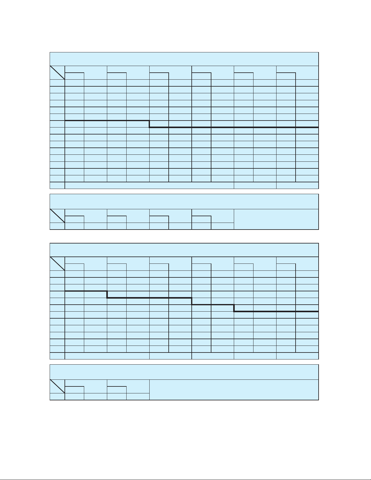
R W R W R W R W R W R W R W R W
82
o
12.6 3,300 16.7 2,650 19.6 2,000 21.5 1,400 82
o
13.9 1,850 20.0 1,550 24.7 1,300 27.2 850
80
o
16.1 3,300 20.0 2,650 22.7 2,000 24.6 1,400 80
o
17.5 1,850 23.5 1,550 28.0 1,300 30.1 850
77.5
o
20.4 3,300 24.2 2,650 26.5 2,000 28.1 1,400 77.5
o
21.9 1,850 27.9 1,550 31.9 1,200 33.9 850
75
o
24.4 3,300 28.1 2,650 30.3 2,000 31.9 1,400 75
o
26.3 1,850 32.1 1,550 35.8 1,200 37.4 850
72.5
o
28.3 3,000 31.8 2,400 33.9 1,900 35.3 1,400 72.5
o
30.6 1,850 36.0 1,500 39.6 1,200 41.2 850
70
o
32.1 2,750 35.4 2,200 37.4 1,850 38.9 1,400 70
o
34.7 1,850 39.7 1,400 43.1 1,150 44.5 850
67.5
o
35.7 2,500 38.9 2,100 40.8 1,800 41.9 1,400 67.5
o
38.6 1,800 43.3 1,350 46.5 1,100 47.9 850
65
o
39.2 2,300 42.3 1,950 44.2 1,700 45.3 1,400 65
o
42.5 1,750 47.1 1,300 49.8 1,100 50.9 850
62.5
o
42.8 2,100 45.7 1,850 47.3 1,600 48.1 1,400 62.5
o
46.1 1,600 50.5 1,250 53.0 1,100 54.0 850
60
o
46.1 1,950 49.0 1,750 50.3 1,550 51.1 1,400 60
o
49.6 1,450 53.8 1,200 56.1 1,050 56.8 850
57.5
o
49.1 1,750 51.9 1,600 53.3 1,500 57.5
o
53.1 1,350 57.2 1,150 59.1 1,000
55
o
52.1 1,550 54.9 1,400 56.0 1,400 55
o
56.4 1,250 60.3 1,100 61.9 1,000
52.5
o
55.1 1,300 57.7 1,200 58.6 1,200 52.5
o
59.5 1,100 63.3 1,000 64.7 950
50
o
57.9 1,100 60.3 1,000 61.2 1,050 50
o
62.7 1,000 66.0 900 67.4 900
47.5
o
60.7 950 62.8 900 63.6 900 47.5
o
65.4 850 68.7 800 69.8 800
45
o
63.2 800 65.3 750 65.8 750 45
o
68.1 700 71.2 650 72.0 650
42.5
o
5.240066.760077.56
o
70.8 600 73.7 550
40
o
040059.960551.86
o
73.4 500 76.0 450
37.5
o
70.4 450 72.0 400
35
o
72.5 350 73.9 350
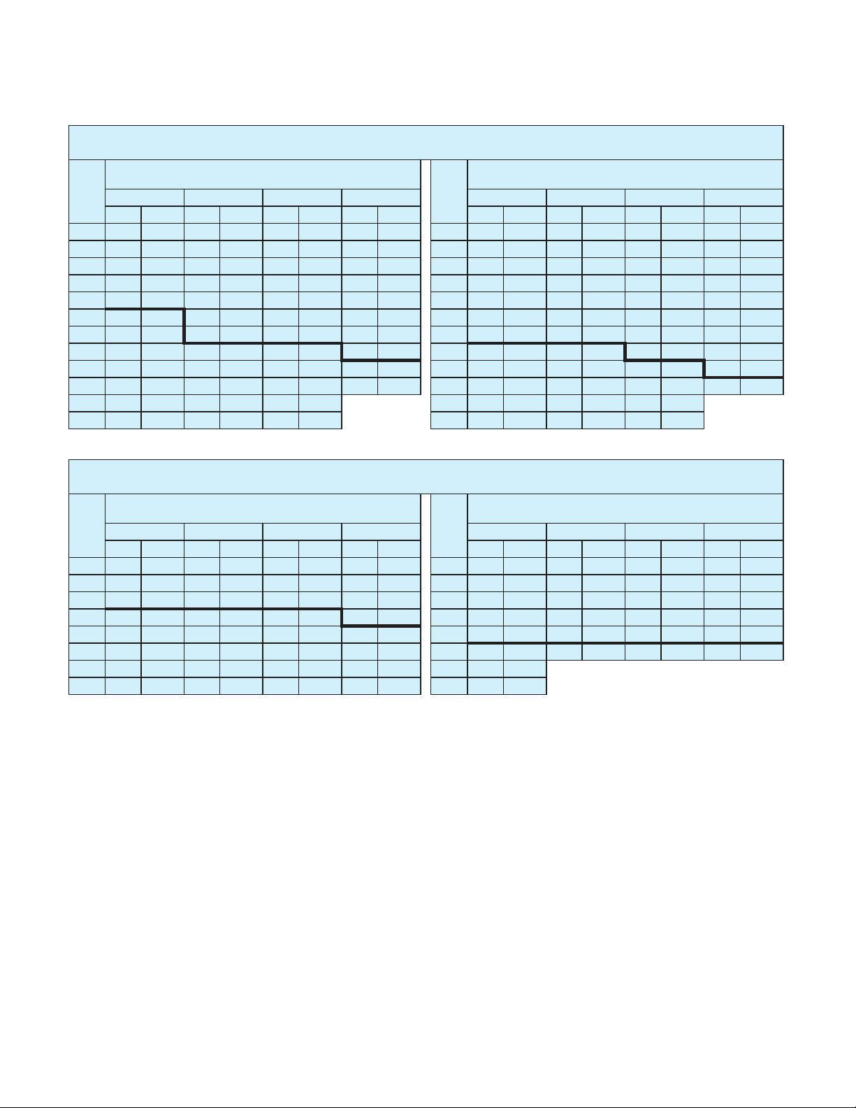
R W R W R W R W R W R W R W R W
82
o
12.6 3,300 16.7 2,650 19.6 2,000 21.5 1,400 82
o
13.9 1,850 20.0 1,550 24.7 1,300 27.2 850
80
o
16.1 3,300 20.0 2,650 22.7 2,000 24.6 1,400 80
o
17.5 1,850 23.5 1,550 28.0 1,300 30.1 850
77.5
o
20.4 3,300 24.2 2,650 26.5 2,000 28.1 1,400 77.5
o
21.9 1,850 27.9 1,550 31.9 1,200 33.9 850
75
o
24.4 3,300 28.1 2,650 30.3 2,000 31.9 1,400 75
o
26.3 1,850 32.1 1,550 35.8 1,200 37.4 850
72.5
o
28.3 3,000 31.8 2,400 33.9 1,900 35.3 1,400 72.5
o
30.6 1,850 36.0 1,500 39.6 1,200 41.2 850
70
o
32.1 2,750 35.4 2,200 37.4 1,850 38.9 1,400 70
o
34.7 1,850 39.7 1,400 43.1 1,150 44.5 850
67.5
o
35.7 2,500 38.9 2,100 40.8 1,800 41.9 1,400 67.5
o
38.6 1,800 43.3 1,350 46.5 1,150 47.9 850
65
o
39.2 2,300 42.3 1,950 44.2 1,700 45.3 1,400 65
o
42.5 1,750 47.1 1,300 49.8 1,100 50.9 850
62.5
o
42.6 2,000 45.7 1,800 47.3 1,550 48.1 1,400 62.5
o
46.1 1,600 50.5 1,250 53.0 1,100 54.0 850
60
o
45.8 1,750 48.9 1,600 50.3 1,400 51.1 1,400 60
o
49.6 1,450 53.8 1,200 56.1 1,050 56.8 850
57.5
o
48.9 1,500 51.8 1,400 53.1 1,250 57.5
o
52.9 1,300 57.2 1,100 59.1 950
55
o
51.9 1,200 54.7 1,150 55.8 1,100 55
o
56.1 1,100 60.2 1,000 61.9 850
52.5
o
54.8 1,000 57.3 950 58.4 900 52.5
o
59.3 900 63.0 850 64.6 800
50
o
57.7 800 60.1 750 61.0 750 50
o
62.3 750 65.9 700 67.2 700
47.5
o
60.4 650 62.6 600 63.4 600 47.5
o
65.2 600 68.6 600 69.7 600
45
o
63.0 500 65.1 500 65.7 500 45
o
68.0 500 71.1 450 71.9 450
C:Loaded boom angle (deg.)
R:Load radius in feet
W:Rated lifting capacity in pounds
60
o
Tilt
60
o
Tilt60
o
Tilt
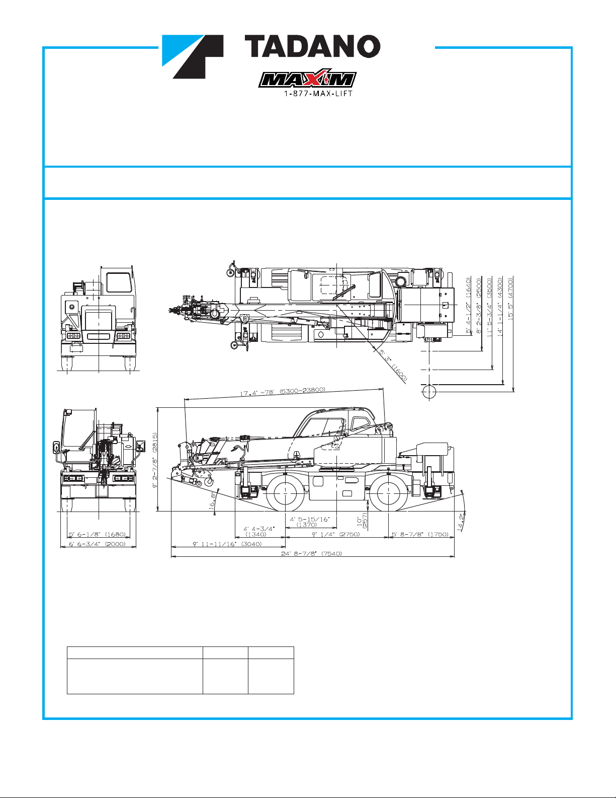
ON OUTRIGGERS FULLY EXTENDED15' 5" (4.7m) SPREAD
5
o
Tilt
5
o
Tilt 25
o
Tilt 45
o
5tliT
o
Tilt
25
o
Tilt
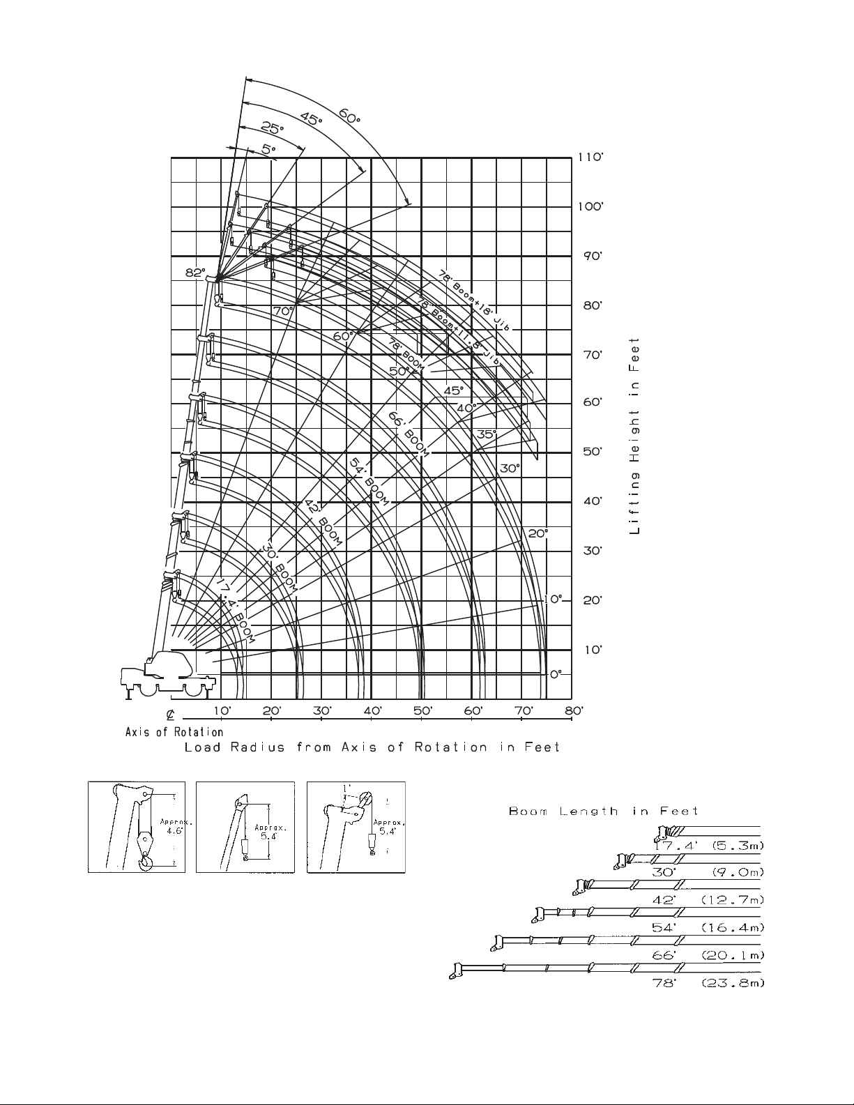
GR-150XL RATED LIFTING CAPACITIES
(IN POUNDS)
45
o
Tilt
C
360
o
ROTATION
C
biJ)m5.5('81+mooB)m8.32('87biJ)m6.3('8.11+mooB)m8.32('87
60
o
52tliT
o
Tilt
45
o
Tilt
ON OUTRIGGERS MID EXTENDED 14' 1-1/4'' (4.3m) SPREAD
360
o
ROTATION
C
78' (23.8m) Boom + 11.8' (3.6m) Jib
C
78' (23.8m) Boom +18' (5.5m) Jib
5
o
Tilt 25
o
Tilt 45
o
Tilt
9