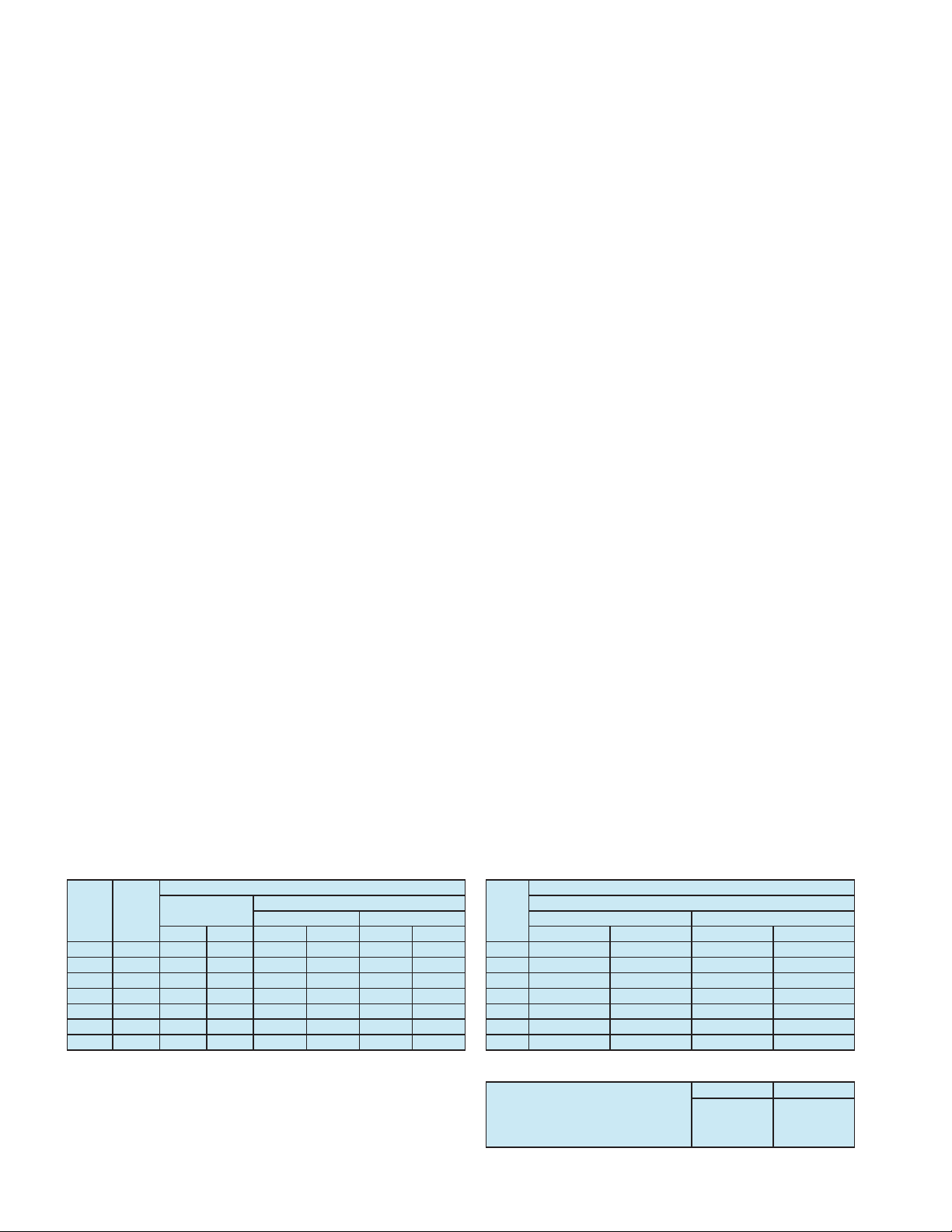
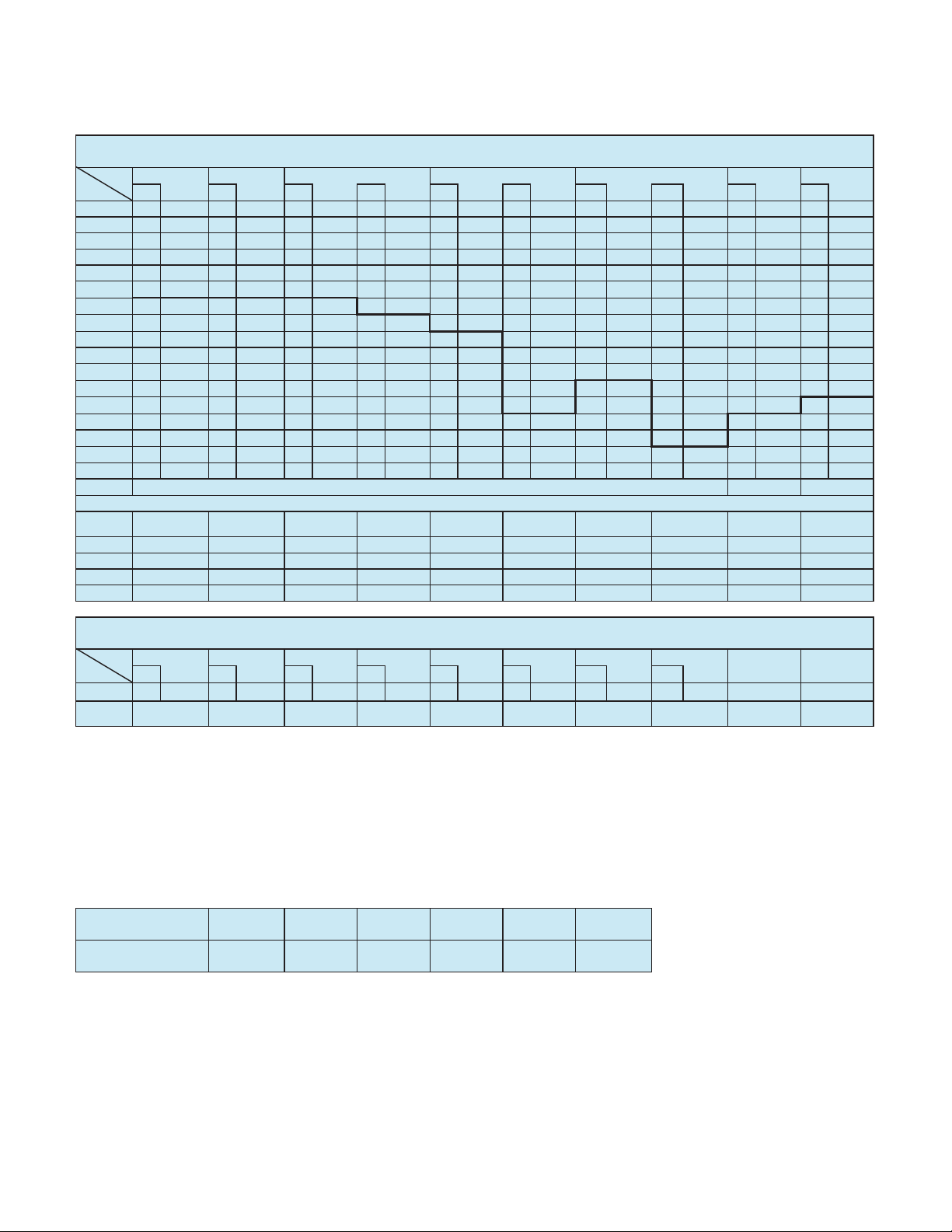
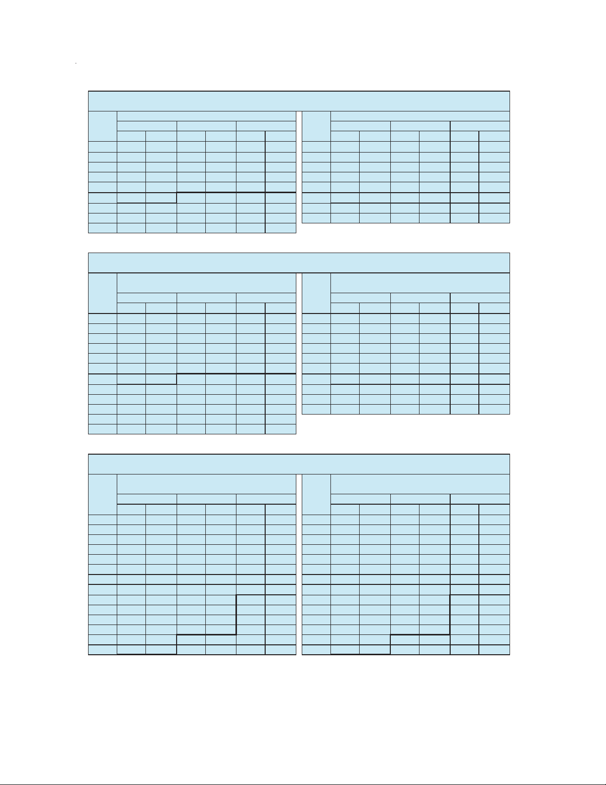
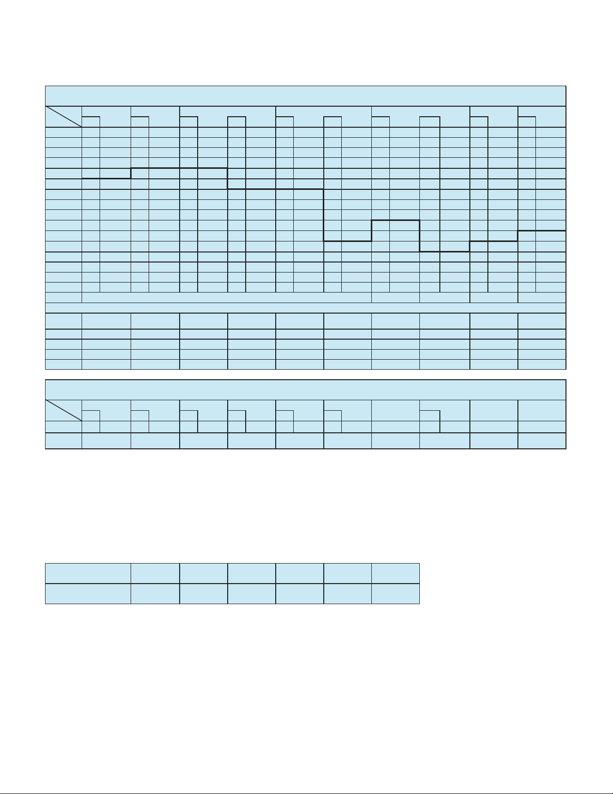
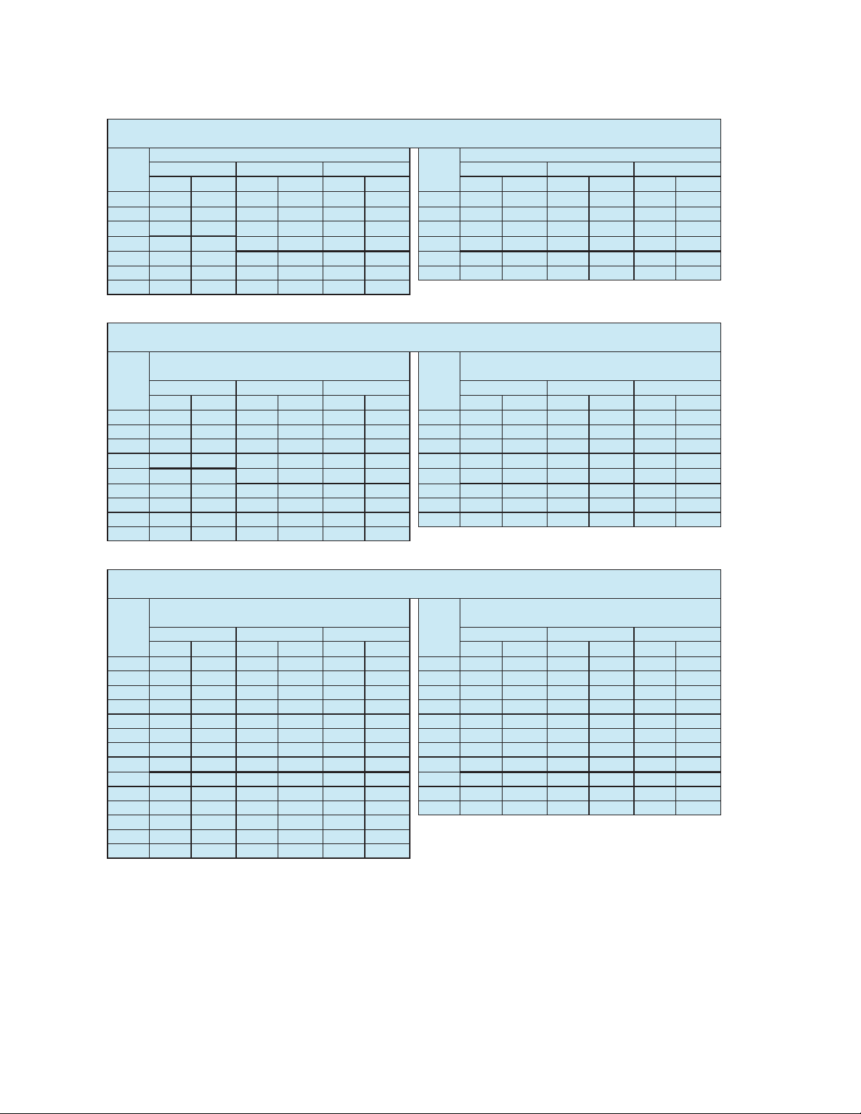
GR-800XL RATED LIFTING CAPACITIES (IN POUNDS)
RWRWRW RWRWRW
80o32.7' 9,900 44.5' 8,800 52.7' 8,100 80o40.6' 5,900 64.3' 5,400 73.5' 3,400
75o50.3' 9,900 61.2' 8,700 67.6' 7,300 75o60.6' 5,900 82.5' 4,800 89.9' 3,400
70o66.4' 9,700 75.9' 7,600 81.2' 6,600 70o79.3' 5,900 98.7' 4,200 105.0' 3,400
65o80.5' 7,900 89.3' 6,600 93.9' 6,000 65o95.6' 4,900 114.0' 3,700 118.0' 3,100
60o93.7' 6,300 102.0' 5,700 106.0' 5,400 60o111.0' 4,100 126.0' 3,300 131.0' 2,900
55o106.0' 5,100 113.0' 4,500 116.0' 4,300 55o124.0' 3,100 141.0' 2,900 142.0' 2,700
50o117.0' 3,500 124.0' 3,100 125.0' 3,000 50o137.0' 2,100 151.0' 1,800 152.0' 1,700
45o127.0' 2,200 133.0' 2,000 134.0' 2,000 45o149.0' 1,200
40o137.0' 1,300 142.0' 1,200
RWRWRW RWRWRW
80o26.1' 12,300 37.7' 11,000 44.8' 8,400 80o33.6' 7,900 55.1' 5,700 67.0' 3,700
75o40.1' 12,300 50.7' 10,000 57.0' 8,000 75o50.4' 7,900 70.3' 5,200 80.7' 3,700
70o53.6' 12,100 62.9' 8,800 68.5' 7,400 70o65.9' 7,100 84.4' 4,700 93.1' 3,600
65o65.7' 9,900 74.6' 7,700 79.0' 6,700 65o80.2' 6,000 97.2' 4,200 104.0' 3,500
60o76.9' 8,400 85.2' 6,800 88.9' 6,200 60o93.5' 5,100 109.0' 3,800 114.0' 3,300
55o87.6' 7,000 95.4' 6,000 98.2' 6,000 55o106.0' 4,500 120.0' 3,500 124.0' 3,100
50o97.5' 5,800 104.0' 5,200 106.0' 5,400 50o117.0' 3,900 130.0' 3,200 132.0' 3,000
45o106.0' 4,300 113.0' 4,000 114.0' 4,200 45o127.0' 2,900 138.0' 2,600 140.0' 2,600
40o115.0' 3,200 120.0' 3,000 40o136.0' 2,000 146.0' 1,800
35o122.0' 2,400 126.0' 2,300 35o145.0' 1,300 153.0' 1,200
30o128.0' 1,700 132.0' 1,700
25o134.0' 1,200 137.0' 1,200
RWRWRW RWRWRW
80o26.8' 11,000 39.1' 10,300 46.6' 8,300 80o34.2 6,300 56.8 5,700 67.7' 3,700
75o41.0' 11,000 52.3' 9,300 58.8' 7,700 75o51.0 6,300 71.7 5,100 81.4' 3,700
70o54.5' 10,600 64.5' 8,000 70.1' 6,900 70o67.0 6,300 85.4 4,400 93.8' 3,600
65o66.3' 8,600 75.9' 7,000 80.4' 6,200 65o80.9 5,300 98.4 3,900 105.0' 3,300
60o77.6' 7,100 86.6' 6,200 90.2' 5,700 60o94.2 4,500 110.0 3,500 115.0' 3,000
55o88.4' 5,900 96.5' 5,300 98.9' 5,200 55o106.0 3,900 121.0 3,100 124.0' 2,800
50o98.2' 5,000 105.0' 4,600 107.0' 4,500 50o118.0 3,300 131.0 2,800 132.0' 2,700
45o107.0' 4,300 113.0' 4,100 114.0' 4,000 45o128.0 2,800 139.0 2,600 140.0' 2,500
40o115.0' 3,800 120.0' 3,600 40o137.0 2,400 147.0 2,300
35o122.0' 3,400 127.0' 3,300 35o145.0 2,100 153.0 2,000
30o129.0' 3,100 132.0' 3,000 30o153.0 1,900 159.0 1,800
25o134.0' 2,800 137.0' 2,800 25o159.0 1,700 163.0 1,700
20o139.0' 2,650 20
164.0 1,550
15
142.0' 2,500 15
168.0 1,450
C:Loaded boom angle (deg.)
R:Load radius in feet
W:Rated lifting capacity in pounds
C
ON OUTRIGGERS FULLY EXTENDED 23' 7-1/2'' (7.2m) SPREAD
360oROTATION
ON OUTRIGGERS FULLY EXTENDED 23' 7-1/2'' (7.2m) SPREAD
360oROTATION
25ooffset 45ooffset
117.7' (35.87m) Boom (telescoping mode II)
+ 32.5' (9.9m) Jib
117.7' (35.87m) Boom (telescoping mode II)
+ 58.1' (17.7m) Jib
3.5ooffset 45ooffset
C
3.5ooffset 25ooffset 45ooffset 3.5ooffset
25ooffset 45ooffset 3.5ooffset 25ooffset
C
ON OUTRIGGERS FULLY EXTENDED 23' 7-1/2'' (7.2m) SPREAD
360oROTATION
C
3.5ooffset 25ooffset 45ooffset
C
117.7' (35.87m) Boom (telescoping mode I)
+ 32.5' (9.9m) Jib
117.7' (35.87m) Boom (telescoping mode I)
+ 58.1' (17.7m) Jib
144.4' (44.0m) Boom + 58.1' (17.7m) Jib144.4' (44.0m) Boom + 32.5' (9.9m) Jib
3.5ooffset 25ooffset 45ooffset C
7