Panasonic Grid-EYE User manual

QUICK START GUIDE
Grid-EYE Evaluation Kit
User Manual
Grid-EYE Evaluation Kit

1
User Manual Grid-EYE Evaluation Kit
Content
1Terms & Abbreviations................................................................................................................. 3
2Introduction....................................................................................................................................4
2.1 Product Introduction......................................................................................................... 4
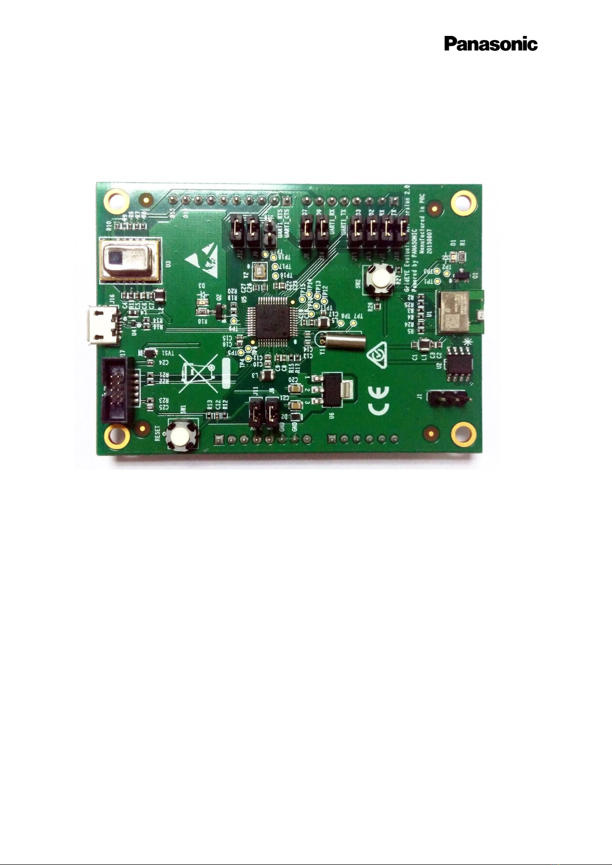
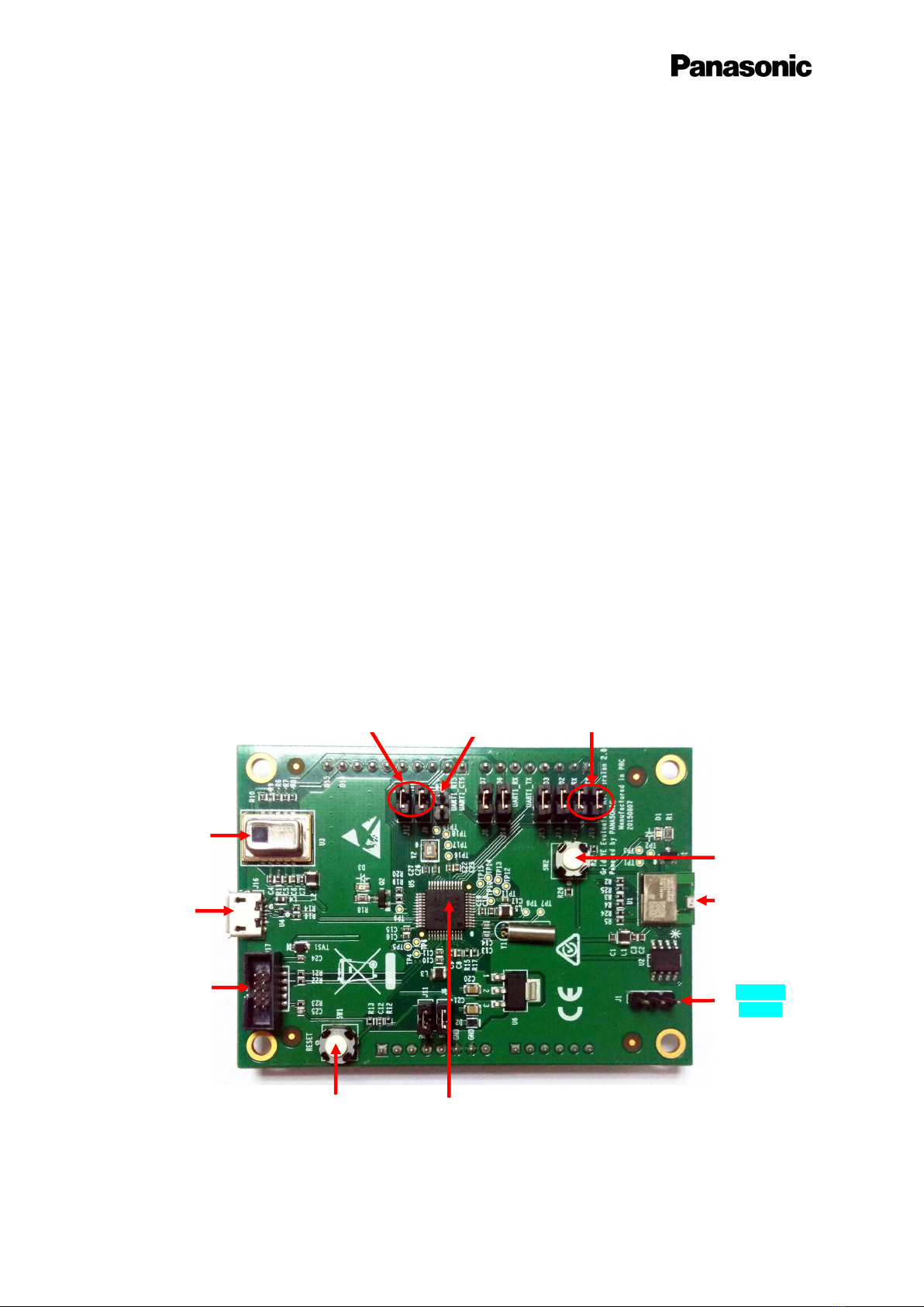
2.2 Evaluation Kit Component Details................................................................................. 5
2.2.1 Grid-EYE Sensor....................................................................................................... 6
2.2.2 ATSAMD21- SMART ARM-Based Microcontroller .................................................. 7
2.2.3 Bluetooth Module PAN1740 ...................................................................................8
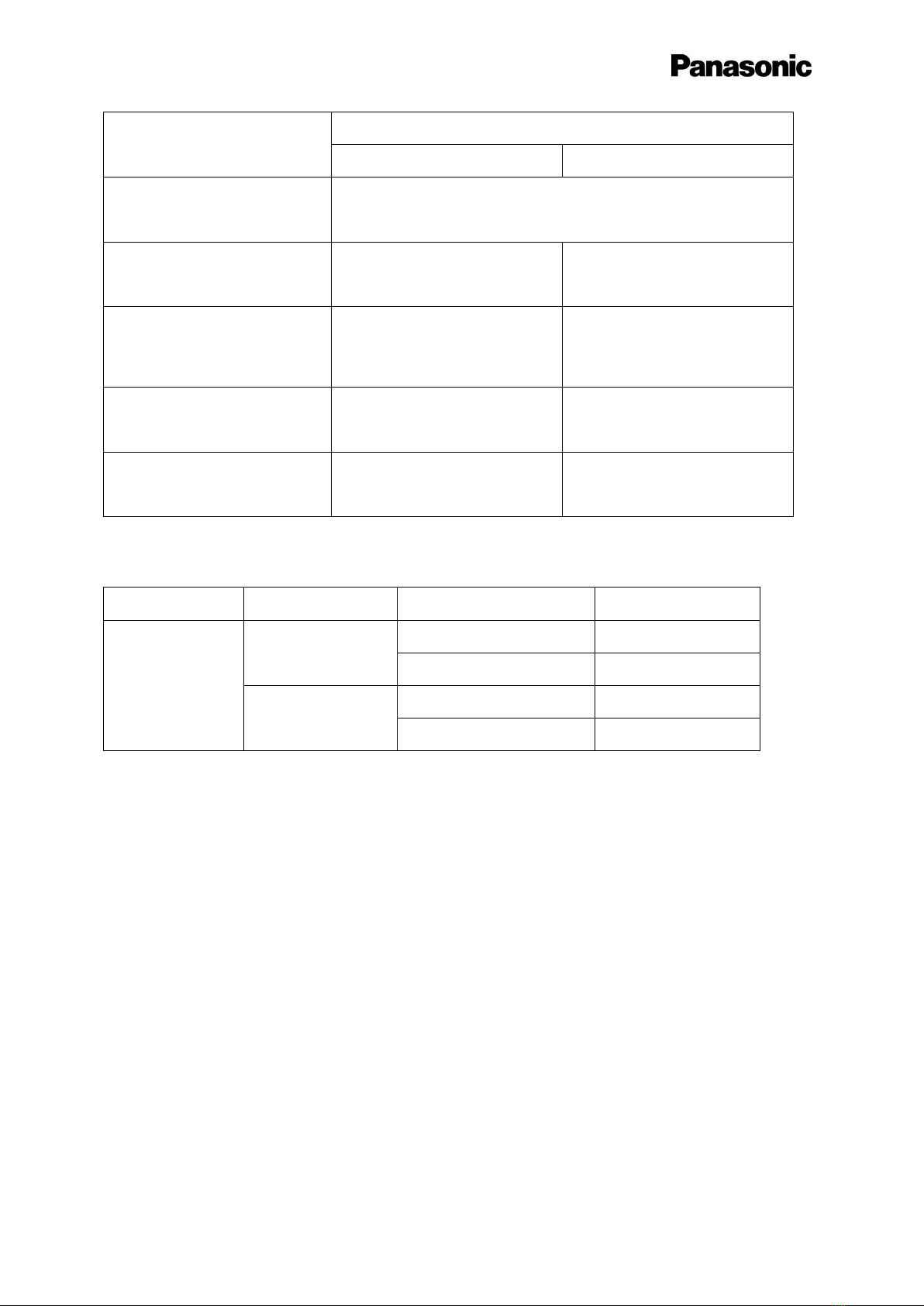
3Interface Definition........................................................................................................................ 9
3.1 Download & Debug..........................................................................................................9
3.1.1 USB interface pin definition (J16) ........................................................................... 9
3.1.2 Serial Wire Debug interface Header definition (J17) ............................................10
3.1.3 Serial Wire Debug port for PAN1740 Header definition (J1) ................................10
3.1.4 Arduino Interfaces (J2, J3, J4 and J5) .................................................................... 11
3.1.5 Arduino Analog I/O A0-A5 pin definitions (J2)......................................................12
3.1.6 Arduino Digital I/O D0-D7 pin definition (J3) ........................................................12
3.1.7 Arduino Power port pin definition (J4) .................................................................13
3.1.8 Arduino Digital I/O D8-D15 pin definition (J5) ......................................................13
3.1.9 Other Jumpers Definition......................................................................................14
4Development with Evaluation Kit.............................................................................................. 15
4.1 Firmware architecture....................................................................................................15
4.1.1 Independent Mode ...............................................................................................15
4.1.2 Arduino Mode .......................................................................................................17
4.2 Firmware development..................................................................................................19
4.2.1 Development Tools ...............................................................................................19
4.2.2 Development on ATSAMD21 ................................................................................20
4.2.3 Development with Grid-EYE APIs..........................................................................21

2
User Manual Grid-EYE Evaluation Kit
4.2.4 Development on Arduino...................................................................................... 22
4.2.5 Development on PAN1740..........................................................................................25
4.3 Updating firmware..........................................................................................................28
4.3.1 Use USB interface to update ATSAMD21G18A.....................................................28
4.3.2 Use Serial interface to update PAN1740...............................................................30
5Grid-EYE Demonstration Software for PC.............................................................................. 35
5.1 Preparation......................................................................................................................35
5.1.1 Jumper Setting ......................................................................................................35
5.2 Demonstration.................................................................................................................36
5.2.1 Independent Mode Demonstration......................................................................36
5.2.2 Arduino Mode Demonstration..............................................................................40
6Appendix...................................................................................................................................... 43
6.1 Install USB Driver for ATSAMD21G18A.....................................................................43
7ESD precautions and proper handling procedures...............................................................46
8Compliance Information.............................................................................................................47

3
User Manual Grid-EYE Evaluation Kit
1 Terms & Abbreviations
The following terms & abbreviations will be referenced in this document:
Term / Abbreviation
Definition
BT
Bluetooth ( refers to PAN1740)
CDC
Communications Device Class
HW
Hardware
I2C / IIC / I2C
Inter-Integrated-Circuit
I/O
Input / Output
IoT
Internet of Things
IR
Infrared
JTAG
Joint Test Action Group
MCU
Microcontroller
PC
Personal Computer
SW
Software
SWD
SerialWire Debug
UART
Universal Asynchronous Receive Transmit
USB
Universal Serial Bus

4
User Manual Grid-EYE Evaluation Kit
2 Introduction
This user manual is aimed at giving the customers an overview of the latest evaluation kit for
Grid-EYE sensor released by Panasonic. The following picture shows how your evaluation
kit should look like when you take it out of the box.
2.1 Product Introduction
Grid-EYE Infrared (IR) Array sensor Evaluation Kit combines the Panasonic’s state of the art
Grid-EYE sensor, Panasonic ”nanopower” PAN1740 Bluetooth Smart module and a
microcontroller on one PCB. By combining its new IR sensor technology with Bluetooth
technology and software for IR detection of people and objects on one board, Panasonic
enables customers to develop rapid prototypes and quickly build their own wireless sensor
“Internet of Things” applications.
To make it simpler and easier for the user, Panasonic has been flexible in the development
of this evaluation kit. The board functions in a standalone mode or it can be connected to an
Arduino host board if the user wants to realize the functionality of the sensor with more than
the provided interfaces. The two operating modes of the evaluation kit are explained below:

5
User Manual Grid-EYE Evaluation Kit
1) Independent mode
The onboard microcontroller ATSAMD21G18 receives the infrared image data sampled by
Grid-EYE sensor through the I2C interface, and then sends this data to a PC and
smartphone via USB and Bluetooth, respectively.
2) Arduino mode
Arduino mother board receives the data sampled by Grid-EYE sensor through the I2C
interface and then sends the data to a PC and smartphone via USB and Bluetooth,
respectively. In this mode the microcontroller, ATSAMD21G18, acts as USB CDC device
and provides a communication channel between Arduino mother board and PC.
In both of the two modes, the Bluetooth module provides a communication channel between
the microcontroller or the Arduino mother board, and smartphone.
2.2 Evaluation Kit Component Details
Grid-EYE
Sensor
JTAG
Bluetooth
SWD I/O
Reset
ATSAMD21G18A
mcu
J7 / J10
selectable for
Arduino-mode
Bluetooth
Reset
PAN1740
Bluetooth
Module
J12 / J9
selectable for
Arduino-mode
J18
Bootloader
access
header
Micro USB
port

6
User Manual Grid-EYE Evaluation Kit
WARNING
The jumper shunt for the pin-header designated J18 must not be placed on the
pin-header prior to using the board, unless the intent is to access the
Bootloader.
The Grid-EYE board has Arduino headers soldered on for convenience, should
the user choose to host the board onto an Arduino (DUE) mother board. Users
are reminded to be careful so not short-out the pins or have the board resting
on a conductive surface.
2.2.1 Grid-EYE Sensor
Specification
Value
Power voltage
3.3V ±10%, 5V ±10%/
Current consumption
4.5mA (normal), 0.8mA (standby), 0.2mA (sleep)
View angle
60 degrees (x,y)
Absolute temperature accuracy
High gain: ±2.5oC (typ.)
Low gain: ±3.0ºC (typ.)
Noise Equivalent Temperature
Difference
0.5°C @ 10Hz
Frame rate (selectable):
1 frame/sec or 10 frames/sec
External interface
I2C(12bit)
Operation mode
Normal, Standby, Sleep (Selectable)
Number of Pixel
64 - (Vertical 8 × Horizontal 8 Matrix)
Grid-EYE Sensor options:
Whilst the Evaluation Kit hosts and demonstrates capabilities of the 3.3V, Low Gain device,
the user has the following options available for design-in and application:
3.3V high gain
3.3V low gain
5V high gain
5V low gain

7
User Manual Grid-EYE Evaluation Kit
Item
Performance
High Gain
Low Gain
Applied Voltage
3.3V +/- 0.3V or 5.0V =/- 0.5V
Detection temperature range
+32°F to 176°F (0°C to +80°C)
-4°F to 212°F (-20°C to +100°C)
Temperature range of measured
object
+32°F to 176°F (0°C to +80°C)
-4°F to 212°F (-20°C to +100°C)
Operating temperature range
+32°F to 176°F (0°C to +80°C)
-4°F to 176°F (-20°C to +80°C)
Storage temperature range
-4°F to 176°F (-20°C to +80°C)
Part Numbers:
Product Name
Operating Voltage
Amplification factor
Part Number
Infrared array sensor
Grid-EYE
3.3V DC
High Gain
AMG8831
Low Gain
AMG8832
5.0V DC
High Gain
AMG8851
Low Gain
AMG8852
The sensors are packaged in a 8mm x 11.6mm x 4.3mm SMD reflow mountable ‘can’
package. The packaging of the sensor is moisture proof, comparable to MSL level 3.
2.2.2 ATSAMD21- SMART ARM-Based Microcontroller
The Atmel®SMART™ SAM D21 is a series of low-power microcontrollers using the 32-bit
ARM® Cortex®-M0+ processor, with identical peripheral modules, hex compatible code,
identical linear address map and pin compatible paths between all devices in the product
series. All devices include intelligent and flexible peripherals, Atmel Event System for inter-
peripheral signaling, and support for capacitive touch button, slider and wheel user
interfaces. The Grid-EYE sensor board hosts the ATSAMD21G18A variant in a 48-pin QFN
package, ideal for a wide range of home automation, consumer, metering, and industrial

8
User Manual Grid-EYE Evaluation Kit
applications and supported by Atmel Studio, the Atmel Software Framework and SAMD21
Xplained kits. Basic specifications of the MCU are shown below:
Item
Description
CPU Core
Cortex-M0+
Max. CPU frequency
48MHz
ROM
256K
RAM
32K
USB
Full-speed USB 2.0 (Support USB Host and USB device)
I2C
Up to 3.4MHz
UART
Up to 3.4MHz
Power Supply
1.62V to 3.63V
More details are available from:
http://www.atmel.com/Images/Atmel-42181-SAM-D21_Datasheet.pdf
2.2.3 Bluetooth Module PAN1740
The PAN1740 is a short-range BLE single mode module compliant with the Bluetooth V4.0
standard. It includes dedicated hardware for the Link Layer implementation of Bluetooth®
Smart and interface controllers for enhanced connectivity capabilities. Due to its high
performance, Panasonic chose to use this for the evaluation kit. Basic specifications of this
BT module can be seen below.
Item
Description
CPU Core
Cortex-M0
CPU frequency
16MHz or 32.768KHz
Power Consumption
Max power consumption: 4.9mA (TX and RX).
Bluetooth
Embedded BLE Stack and GATT Profile, qualified to the Bluetooth 4.0
standard
Operating Temperature
-40°C to 85°C
Gain
93dBm
More details on this BT module can be found on the following link:
https://pideu.panasonic.de/products/wireless-modules/bluetooth/bluetooth-40-low-energy-
single-mode/PAN1740-Bluetooth-Ultra-Low-Energy-Module.html

9
User Manual Grid-EYE Evaluation Kit
3 Interface Definition
This section of the manual will explain about the onboard USB interface, software debug
interface, and pin definitions for J1 - J8.
3.1 Download & Debug
Below you can see the definition of different headers and interfaces on the evaluation kit.
3.1.1 USB interface pin definition (J16)
The Micro USB interface on the evaluation kit is used for power supply and communication
with the external PC. The definition of USB pins is defined below in the table:
Pin Number
Signal
Function
1
VBUS
+5V
2
DM
USB Data-
3
DP
USB Data+
4
ID
USB ID
5
GND
GND
J2 Arduino header
J4 Arduino header
J4 Arduino header
J5 Arduino header
J3 Arduino header
J17 SWD
J16 USB
J1 SWD for
PAN1740

10
User Manual Grid-EYE Evaluation Kit
3.1.2 Serial Wire Debug interface Header definition (J17)
Serial Wire Debug (SWD) is compatible with all ARM processors and any processor using
JTAG for debugging. It provides a debug port for pin limited packages. It replaces the 5-pin
JTAG port with a clock + single bi-directional data pin, SWDIO and SWCLK, providing all the
normal JTAG debug and test functionality.
Standard 10-pin JTAG Debug & Download Interface are shown below in the table:
Pin Number
Signal
Function
1
VDD3.3
+3.3V
2
SWDIO
SW debug data signal for ATSAMD21
3
GND
GND
4
SWCLK
SW debug clock signal for ATSAMD21
5
GND
GND
6
NC
NC
7
GND
GND
8
NC
NC
9
GND
GND
10
RESET
Reset ATSAMD21 MCU
GND = Ground
NC = Not Connected
3.1.3 Serial Wire Debug port for PAN1740 Header definition (J1)
Standard 10-pin JTAG Debug & Download Interface are shown below in the table:
Pin Number
Signal
Function
1
DIO
SW debug data signal for PAN1740
2
P1_4/SWCLK
SW debug clock signal for PAN1740
3
OTP
One time programming selecting pin for PAN1740

11
User Manual Grid-EYE Evaluation Kit
3.1.4 Arduino Interfaces (J2, J3, J4 and J5)
The following schematics define the pins for each header on the evaluation kit.
Schematics:

12
User Manual Grid-EYE Evaluation Kit
3.1.5 Arduino Analog I/O A0-A5 pin definitions (J2)
On the evaluation kit, analog I/O is not supported. The headers are meant for physical
Arduino compatibility only. The table below shows the pin definitions for this header.
Pin Number
Signal
Function
1
NC
NC
2
NC
NC
3
NC
NC
4
NC
NC
5
NC
NC
6
NC
NC
3.1.6 Arduino Digital I/O D0-D7 pin definition (J3)
The following table shows the pin definition of the J3 header.
Pin Number
Signal
Function
1
TX
D0 for Arduino / TX pin for PAN1740 UART
2
RX
D1 for Arduino / RX pin for PAN1740 UART
3
D2
D2 for Arduino
4
D3
D3 for Arduino
5
UART1_TX
D4 for Arduino / TX pin for ATSAMD21 UART1
6
UART1_RX
D5 for Arduino / RX pin for ATSAMD21 UART1
7
D6
D6 for Arduino
8
D7
D7 for Arduino

13
User Manual Grid-EYE Evaluation Kit
3.1.7 Arduino Power port pin definition (J4)
The following table shows the pin definition of the J4 header.
Pin Number
Signal
Function
1
NC
NC
2
NC
NC
3
NC
NC
4
3.3V
3.3V voltage input power
5
5V
5V voltage input power
6
GND
GND
7
GND
GND
8
NC
NC
3.1.8 Arduino Digital I/O D8-D15 pin definition (J5)
The following table shows the pin definition of the J5 header.
Pin Number
Signal
Function
1
UART1_CTS
D8 for Arduino
2
UART1_RTS
D9 for Arduino
3
NC
D10 for Arduino
4
NC
D11 for Arduino
5
NC
D12 for Arduino
6
NC
D13 for Arduino
7
GND
GND
8
NC
AREF for Arduino
9
D14
D14 for Arduino / SDA pin for
ATSAMD21 I2C
10
D15
D15 for Arduino / SCL pin for
ATSAMD21 I2C

14
User Manual Grid-EYE Evaluation Kit
3.1.9 Other Jumpers Definition
The following table explains several other headers on the evaluation kit.
Connecter
Pin 1
Pin 2
Function
J7
TX
UART_RX
Select to connect RX pin for ATSAMD21 USART1 with D1 for
Arduino and TX for PAN1740 UART.
J10
RX
UART_TX
Select to connect RX pin for PAN1740 UART with TX pin for
ATSAMD21 UART
J13
D2
UART_CTS
Select to connect D2 for Arduino with CTS pin(hardware flow control)
for ATSAMD21 UART
J15
D3
UART_RTS
Select to connect D3 for Arduino with RTS pin(hardware flow control)
for ATSAMD21 UART
J9
D14
SCL
Select to connect SCL pin for ATSAMD21 I2C with SCL pin for Grid-
EYE sensor.
J12
D15
SDA
Select to connect SDA pin for ATSAMD21 I2C with SDA pin for Grid-
EYE sensor.
J8
D7
INT
Select to connect Arduino data pin D7 with Grid-EYE’s interrupt
signal INT.
J6
5V
D2 negative
pole
Select 5V power from Arduino board.
J11
3.3V
VDD3.3
Select 3.3V power from Arduino board.
J14
D6
RESET
Select to connect D6 for Arduino with Reset pin for PAN1740
J18
GND
PA15
Select to connect PA15 for ATSAMD21 to ground.
Jumper settings:
1. J7 and J10 are used to isolate the UART port for the ATSAMD21 microcontroller
when programming the Bluetooth module PAN1740, or engage the board into
Arduino mode.
2. J9 and J12 are used to set up the evaluation kit into either independent mode or
Arduino mode. When J9 and J12 are in-situ, the sensor and ATSAMD21 are
connected via I2C and the board works in independent mode. Removing the two
jumpers will enable the Arduino mode when the Grid-EYE board is hosted onto the
Arduino board. If not hosted onto the Arduino board and jumpers are removed
unexpected and undefined data will be received and/or transmitted.
3. When programming ATSAMD21 with SAM-BA, J18 is placed in-situ to update the
bootloader or start the application. By having the jumper J18 connected and the
reset button SW1 pressed, ATSAMD21 will be ready for updating the bootloader.

15
User Manual Grid-EYE Evaluation Kit
4 Development with Evaluation Kit
For a customized firmware development on the evaluation kit, it is important for the
developer to know the Firmware architecture of the kit in two different modes. This section
explains this in detail.
4.1 Firmware architecture
As explained earlier, there are two modes that the board can be used in. Independent mode,
and Arduino mode.
4.1.1 Independent Mode
The following block diagram illustrates the independent mode of operation for the evaluation
kit, utilizing the standard communications protocols:
Grid-EYE sensor
Smart PhonePAN1740
ATSAMD21G18A
PC
US
B
I2
U
A
R
T
BTL
ARDUINO DUE
UAR
T

16
User Manual Grid-EYE Evaluation Kit
In the independent mode, data sampling and transfer will be executed by the ATSAMD21
microcontroller ; the program flow diagram is given below:
Flow-chart steps explained:
Decision point - check I2C response of Grid-EYE sensor:
oIf valid, Independent mode is confirmed.
oIf invalid, Arduino mode is confirmed.
-Delay of 100ms is applied for periodic inspection of I2C. This allows the
microcontroller to determine mode of operation.
Parse the command from PC, such as the command of setting the sampling frequency.
Measurement - read data from the sensor and send it to PC and smartphone.
Updating frequency - if the sampling frequency is updated, then reset it.
Delay applied in the loop, determined by the sampling frequency.

17
User Manual Grid-EYE Evaluation Kit
4.1.2 Arduino Mode
The following block diagram illustrates Arduino mode of operation for the evaluation kit with
standard communication protocols:
Grid-EYE sensor
SmartphonePAN1740
ATSAMD21G18A
(on Eval board)
PC
USB
I2C
U
A
R
T
BTLE
ARDUINO DUE
UART

18
User Manual Grid-EYE Evaluation Kit
In the Arduino mode, data sampling and transfer will be executed by Arduino mother board;
the program flow diagram is shown below:
Flow-chart steps explained:
Parse the command from PC, such as the command of setting the sampling frequency.
Measurement - Read data from the sensor and send it to PC and smartphone.
If the sampling frequency is updated, then reset the sampling frequency.
Delay applied in the loop, determined by the sampling frequency.

19
User Manual Grid-EYE Evaluation Kit
4.2 Firmware development
For the two modes of operation, independent and Arduino mode, we will explain separately
the development process. We will also give a brief introduction in this section on the
programming of the Bluetooth module built on the evaluation kit.
4.2.1 Development Tools
The following tools are needed when developing application for Grid-EYE Sensor board.
Hardware
1. PC with at least 2 USB interface
2. Micro-USB cables
3. TTL Serial to USB module (only to program Bluetooth module PAN 1740)
4. J-Link
Software
Users need to install the following software according to the target they develop:
Software
Description
Download link
Atmel Studio
Develop the code for
ATSAMD21
http://www.atmel.com/tools/ATMELSTUDIO.aspx
SAM-BA
Program ATSAMD21, if JTAG
is not available
http://www.atmel.com/tools/ATMELSAM-BAIN-
SYSTEMPROGRAMMER.aspx
Arduino IDE
Develop the code for Arduino
mother board
https://www.arduino.cc/en/Main/Software
Keil MDK
Develop the code for
Bluetooth module
http://www.keil.com/arm/mdk.asp
Smart Snippet
Program Bluetooth module
http://support.dialog-
semiconductor.com/product/da14580
Other manuals for Grid-EYE
1
Table of contents
Other Panasonic Motherboard manuals

Panasonic
Panasonic Grid-EYE User manual

Panasonic
Panasonic PAN9320ETU User manual

Panasonic
Panasonic EvalBoard PAN4555 User manual

Panasonic
Panasonic PGA26E07BA-SWEVB008 User manual

Panasonic
Panasonic PAN9520 User manual

Panasonic
Panasonic PAN9420 User manual

Panasonic
Panasonic PGA26E07BA-SWEVB006 User manual

Panasonic
Panasonic AN33014UA User manual

Panasonic
Panasonic PAN4570 User manual

Panasonic
Panasonic EVB-NN30312A User manual