Maximum 5111 User manual


3
NOTE: If any parts are missing or damaged, or if you have any
questions, please call our toll-free helpline at 1-888-670-6682.
SAVE THESE INSTRUCTIONS
This manual contains important safety and
operating instructions. Read all instructions and
follow them with use of this product.
TECHNICAL SPECIFICATIONS 4
SAFETY INSTRUCTIONS 5
IMPORTANT INFORMATION 13
SYMBOL 14
PARTS LIST 15
KNOW YOUR TOOL 17
OPERATING INSTRUCTIONS 19
MAINTENANCE 30
WARRANTY 32
TABLE OF CONTENTS
TABLE OF CONTENTS

4 5
model no. 054-8355-0 | contact us 1-888-670-6682
SAFETY INSTRUCTIONS
TECHNICAL SPECIFICATIONS
MOTOR 18V DC
NO-LOAD SPEED 5000 RPM
SAW BLADE SIZE 6 1/2" (16
.
5 cm)
DEPTH OF CUT AT 90° 2 1/4" (5
.
6 cm)
DEPTH OF CUT AT 45° 1 19/32" (4
.
1 cm)
COMPATIBLE MAXIMUM®BATTERY
054-3203-2 (2.0 Ah) (SOLD SEPARATELY)
;
054-3206-6 (4.0 Ah) (SOLD SEPARATELY)
OPTIMUM CHARGING
TEMPERATURE
40 to 104°F (4–40°C)
COMPATIBLE MAXIMUM®CHARGER 7109-B-2; 054-3204-0 (SOLD
SEPARATELY)
NET WEIGHT 5 lb 10 oz (2.55 kg)
TECHNICAL SPECIFICATIONS GENERAL POWER TOOL SAFETY WARNINGS
Save all warnings and instructions for future reference.
The term “power tool” in the warnings refers to your mains-operated (corded) power
tool or battery operated (cordless) power tool.
WORK AREA SAFETY
• Keep work area clean and well lit. Cluttered or dark areas invite accidents.
• Do not operate power tools in explosive atmospheres, such as in the presence
of flammable liquids, gases or dust. Power tools create sparks which may ignite
the dust or fumes.
• Keep children and bystanders away while operating a power tool. Distractions
can cause you to lose control.
ELECTRICAL SAFETY
• Power tool plugs must match the outlet. Never modify the plug in any way. Do
not use any adaptor plugs with earthed (grounded) power tools. Unmodified
plugs and matching outlets will reduce risk of electric shock.
• Avoid body contact with earthed or grounded surfaces, such as pipes, radiators,
ranges and refrigerators. There is an increased risk of electric shock if your body is
earthed or grounded.
• Do not expose power tools to rain or wet conditions. Water entering a power tool
will increase the risk of electric shock.
• Do not abuse the cord. Never use the cord for carrying, pulling or unplugging
the power tool. Keep cord away from heat, oil, sharp edges or moving parts.
Damaged or entangled cords increase the risk of electric shock.
• When operating a power tool outdoors, use an extension cord suitable for
outdoor use. Use of a cord suitable for outdoor use reduces the risk of electric
shock.
• If operating a power tool in a damp location is unavoidable, use a Residual
Current Device (RCD) protected supply. Use of an RCD reduces the risk of electric
shock.
WARNING!
Read all safety warnings, instructions, illustrations and
specifications provided with this power tool. Failure to follow all
instructions listed below may result in electric shock, fire and/or
serious injury.

6 7
PERSONAL SAFETY
• Stay alert, watch what you are doing and use common sense when operating a
power tool. Do not use a power tool while you are tired or under the influence
of drugs, alcohol or medication. A moment of inattention while operating power
tools may result in serious personal injury.
• Use personal protective equipment. Always wear eye protection. Protective
equipment such as dust mask, non-skid safety shoes, hard hat, or hearing protection
used for appropriate conditions will reduce personal injuries.
• Prevent unintentional starting. Ensure the switch is in the off-position before
connecting to power source and/or battery pack, picking up or carrying the
tool. Carrying power tools with your finger on the switch or energising power tools
that have the switch on invites accidents.
• Remove any adjusting key or wrench before turning the power tool on. A
wrench or a key left attached to a rotating part of the power tool may result in
personal injury.
• Do not overreach. Keep proper footing and balance at all times. This enables
better control of the power tool in unexpected situations.
• Dress properly. Do not wear loose clothing or jewellery. Keep your hair,
clothing and gloves away from moving parts. Loose clothes, jewellery or long
hair can be caught in moving parts.
• If devices are provided for the connection of dust extraction and collection
facilities, ensure these are connected and properly used. Use of dust collection
can reduce dust-related hazards.
• Do not let familiarity gained from frequent use of tools allow you to become
complacent and ignore tool safety principles. A careless action can cause severe
injury within a fraction of a second.
POWER TOOL USE AND CARE
• Do not force the power tool. Use the correct power tool for your application.
The correct power tool will do the job better and safer at the rate for which it was
designed.
• Do not use the power tool if the switch does not turn it on and off. Any power
tool that cannot be controlled with the switch is dangerous and must be repaired.
• Disconnect the plug from the power source and/or remove the battery pack,
if detachable, from the power tool before making any adjustments, changing
accessories, or storing power tools. Such preventive safety measures reduce the
risk of starting the power tool accidentally.
• Store idle power tools out of the reach of children and do not allow persons
unfamiliar with the power tool or these instructions to operate the power tool.
Power tools are dangerous in the hands of untrained users.
• Maintain power tools and accessories. Check for misalignment or binding of
moving parts, breakage of parts and any other condition that may affect the
power tool’s operation. If damaged, have the power tool repaired before use.
Many accidents are caused by poorly maintained power tools.
• Keep cutting tools sharp and clean. Properly maintained cutting tools with sharp
cutting edges are less likely to bind and are easier to control.
• Use the power tool, accessories and tool bits etc., in accordance with these
instructions, taking into account the working conditions and the work to be
performed. Use of the power tool for operations different from those intended
could result in a hazardous situation.
• Keep handles and grasping surfaces dry, clean and free from oil and grease.
Slippery handles and grasping surfaces do not allow for safe handling and control of
the tool in unexpected situations.
BATTERY TOOL USE AND CARE
• Recharge only with the charger specified by the manufacturer. A charger that
is suitable for one type of battery pack may create a risk of fire when used with
another battery pack.
• Use power tools only with specifically designated battery packs. Use of any
other battery packs may create a risk of injury and fire.
• When battery pack is not in use, keep it away from other metal objects, like
paper clips, coins, keys, nails, screws or other small metal objects, that can
make a connection from one terminal to another. Shorting the battery terminals
together may cause burns or a fire.
• Under abusive conditions, liquid may be ejected from the battery; avoid
contact. If contact accidentally occurs, flush with water. If liquid contacts
eyes, additionally seek medical help. Liquid ejected from the battery may cause
irritation or burns.
• Do not use a battery pack or tool that is damaged or modified. Damaged or
modified batteries may exhibit unpredictable behaviour resulting in fire, explosion
or risk of injury.
• Do not expose a battery pack or tool to fire or excessive temperature. Exposure
to fire or temperature above 130 °C (266°F) may cause explosion.
• Follow all charging instructions and do not charge the battery pack or
SAFETY INSTRUCTIONS
SAFETY INSTRUCTIONS
model no. 054-8355-0 | contact us 1-888-670-6682

8 9
• When the blade is pinched or jammed tightly by the kerf closing down, the blade
stalls and the motor reaction drives the unit rapidly back toward the operator.
• If the blade becomes twisted or misaligned in the cut, the teeth at the back edge of
the blade can dig into the top surface of the wood causing the blade to climb out of
the kerf and jump back toward operator.
Kickback is the result of saw misuse and/or incorrect operating procedures or conditions
and can be avoided by taking proper precautions as given below:
• Maintain a firm grip with both hands on the saw and position your arms to
resist kickback forces. Position your body to either side of the blade, but not in
line with the blade. Kickback could cause the saw to jump backwards, but kickback
forces can be controlled by the operator, if proper precautions are taken.
• When blade is binding, or when interrupting a cut for any reason, release the
trigger and hold the saw motionless in the material until the blade comes to a
complete stop. Never attempt to remove the saw from the work or pull the saw
backward while the blade is in motion or kickback may occur. Investigate and
take corrective actions to eliminate the cause of blade binding.
• When restarting a saw in the workpiece, centre the saw blade in the kerf and
check that saw teeth are not engaged in the material. If saw blade is binding, it
may walk up or kick back from the workpiece as the saw is restarted.
• Support large panels to minimise the risk of blade pinching and kickback. Large
panels tend to sag under their own weight. Supports must be placed under the
panel on both sides, near the line of the cut and near the edge of the panel.
• Do not use dull or damaged blade. Unsharpened or improperly set blades produce
narrow kerf causing excessive friction, blade binding and kickback.
• Blade depth and bevel adjusting locking levers must be tight and secure before
making cut. If blade adjustment shifts while cutting, it may cause binding and
kickback.
• Use extra caution sawing into existing walls or other blind areas. The protruding
blade may cut objects that can cause kickback.
tool outside the temperature range specified in the instructions. Charging
improperly or at temperatures outside the specified range may damage the battery
and increase the risk of fire.
SERVICE
• Have your power tool serviced by a qualified repair person using only identical
replacement parts. This will ensure that the safety of the power tool is maintained.
• Never service damaged battery packs. Service of battery packs should only be
performed by the manufacturer or authorized service providers.
SAFETY INSTRUCTIONS FOR ALL SAWS
• Do not reach underneath the workpiece. The guard cannot protect you from the
blade below the workpiece.
• Adjust the cutting depth to the thickness of the workpiece. Less than a full
tooth of the blade teeth should be visible below the workpiece.
• Never hold the workpiece in your hands or across your leg while cutting.
Secure the workpiece to a stable platform. It is important to support the work
properly to minimize body exposure, blade binding, or loss of control.
• Hold power tool by insulated gripping surfaces when performing an operation
where the cutting tool may contact hidden wires. Contact with a “live” wire will
also make exposed metal parts of the power tool “live” and could give the operator
an electric shock.
• When ripping, always use a rip fence or straight edge guide. This improves the
accuracy of cut and reduces the chance of blade binding.
• Always use blades with correct size and shape (diamond versus round) of
arbor holes. Blades that do not match the mounting hardware of the saw will run
off-centre, causing loss of control.
• Never use damaged or incorrect blade washers or bolts. The blade washers and
bolts were specially designed for your saw, for optimum performance and safety of
operation.
FURTHER SAFETY INSTRUCTIONS FOR ALL SAWS
Kickback causes and related warnings
• Kickback is a sudden reaction to a pinched, jammed or misaligned saw blade,
causing an uncontrolled saw to lift up and out of the workpiece toward the
operator.
SAFETY INSTRUCTIONS
SAFETY INSTRUCTIONS
WARNING!
Do not use abrasive wheels or blades.
WARNING!
Do not use water feed attachments.
CAUTION!
Do not attempt to cut stainless steel, rebar, hardened or
heat-treated steel, cast iron, masonry or unknown materials.
model no. 054-8355-0 | contact us 1-888-670-6682
DANGER!
Keep hands away from cutting area and blade. Keep your
second hand on auxiliary handle or motor housing. If both
hands are holding the saw, they cannot be cut by the blade.

10 11
Lower guard function
• Check the lower guard for proper closing before each use. Do not operate saw
if lower guard does not move freely and close instantly. Never clamp or tie the
lower guard into the open position. If the saw is accidentally dropped, the lower
guard may be bent. Raise the lower guard with the lower guard lever and make sure
it moves freely and does not touch the blade or any other part, in all angles and
depths of cut.
• Check the operation of the lower guard spring. If the guard and the spring are
not operating properly, they must be serviced before use. Lower guard may
operate sluggishly due to damaged parts, gummy deposits, or a buildup of debris.
• The lower guard may be retracted manually only for special cuts such as
“plunge cuts” and “compound cuts”. Raise the lower guard by lower guard
lever, and as soon as blade enters the material the lower guard must be
released. For all other sawing, the lower guard should operate automatically.
• Always observe that the lower guard is covering the blade before placing saw
down on bench or floor. An unprotected, coasting blade will cause the saw to
walk backwards, cutting whatever is in its path. Be aware of the time it takes for the
blade to stop after switch is released.
ADDITIONAL SPECIFIC SAFETY INSTRUCTIONS FOR CIRCULAR SAWS
• Use clamps or another practical way to secure and support the workpiece to a
stable platform. Holding the work by hand or against your body leaves it unstable
and may lead to loss of control.
• Keep your body positioned to either side of the blade, but not in line with
the saw blade. Kickback could cause the saw to jump backwards (see Causes and
Operator Prevention of Kickback and Kickback).
• Air vents often cover moving parts and should be avoided. Loose clothes,
jewellery or long hair can be caught in moving parts.
• Avoid cutting nails. Inspect for and remove all nails from lumber before cutting.
• Avoid prolonged contact with dust from power sanding, sawing, grinding,
drilling, and other construction activities.
• Wear protective clothing and wash exposed areas with soap and water.
Allowing dust to get into your mouth, eyes, or lay on the skin may promote
absorption of harmful chemicals.
SAFETY RULES FOR BATTERY PACK AND CHARGER
• If the battery pack casing is cracked or damaged, do not insert into charger. There is
a danger of electric shock or electrocution.
• Don’t allow any liquid to get inside charger. Electric shock may result. To facilitate
cooling of the battery pack after use, avoid placing the charger or battery pack in a
warm environment such as in a metal shed, or a trailer that is not insulated.
• This charger is not intended for any uses other than charging rechargeable batteries.
Any other use may result in risk of fire, electric shock or electrocution.
• Do not place any object on top of the charger or place the charger on a soft surface.
This may result in excessive internal heat. Do not place the charger near any heat
source.
• To reduce the potential risk of damage to the electric plug and cord, pull by the plug
rather than the cord when disconnecting the charger from the power supply.
• Make sure the cord is located so it will not be stepped on, tripped over, or otherwise
subjected to damage or stress.
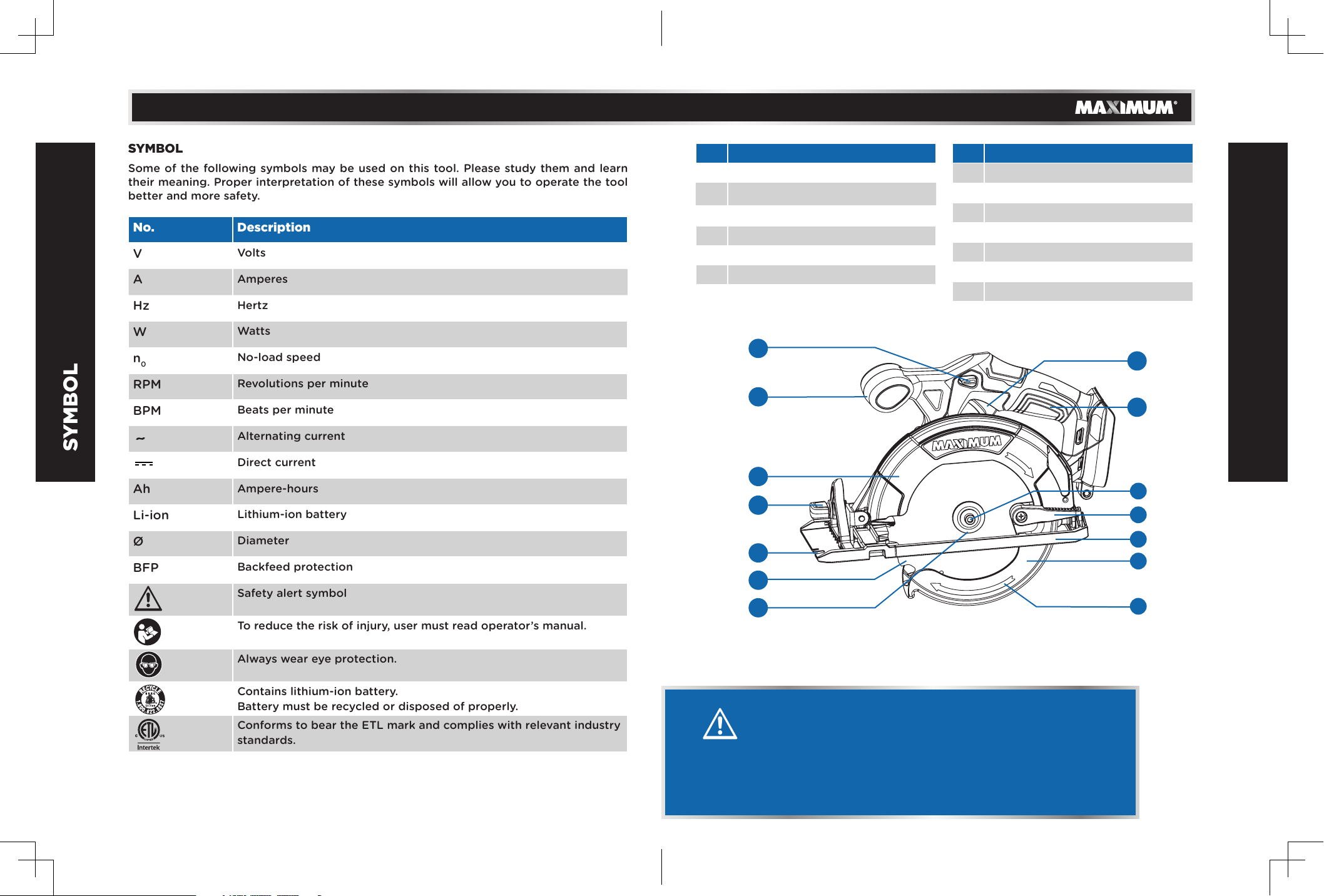
SAFETY INSTRUCTIONS
WARNING: ALWAYS use safety glasses. Everyday eyeglasses are
NOT safety glasses. Also use face or dust mask if cutting operation is
dusty. ALWAYS WEAR CERTIFIED SAFETY EQUIPMENT:
• ANSI Z87.1 eye protection (CAN/CSA Z94.3),
• ANSI S12.6 (S3.19) hearing protection,
• NIOSH/OSHA/MSHA respiratory protection.
WARNING!
Use of this tool can generate and/or disperse dust, which
may cause serious and permanent respiratory or other
injury. Always use NIOSH/OSHA approved respiratory
protection appropriate for the dust exposure. Direct
particles away from face and body. Always operate tool in
well-ventilated area and provide for proper dust removal.
Use dust collection system wherever possible.
WARNING!
Always wear proper personal hearing protection that
conforms to ANSI S12.6 (S3.19) during use. Under some
conditions and duration of use, noise from this product may
contribute to hearing loss.
CAUTION!
When not in use, place circular saw on a stable surface,
shoe side down, where it will not cause a tripping or
falling hazard. Some tools with large battery packs will
stand upright on the battery pack but may be easily
knocked over.
SAFETY INSTRUCTIONS
model no. 054-8355-0 | contact us 1-888-670-6682

1312
• An extension cord should not be used unless absolutely necessary. Use of an
improper extension cord could result in a risk of fire, electric shock or electrocution.
• Do not operate the charger if it has received a sharp blow, been dropped or
otherwise damaged in any way.
• Do not disassemble charger. Take it to a service agent when service or repair is
required. Incorrect reassembly may result in a risk of electric shock, electrocution or
fire.
• To prevent the risk of electric shock, unplug the charger from the outlet before
attempting to clean it. Only removing the battery pack from the charger will not
reduce this risk.
• DO NOT store or use the tool and battery pack in locations where the temperature
may reach or exceed 50°C (122°F), which can lead to deterioration of the storage
battery.
•
The charger is designed to operate on standard household electrical power (120 V~).
Do not attempt to use it on any other voltage.
IMPORTANT INFORMATION
model no. 054-8355-0 | contact us 1-888-670-6682
WARNING!
Upon removal, cover the battery pack’s terminals with
heavy-duty adhesive tape. Do not attempt to destroy or
disassemble.
ADDITIONAL INFORMATION ON BATTERY AND CHARGER
• The battery pack is not fully charged out of the carton. First read the safety
instructions and then follow the charging notes and procedures.
• The longest life and best performance can be obtained if the battery pack is
charged when the air temperature is 15–25°C (59–77°F). Do not charge the battery
pack where the air temperature is below 0°C (32°F) or above 45°C (113°F). This is
important and will prevent damage to the battery pack.
• Do not incinerate the battery pack even if it is seriously damaged or is completely
worn out. The battery can explode in a fire.
• Never attempt to open the battery pack for any reason. If the plastic housing of the
battery pack breaks or cracks, immediately discontinue use and do not recharge.
• The length of service from your battery will depend on the type of work you
are doing. The battery has been designed to provide maximum trouble-free life.
However, like all batteries, it will eventually wear out.
• To obtain the longest possible battery life, we suggest the following:
- Store and charge your battery in a cool area. Temperatures above or below
normal room temperature will shorten battery life.
- Never store the battery in a discharged condition. Recharge it immediately after
it has been discharged.
• All batteries gradually lose their charge. The higher the temperature, the quicker
they lose their charge. If you store your tool for long periods of time without use,
recharge the battery every month or two. This practice will prolong battery life.
BATTERY PACK REMOVAL AND PREPARATION FOR RECYCLING
To preserve natural resources, please recycle or dispose of batteries properly. Local,
provincial or federal laws may prohibit disposal of lithium-ion batteries in ordinary trash.
Consult your local waste authority for information regarding available recycling and/or
disposal options.
WARNING!
This manual contains important safety and operating
instructions for your battery and charger. Before using the
charger, read all instructions and warnings on the charger,
the battery pack and the tool.
SAFETY INSTRUCTIONS

14 15
PARTS LIST
No. Description
1 Front handle
2 Lock-off button
3 Trigger Switch
4 Handle
5 Lower guard lever
6 Shoe
7 Lower guard
No. Description
8 Lower guard arrow
9 Blade bolt
10 Outer blade flange
11 Blade
12 Kerf indicator
13 Bevel adjusting knobg knob
14 Top guard
WARNING!
• Remove the product and any accessories from the
package. Inspect the tool carefully to make sure no
breakage or damage occurred during shipping.
• Do not discard the carton or any packaging material
until all parts have been examined.
1
23
4
10
11
12
14
13 5
6
7
8
9
SYMBOL
SYMBOL
Some of the following symbols may be used on this tool. Please study them and learn
their meaning. Proper interpretation of these symbols will allow you to operate the tool
better and more safety.
No. Description
VVolts
AAmperes
Hz Hertz
WWatts
n0No-load speed
RPM Revolutions per minute
BPM Beats per minute
Alternating current
Direct current
Ah Ampere-hours
Li-ion Lithium-ion battery
ØDiameter
BFP Backfeed protection
Safety alert symbol
To reduce the risk of injury, user must read operator’s manual.
Always wear eye protection.
Contains lithium-ion battery.
Battery must be recycled or disposed of properly.
Conforms to bear the ETL mark and complies with relevant industry
standards.
model no. 054-8355-0 | contact us 1-888-670-6682

1716
No. Description
15 Hex wrench
16 Spindle lock
17 Bevel scale
18 Bevel scale pointer
No. Description
19 0° cutting support
20 Depth adjusting lever
21 Remaining power indicator
PARTS LIST
KNOW YOUR TOOL
model no. 054-8355-0 | contact us 1-888-670-6682
1 2 3
4
567 8 910
1112
13
14
15
16
17
18 19 20
21 22 23 24
2526 27
28
29
30
31
32
22
33
34
13 35
26
36 37
38
39
40
41 43
44
39
46
45
45
48
42
47
21
20
19
18
15
16
17

1918
INTENDED USE
This circular saw is designed for wood cutting applications.
DO NOT use under wet conditions or in presence of
flammable liquids or gases.
DO NOT let children come into contact with the tool.
Supervision is required when inexperienced operators use this
tool.
FITTING AND REMOVING THE BATTERY PACK TO THE
CIRCULAR SAW
• To install the battery pack to the tool, align the raised
portion of the battery pack with the grooves on the
bottom of the tool handle, and slide it firmly into the
handle until you hear the lock snap into place (Fig. A).
• To remove the battery pack from the tool, press the
battery pack release button and slide the battery pack
completely out of the tool handle.
INSTALLING DUST NOZZLE
When you wish to perform clean cutting operation, connect a
vacuum cleaner to your tool.
Install the dust nozzle (1) on the tool using the screw (2).
(Fig.B) Then connect the vacuum cleaner hose to the dust
nozzle.
OPERATING INSTRUCTIONS
KNOW YOUR TOOL
WARNING!
• Do not allow familiarity with tools to make you careless.
Remember that a careless fraction of a second is enough to
cause severe injury.
• Before attempting to use this cordless tool, become familiar
with all of its operating features and safety requirements.
• To reduce the risk of serious personal injury, turn tool off
and disconnect battery pack before making any adjustments
or removing/installing attachments or accessories.
CAUTION!
When placing battery pack in the tool, be sure raised rib on
battery pack aligns with the bottom of the tool and latches into
place properly. Improper installation of the battery pack can
cause damage to internal components.
NO. DESCRIPTION
1 LEFT HOUSING
2 SPRING
3 LOCK-OFF BUTTON
4 TRIGGER SWITCH
5 SCREW
6 SCREW
7 FAN BAFFLE
8 RIGHT HOUSING
9 SCREW
10 HOUSING COVER
11 HEX WRENCH
12 SCREW
13 LOCKING LEVER
14 SUPPORT PIECE
15 SUPPORT PIECE SLEEVE
16 PCB ASSY
17 LED COVER
18 BLADE BOLT
19 OUTER FLANGE
20 BLADE
21 INNER FLANGE
22 SCREW
23 STOPPER
24 FIX PIN
25 TOP GUARD
NO. DESCRIPTION
26 SCREW
27 SCREW
28 NUT
29 SPINDLE LOCK BUTTON
30 SPRING
31 LOCK PIECE
32 GEAR CASE & MOTOR ASSY
33 SCREW
34 CIRCLIP
35 LOWER GUARD
36 GUARD INNER SLEEVE
37 TORSION SPRING
38 BEVEL LOCK KNOB
39 WASHER
40 SCREW
41 BEVER POINTER
42 BEVEL SUPPORT
43 BOLT
44 DEPTH ADJUST SUPPORT
45 FIX PIN
46 SHOE
47 SCREW
48 LOCK ROD
49 DUST NOZZLE
model no. 054-8355-0 | contact us 1-888-670-6682

20 21
CHARGING PROCEDURE
• Connect the plug cable to the charger, and then plug into
an appropriate outlet before inserting battery pack (Fig.
C). All three charging lights will be on for two seconds and
then off.
• Insert the battery pack into the charger, making sure the
pack is fully seated in the charger (Fig.D). During the
charging process, the charging lights will indicate the
charging status as follows:
- Less than 30% charged: all three charging lights will
blink in sequence.
- Less than 60% charged: one light will stay on, while the
other two lights will blink in sequence.
- Over 60% charged: two lights will stay on, while the
remaining light will blink continuously.
- Fully charged: all three lights will remain on
continuously.
• The charging process will be last approximately 35 minutes
(2.0 Ah battery pack) or 65 minutes (4.0 Ah battery pack)
and permanent lighting of all three charging lights will
indicate charging is complete.
CHARGER DIAGNOSTICS
The charger is designed to detect certain problems that can
arise with battery packs.
• When the charger detects a battery pack that is
overheated, all three charging lights will blink at the same
time. Please remove the battery and allow it to cool down
for 15—30 minutes and re-insert.
OPERATING INSTRUCTIONS
CAUTION!
• Before attempting to charge the battery, check the charger
and the battery to ensure the charging equipment matches
the battery supplied. The components are all labeled with
component numbers.
• The rechargeable battery is not fully charged on leaving the
factory. Charge the rechargeable battery before first use.
• Recharge discharged batteries as soon as possible after use
or battery life may be greatly diminished. For longest battery
life, do not discharge batteries fully.
• The working temperature of the charger is 4-40°C
(40-104°F).
• When the charger detects a malfunction in the battery, two charging lights will blink
at the same time. Please remove the battery and allow it to cool down for 15—30
minutes. Then re-insert the battery pack into the charger. If two charging lights still
flash, the battery may require service.
• When the charger detects a malfunction of the charger
itself, three charging lights will blink at the same time.
Please remove the battery pack and unplug the charger for
at least 2 minutes. After 2 minutes, plug charger back in
and re-insert the pack into the charger. If all three charging
lights still blink at the same time, the charger may require
service.
TRIGGER SWITCH
The saw is controlled by a trigger switch and lock off button.
The lock off button must be pressed down before the trigger
switch will turn the saw on. Releasing the trigger turns the saw
off (Fig. E).
REMAINING POWER INDICATOR
If the saw is turned on, the remaining power indicator lights for
5 seconds and the battery’s remaining power can be checked
(Fig. F).
LED INDICATOR REMAINING POWER STATUS
1 0–25%
2 25–50%
3 50–75%
4 75–100%
OPERATING INSTRUCTIONS
NOTE: Charging times maybe longer depending on the surrounding
temperature and battery conditions.
NOTE: This tool has no provision to lock the switch in the ON
position. The saw should never be locked ON by any other means.
NOTE: This tool is equipped with an electric brake. When the brake
is functioning properly, sparks may be visible through the vent slots
in the housing. This is normal and is the action of the brake.
model no. 054-8355-0 | contact us 1-888-670-6682

22 23
• Slide the lower guard lever up to raise the lower guard (Fig.
I). Remove the blade from the spindle. Always clean the
spindle, upper guard and lower guard to remove any dirt
and sawdust.
• To install a blade, place the blade on the spindle against
the inner blade flange and make sure the teeth are pointing
in the same direction as the arrow on the lower guard.
Release the lower guard lever.
• Place the outer blade flange on the spindle and hand
tighten the bolt.
• While holding in the spindle lock button, use the wrench to turn the bolt
counterclockwise and tighten.
LOWER BLADE GUARD
The lower blade guard is a safety feature which reduces the risk of serious personal
injury. Never use the saw if the lower blade guard is missing, damaged, misassembled
or not working properly. Do not rely on the lower blade guard to protect you under all
circumstances. Your safety depends on following all warnings and precautions as well
as proper operation of the saw. Check lower blade guard for proper closing before each
use as outlined in Further Safety Instructions for All Saws. If the lower blade guard is
missing or not working properly, have the saw serviced before using.
To assure product safety and reliability, repair, maintenance and adjustment should
be performed by an authorized service centre or other qualified service organization,
always using identical replacement parts.
BLADES
Only operate saw when proper saw blade
guard is in place. Mount blade securely in
proper rotation before using, and always
use a clean, sharp blade.
Do not use abrasive wheels or blades.
A dull blade will cause slow inefficient
cutting, overload on the saw motor,
excessive splintering, and could increase
the possibility of kickback.
TEMPERATURE CUT OUT
When used as intended, the circular saw cannot be subject to overload. But running
continuously at full load for a long time will cause the battery pack to overheat. If the
allowable battery temperature range is exceeded, the saw will automatically STOP
operating and will not restart until it has cooled to a safe level.
LOW VOLTAGE CUT OUT
The battery pack used on this tool is fitted with a low voltage
cut out feature within the circuitry. The low voltage cut out
feature operates when the voltage drops below a pre-set value.
This feature automatically stops the tool from operating. When
this condition occurs you will need to either insert another
battery pack into the tool or recharge the existing battery
pack.
BLADE HEX WRENCH STORAGE
When not in use, store the hex wrench as shown in Fig. G to
keep it from being lost.
INSTALLING AND REMOVING BLADES
• Remove battery pack before installing or removing blades.
• Place the saw on a flat surface with the blade facing
upwards. To remove the bolt from the spindle, push in
the spindle lock button. While holding in the spindle lock
button, use the wrench provided with the tool to turn the
bolt clockwise (screw has left-hand threads and must be
turned clockwise to loosen). Remove the bolt and outer
blade flange (Fig. H).
OPERATING INSTRUCTIONS
NOTE:
• The saw will not restart until the battery pack has cooled.
• DO NOT force-cool the pack in any way. Do not place in refrigerator
or freezer. To reduce the temperature of the cells remove the
battery pack from the tool and place the battery pack in a free air
environment, out of direct sunlight or any other heat source.
• Attempting to restart the tool without either recharging the battery or
installing another battery (with charge) will lead to saw restarting and
then stopping again, after only a few seconds of operation.
WARNING!
Always remove battery pack before changing or
removing accessories. Only use accessories specifically
recommended for this tool. Others may be hazardous.
OPERATING INSTRUCTIONS
NOTE: Do not remove inner blade flange. Larger diameter of inner
blade flange (Fig. J) should face the blade.
WARNING!
Do not cut ferrous metals (steel), masonry, glass, masonry-type
planking, cement board or tile with this saw.
model no. 054-8355-0 | contact us 1-888-670-6682

24 25
Please refer to the table below to determine the correct size replacement blade for
your model saw. Only use 6 1/2” (165 mm) saw blades with 5/8” (15.9 mm) arbour holes.
Speed rating must be at least 5000 RPM.
DIAMETER TOOTH USE:
6 1/2" (165 mm) 18 General purpose cutting
6 1/2" (165 mm) 24 Smooth wood cutting
CUTTING DEPTH ADJUSTMENT
• Remove battery pack.
• To adjust the depth of the cut, hold the saw by the handle
and loosen the depth adjusting lever by pushing it up
toward the motor housing (Fig. K).
•
Raise or lower the shoe to the desired position. Markings in
1/4” (6 mm) increments are located on the inner side of the
upper guard for depth setting. For the proper depth setting,
the blade should extend no more than 1/8 to 1/4” (3 to 6
mm) below the material being cut
(Fig.L)
.
• Pull the depth adjusting lever down towards the shoe to
secure the shoe position (Fig. M).
BEVEL ANGLE ADJUSTMENT
• Remove battery pack.
• The full range of the bevel adjustment is from 0° to 50°. To
adjust the angle of the cut, hold the saw by the handle and
OPERATING INSTRUCTIONS
WARNING!
To minimize the risk of eye injury, always use eye
protection. Carbide is a hard but brittle material. Foreign
objects in the workpiece such as wire or nails can cause
tips to crack or break.
loosen the bevel adjusting knob (Fig. N).
• Hold the front of the shoe and rotate the saw by the handle
to the desired angle as indicated by the markings on the
bevel scale.
• Tighten the bevel adjusting knob securely.
ADJUSTING THE BLADE TO SHOE
The shoe has been adjusted at the factory to a 90° setting.
Inspect the saw regularly to make sure the blade is 90° to the
shoe.
• Remove battery pack.
• Set the bevel pointer to zero.
• To make sure the blade is 90° to the shoe, place saw on the
blade side and retract lower guard. Place a square against
the blade and shoe to inspect the degree setting (Fig. O).
• To adjust the degree setting, loosen the bevel adjusting
knob. Turn the bevel adjustment screw in or out until the
blade is at a 90° angle with the shoe.
• Tighten the bevel adjusting knob securely.
KERF INDICATOR
The front of the saw shoe has a kerf indicator for vertical and
bevel cutting. This indicator enables you to guide the saw
along cutting lines penciled on the material being cut. For
straight cuts, align the A position on the front of the base with
your cutting line. For 45° bevel cuts, align the B position with it
(Fig. P).
0° CUTTING SUPPORT
When you are doing cutting work, deformation may be
happened on the base of the saw because of the overexertion.
The 0° cutting support can avoid the deformation and make
the cutting result better (Fig. Q).
GENERAL OPERATION
Always clamp the workpiece securely on a saw horse or bench.
• Draw a cutting line. Place the front of the shoe on the edge
of the workpiece without making blade contact. Hold the
handle with one hand and the front handle with the other
(Fig. R).
OPERATING INSTRUCTIONS
1/4” (6 mm)
Bevel
adjustment
screw
model no. 054-8355-0 | contact us 1-888-670-6682

26 27
• Line up the kerf indicator with your cutting line. Position your arms and body to
resist kickback.
• To start the saw, push the lock-off button down while pulling the trigger. Allow the
motor to reach full speed before beginning cut.
• While cutting, keep the shoe flat against the workpiece and maintain a firm grip. Do
not force the saw through the workpiece. Forcing a saw can cause kickback.
• If making a partial cut, restarting in mid-cut or correcting direction, allow the blade
to come to a complete stop. To resume cutting, centre the blade in the kerf, back
the saw away from cutting edge a few inches, push the lock-off button down while
pulling the trigger and re-enter the cut slowly.
• If the saw binds and stalls, maintain a firm grip and release the trigger immediately.
Hold the saw motionless in the workpiece until the blade comes to a complete stop.
• After finishing a cut, be sure the lower guard closes and the blade comes to a
complete stop before setting the saw down.
ELECTRIC BRAKE
The electric brake engages when the trigger is released, causing the blade to stop.
Generally, the saw blade stops within two seconds. However, there may be a delay
between the time you release the trigger and when the brake engages. Occasionally
the brake may miss completely. If the brake misses frequently, the saw needs servicing
by an authorized service facility. The brake is not a substitute for the guard, and you
must always wait for the blade to stop completely before removing the saw from the
workpiece.
WORKPIECE SUPPORT
Maintain a firm grip with both hands on the saw and position your body and arm to
allow you to resist kickback if it occurs. ALWAYS TURN OFF TOOL AND REMOVE
BATTERY BEFORE MAKING ANY ADJUSTMENTS!
Fig. R shows proper sawing position. Note that hands are kept away from cutting area.
To avoid kickback, DO support board or panel NEAR the cut (Fig. S). DON’T support
board or panel away from the cut (Fig. T).
Place the work with its “good” side—the one on which appearance is most important—
down. The saw cuts upward, so any splintering will be on the work face that is up when
you cut it.
OPERATING INSTRUCTIONS
(FIG. S) DO support board or panel NEAR the cut.
(FIG. T) DON’T support board or panel AWAY from the cut.
POCKET CUTTING
This may cause the saw to raise up off the work surface, which could cause injury.
A pocket cut is one that is made in a floor, wall or other flat surface.
• Adjust the saw shoe so the blade cuts at desired depth.
• Tilt the saw forward and rest front of the shoe on material to be cut.
• Using the lower blade guard retracting lever, retract the lower blade guard to an
upward position. Lower the rear of the shoe until the blade teeth almost touch the
cutting line.
• Release the lower blade guard (its contact with the work
will keep it in position to open freely as you start the cut).
Remove your hand from the lower blade guard retracting
lever and firmly grip the auxiliary handle, as shown in Fig. U.
Position your body and arm to allow you to resist kickback
if it occurs.
• Make sure blade is not in contact with cutting surface
before starting saw.
• Start the motor and gradually lower the saw until its shoe
rests flat on the material to be cut. Advance saw along the cutting line until cut is
completed.
• Release the trigger switch and allow the blade to stop completely before
withdrawing the blade from the material.
• When starting each new cut, repeat the above steps.
WARNING!
It is important to support the work properly and to hold
the saw firmly to prevent loss of control which could cause
personal injury. Fig. S illustrates proper hand support of the
saw.
model no. 054-8355-0 | contact us 1-888-670-6682

28 29
OPERATING INSTRUCTIONS
KICKBACK
Kickback is a sudden reaction to a pinched, bound or misaligned saw blade, causing
an uncontrolled saw to lift up and out of the workpiece toward the operator. When the
blade is pinched or bound tightly by the kerf closing down, the blade stalls and the
motor reaction drives the unit rapidly back toward the operator. If the blade becomes
twisted or misaligned in the cut, the teeth at the back edge of the blade can dig into
the top surface of the wood causing the blade to climb out of the kerf and jump back
toward the operator.
Kickback is more likely to occur when any of the following conditions exists.
1. IMPROPER WORKPIECE SUPPORT
• Sagging or improper lifting of the cut off piece can cause
pinching of the blade and lead to kickback.
• Cutting through material supported at the outer ends
only can cause kickback. As the material weakens it sags,
closing down the kerf and pinching the blade.
• Cutting off a cantilevered or overhanging piece of material
from the bottom up in a vertical direction can cause
kickback. The falling cut off piece can pinch the blade.
• Cutting off long narrow strips (as in ripping) can cause kickback. The cut off strip
can sag or twist closing the kerf and pinching the blade.
• Snagging the lower guard on a surface below the material being cut momentarily
reduces operator control. The saw can lift partially out of the cut increasing the
chance of blade twist.
2. IMPROPER DEPTH OF CUT SETTING ON SAW
To make the most efficient cut, the blade should protrude only far enough to expose
one-half of a tooth. This allows the shoe to support the blade and minimizes twisting
and pinching in the material.
3. BLADE TWISTING (MISALIGNMENT IN CUT)
• Pushing harder to cut through a knot, a nail, or a hard grain area can cause the
blade to twist.
• Trying to turn the saw in the cut (trying to get back on the marked line) can cause
blade twist.
• Overreaching or operating the saw with poor body control (out of balance), can
result in twisting the blade.
• Changing hand grip or body position while cutting can result in blade twist.
• Backing up the saw to clear blade can lead to twist.
OPERATING INSTRUCTIONS
4. MATERIALS THAT REQUIRE EXTRA ATTENTION
• Wet lumber.
• Green lumber (material freshly cut or not kiln dried).
• Pressure-treated lumber (material treated with preservatives or anti-rot chemicals).
5. USE OF DULL OR DIRTY BLADES
Dull blades cause increased loading of the saw. To compensate, an operator will usually
push harder which further loads the unit and promotes twisting of the blade in the kerf.
Worn blades may also have insufficient body clearance which increases the chance of
binding and increased loading.
6. LIFTING THE SAW WHEN MAKING A BEVEL CUT
Bevel cuts require special operator attention to proper cutting techniques—especially
guidance of the saw. Both blade angle to the shoe and greater blade surface in the
material increase the chance for binding and misalignment (twist) to occur.
7. RESTARTING A CUT WITH THE BLADE TEETH JAMMED AGAINST THE
MATERIAL
The saw should be brought up to full operating speed before starting a cut or restarting
a cut after the unit has been stopped with the blade in the kerf. Failure to do so can
cause stalling and kickback.
Any other conditions which could result in pinching, binding, twisting, or misalignment
of the blade could cause kickback. Refer to the sections Further Safety Instructions for
All Saws and Blades for procedures and techniques that will minimize the occurrence of
kickback.
WARNING!
Never tie the lower blade guard in a raised position. Never
move the saw backwards when pocket cutting.
model no. 054-8355-0 | contact us 1-888-670-6682

3130
MAINTENANCE
GENERAL MAINTENANCE
Avoid using solvents when cleaning plastic parts. Most plastics are susceptible to
damage from various types of commercial solvents and may be damaged by their use.
Use clean clothes to remove dirt, dust, oil, grease, etc.
BATTERIES
The battery pack is equipped with lithium-ion rechargeable batteries. The duration of
use from each charge will depend on the type of work performed.
The batteries in this tool have been designed to provide maximum trouble-free life.
Like all batteries, they will eventually wear out. Do not disassemble the battery pack
or attempt to replace the batteries. Handling of the batteries, especially when wearing
rings and jewellery, could result in a serious burn.
To obtain the longest possible battery life, read and understand the instruction manual.
• It is good practice to unplug the charger and remove the lithium-ion battery pack
when not in use.
FOR LITHIUM-ION BATTERY PACK STORAGE LONGER THAN 30 DAYS:
• Store the lithium-ion battery pack where the temperature is below 26°C (79°F) and
free of moisture.
• Store lithium-ion battery packs in a 30–50% charged condition.
• Every six months of storage, fully charge the lithium-ion battery pack.
• Exterior may be cleaned with a cloth or soft non-metallic brush.
MAINTENANCE
WARNING!
• To avoid serious personal injury, always remove the battery
pack from the tool when cleaning or performing any
maintenance.
• When servicing, use only identical replacement parts. Use
of any other parts may create a hazard or cause product
damage. To ensure safety and reliability, all repairs should
be performed by a qualified service technician.
• It is not recommended to use compressed dry air to clean
the tool. If cleaning with compressed air is the only method
available, always wear safety goggles or safety glasses with
side shields. If the operation is dusty, also wear a dust mask.
• Do not at any time allow brake fluids, gasoline, petroleum-
based products, penetrating oils, etc. to come in contact
with plastic parts. Chemicals can damage, weaken or
destroy plastic which may result in serious personal injury.
model no. 054-8355-0 | contact us 1-888-670-6682
BATTERY PACK REMOVAL AND PREPARATION FOR RECYCLING
To preserve natural resources, please recycle or dispose of batteries properly. This
product contains lithium-ion batteries. Local, state, or federal laws may prohibit
disposal of lithium-ion batteries in ordinary trash. Consult your local waste authority for
information regarding available recycling and/or disposal options.
To ensure safety and reliability, all repairs should be performed by a qualified service
technician.
WASTE DISPOSAL
The product must not be discarded with normal household waste. It must be disposed
of properly.
WARNING!
Upon removal of the battery pack for disposal or recycling,
cover the battery pack’s terminals with heavy-duty adhesive
tape. Do not attempt to destroy or disassemble the battery
pack or remove any of its components. Lithium-ion batteries
must be recycled or disposed of properly. Also, never touch
the terminals with metal objects and/or body parts as a short
circuit may result. Keep away from children. Failure to comply
with these warnings could result in fire and/or serious injury.

3332
WARRANTY
WARRANTY
5-YEAR LIMITED WARRANTY
This MAXIMUM product is guaranteed for a period of 5 years from the date of original
retail purchase against defects in workmanship and materials only
and is subject to the following components:
a) Component A: The carrying case is guaranteed for a period of
1-year from the date of original retail purchase against defects in
workmanship and materials.
b) Component B: Accessories, including drill bits and saw blades,
do not carry a warranty.
Subject to the conditions and limitations described below, this
product, if returned to us with proof of purchase within the stated warranty period
and if covered under this warranty, will be repaired or replaced (with the same model,
or one of equal value or specification), at the sole discretion of the Maximum Canada
authorized repair centre (“Service Provider”). We will bear the cost of any repair or
replacement and any costs of labour relating thereto.
These warranties are subject to the following conditions and limitations:
a) a bill of sale verifying the purchase and purchase date must be provided;
b) defects in workmanship and material to be assessed and determined by the Service
Provider
c) this warranty will not apply to any product or part thereof which is worn or broken
or which has become inoperative due to abuse, misuse, accidental damage,
neglect or lack of proper installation, operation or maintenance (as outlined in the
applicable owner’s manual or operating instructions);
d) this warranty does not apply to normal wear and tear or to expendable parts or
accessories (including drill bits and saw blades) that may be supplied with the
product that by their nature have a limited life span and are expected to become
inoperative or unusable after a reasonable period of use;
e) this warranty will not apply to routine maintenance and consumable items such
as, but not limited to, fuel, lubricants, vacuum bags, blades, belts, sandpaper, bits,
fluids, rubber o-rings, tune-ups or adjustments;
f) this warranty excludes the following components that may accompany your
product:
(1) The carrying case, which is only for a period of 1-year from the date of original
retail purchase against defects in workmanship and materials.
(2) Accessories, including drill bits and saw blades, which do not carry a warranty
of any kind.
g) this warranty will not apply where damage is caused by repairs made or attempted
by anyone other than the Service Provider (i.e. persons not authorized by the
manufacturer), and any such unauthorized repairs or attempted repairs shall void
this warranty in its entirety;
model no. 054-8355-0 | contact us 1-888-670-6682
h) this warranty will not apply to any parts other than original parts, except to the
extent that the retailer or manufacturer or persons authorized by either of them
have repaired or replaced them;
i) this warranty will not apply to any product that was sold to the original purchaser as
a reconditioned or refurbished product (unless otherwise specified in writing);
j) this warranty will not apply to any product or part thereof if any part from another
manufacturer is installed therein or any repairs or alterations have been made or
attempted by unauthorized persons;
k) this warranty will not apply to normal deterioration of the exterior finish, such as,
but not limited to, scratches, dents, paint chips, or to any corrosion or discolouring
by heat, abrasive and chemical cleaners;
l) this warranty will not apply to component parts sold by and identified as
the product of another company, which shall be covered under that product
manufacturer’s warranty, if any;
m) any products replaced by the retailer in attempt to fulfill warranty obligations is
subject to the original product warranty conditions and related time period as
initiated by the original date of purchase; if product is purchased in Quebec, the
warranty term will be extended for a period equal to the time during which the
Quebec retailer possesses the product in attempt to fulfill warranty obligations;
replaced product will not default to new product warranty conditions;
n) The retailer and manufacturer’s sole obligation and the purchaser’s sole
remedy under this warranty shall be as set out herein. The warranties contained
herein are not transferable and are given only to the purchaser. FURTHER, THE
WARRANTIES SET OUT HEREIN ARE IN LIEU OF ALL OTHER WARRANTIES OR
CONDITIONS, WHETHER EXPRESS, IMPLIED OR STATUTORY (INCLUDING SUCH
AS ARISE UNDER THE SALE OF GOODS ACT OR THE INTERNATIONAL SALE OF
GOODS ACT), ARISING OUT OF A COURSE OF DEALING OR USAGE OF TRADE
OR OTHERWISE, INCLUDING, SUBJECT TO APPLICABLE LAW, ANY IMPLIED
WARRANTIES OR CONDITIONS OF MERCHANTABILITY, MERCHANTABLE QUALITY,
FITNESS OR ADEQUACY FOR A PARTICULAR PURPOSE OR USE, AND ALL OTHER
SUCH WARRANTIES ARE EXPRESSLY DISCLAIMED BY THE RETAILER AND
MANUFACTURER.
ADDITIONAL LIMITATIONS
This warranty applies only to the original purchaser and may not be transferred.
This warranty applies for a period of 5 years from the date of original retail purchase, as
indicated on the bill of sale.
Neither the retailer, Maximum Canada, nor the manufacturer shall be liable for any
other expense, loss or damage, including, without limitation, any indirect, incidental,
consequential or exemplary damages arising in connection with the sale, use or inability
to use this product.
Under no circumstances shall the retailer, Maximum Canada, or manufacturer be liable
to the purchaser for any claim for (a) indirect, special, punitive, incidental, exemplary,
or consequential damages, (b) compensation for loss of profits, anticipated revenue,
savings or goodwill, or other economic loss of the purchaser, (c) exemplary, aggravated

34
model no. 054-8355-0 | contact us 1-888-670-6682
WARRANTY
or punitive damages howsoever incurred, (d) contribution or set-off in respect of
anyclaims against the purchaser, (e) any damages whatsoever relating to third party
products or services or the purchaser’s materials, or (f) any damages whatsoever
relating to interruption, delays, errors or omissions; in each case under any theory of
law or equity, arising out of or in any way related to this warranty, even if advised of
the possibility thereof. Notwithstanding any provision herein or entitlement of the
purchaser at law, in equity or otherwise, in no event shall the liability of the retailer
or manufacturer under this warranty, whether in contract, tort, product liability or
otherwise, exceed, in the aggregate, the amount paid by the purchaser to the retailer
for the product to which this warranty applies.
NOTICE TO CONSUMER
This warranty gives you specific legal rights, and you may have other rights, which
may vary from province to province. The provisions contained in this warranty are not
intended to limit, modify, take away from, disclaim or exclude any statutory warranties
set forth in any applicable provincial or federal legislation.
In addition to the 5-Year Limited Warranty, this MAXIMUM product is covered by our:
1-YEAR REPAIR WARRANTY
Maximum Canada will maintain this product and replace critical parts which have worn
beyond reasonable use through normal use of such product, any time during the first
year after purchase.
The following are excluded from this 1-Year Repair Warranty:
a) Missing or damaged parts or components that are a result of abuse or misuse;
b) Any wear and tear to non-critical parts or accessories that do not affect the core
function of the product.
90-DAY SATISFACTION GUARANTEE
If you are not completely satisfied with the performance of your MAXIMUM product for
any reason, you can return it within 90 days from the date of purchase with proof of
purchase for exchange or a full refund.
Made in China
Imported by MAXIMUM Canada Toronto,Canada M4S 2B8
This manual suits for next models
1