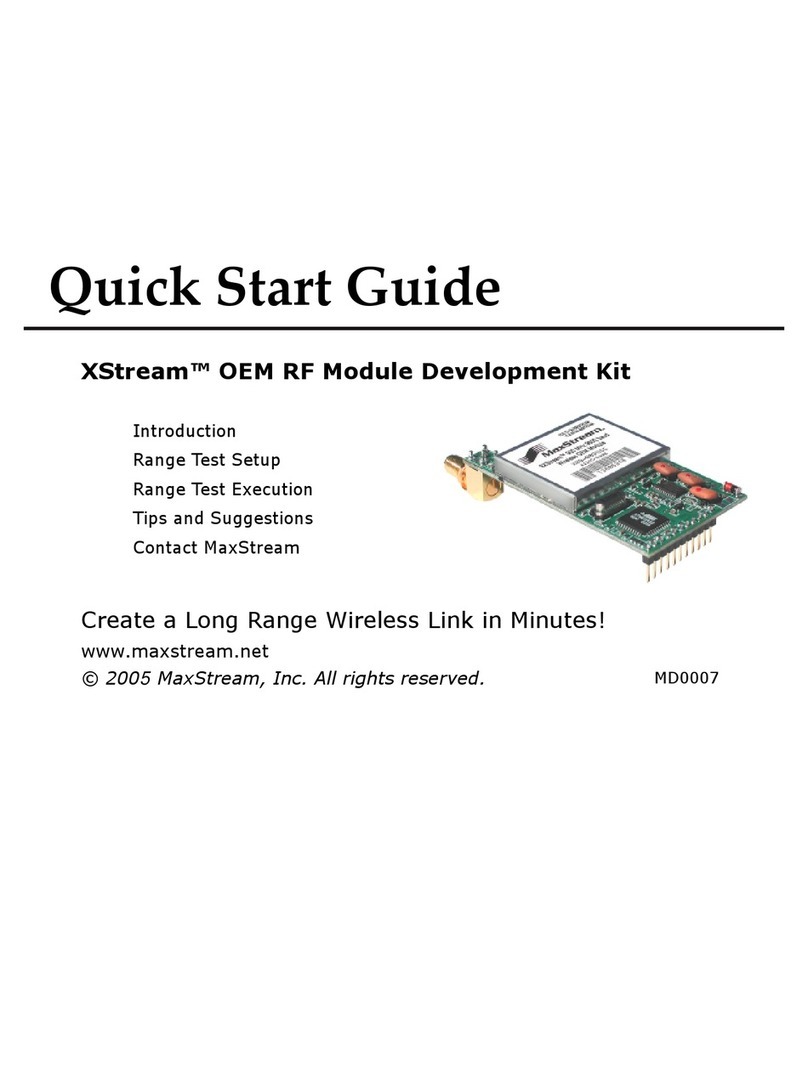
MaxStream Xbee User manual

Quick Start Guide
Create long range wireless links in minutes!
XBee™/XBee-PRO™ OEM Development Kits
www.maxstream.net
© 2006 MaxStream, Inc. All rights reserved. MD0026 [2006.04.25]
MaxStream
Introduction
Range Test Setup
Point-to-point Range Test
Point-to-multipoint Networks
Addressing Considerations
Introduction
This Quick Start Guide provides step-by-step instruction on how to setup wireless links
and test the modules’ ability to transport data over varying ranges and conditions. This
guide illustrates how to setup and run a point-to-point range test; then how to expand
into a point-to-multipoint topology.
Required Components
(2) OEM RF Modules (any combination of XBee & XBee-PRO Modules)
(1) USB Interface Board* (for interfacing between an RF module & host PC)
(1) RS-232 Interface Board (for looping data back to the base from a remote)
(1) PC (Windows 2000 or XP) with an available USB (or RS-232*) port.
Required installations: X-CTU Software & USB drivers (Note: Drivers for LINUX and Mac
OS X are provided on the CD, but the X-CTU Software will only run on Windows.)
Accessories (1 USB Cable, 1 Serial Loopback Adapter [RED] & 1 power supply)
* XBee Professional Developer Kits (XB24-PDK) contain four RS-232 boards. An RS-232
board (w/ RS-232 cable & power supply) can be used in lieu of the USB option.
Range Test Setup
Install X-CTU Software
Double-click "setup_X-CTU.exe" file and follow prompts of the installation screens.
This file is located on the MaxStream CD and under the 'Software' section of the
following web page: www.maxstream.net/support/downloads.php
The X-CTU Software interface is divided into the four following tabs:
• PC Settings - Setup PC serial com ports to interface with the RF module
• Range Test - Test the range of wireless links under varying conditions
• Terminal - Read/Set RF module parameters and monitor data communications
• Modem Configuration - Read/Set RF module parameters
Software Installations

Install USB Drivers (Hardware USB Bus & Virtual Com Port drivers)
The following steps were recorded while using the Windows XP operating system.
1. Verify the MaxStream CD is inserted into the CD drive.
2. Connect the USB development board to a PC using USB cable.
After the module assembly is detected by the PC, a “Found New Hardware
Wizard” dialog box should appear.
3. Select the ‘No, not this time’ option; then select the ‘Next’ button.
4. Select ‘Install from a specific list or location (Advanced)’ option; then select
the ‘Next’ button.
5. a. Select the ‘Search for the best driver in these locations’ option.
b. Check ‘Search removable media (CD-ROM...)’ box; then select ‘Next’.
The "Windows Logo Testing" alert box appears.
6. Select the ‘Continue Anyway’ button.
7. Select the ‘Finish’ button.
8. Repeat steps 2 through 6 to install the next driver.
9. Reboot the PC if prompted to do so.
Setup Point-to-point Wireless Data Link
1. Mount XBee/XBee-PRO Modules to the USB & RS-232 development boards.
The module mounted to the USB board will be referred to as the “BASE”.
The module mounted to the RS-232 board will be referred to as the “REMOTE”.
2. [Only if using modules that have the U.FL antenna connector]
Connect the RF Cable Assembly to the U.FL antenna connector and RPSMA
half-wave dipole antenna.
3. After installing the X-CTU Software and USB drivers, connect the BASE
module assembly to the PC using a standard USB cable [Figure 1].
4. Attach the Serial Loopback Adapter [red] to the female DB-9 connector of the
REMOTE module assembly.
The Serial Loopback Adapter configures the REMOTE to function as a repeater
by looping data back into the module for retransmission [Figure 1].
5. Power the REMOTE through the RS-232 development board’s power connector
using the power adapter included in the development kit.
The BASE is powered through its USB connection.
Hardware Setup
Figure 1. Hardware Setup
Host PC BASE
Loopback Adapter (Red)
REMOTE
USB Cable Whip, Chip or RPSMA
Antennas
Software Installations (continued)

Point-to-point Range Test
Run Range Test
PC Com Port
1. Launch the X-CTU Software:
(
Start --> Programs --> MaxStream --> X-CTU
)
Under the “PC Settings” tab [Figure 2], select the PC serial com port
from the list that will be used to connect to the BASE module assembly.
Before proceeding, verify the baud and data settings of the com port match
those of the RF module.
3. Select the “Range Test” tab. [Figure 3]
(Optional) Check the "RSSI" checkbox to enable its display.
Click the ‘Start’ button to begin the range test.
6. Move the REMOTE (with red Serial Loopback Adapter) away from the BASE
to find the maximum range of the wireless link.
2
4
5
Use the “PC Settings” and “Range Test” tabs of the X-CTU Software to:
• Setup a PC Serial Com Port for communications with the BASE module assembly
• Determine the range capabilities of the XBee/XBee-PRO Modules
The out-of-box default configuration of the module is optimal for running this range test.
5
4
Figure 3. Range Test tab
Start/(Stop) button
(Packet Information)
RSSI checkbox
RSSI stands for “Received Signal Strength
Indicator”
2
Figure 2. PC Se�ings tab
NOTE: Failure to enter AT Command Mode
is most commonly due to baud rate mismatch.
Ensure the ‘Baud’ setting on the “PC Settings”
tab matches the interface data rate of the
module [BD (Interface Data Rate) parameter =
9600 bps by default].

Phone: (801) 765-9885, Live Chat: www.maxstream.net, E-mail: [email protected]
Contact MaxStream (Office hours are 8am – 5pm U.S. Mountain standard time)
Point-to-multipoint topologies require that one BASE module be configured to operate in
Broadcast Mode [see ‘Addressing Considerations’ section]. REMOTE modules can operate
either in Broadcast or Unicast Mode. The figure below depicts a typical point-to-multipoint
network that contains one BASE (Broadcast Mode) and four REMOTES (Unicast Mode).
Point-to-multipoint Networks
Unicast Mode
By default, XBee/XBee-PRO Modules are configured to operate in Unicast Mode -
retries are enabled and receiving modules send an ACK (acknowledgement) of RF
packet reception to the transmitter. If the transmitting module does not receive an
ACK, it re-sends the RF data packet up to three times or until the ACK is received.
Default addressing parameters:
MY (16-bit Source Address) = 0
DL (Destination Address Low) = 0
DH (Destination Address High) = 0
Addressing Considerations
Broadcast Mode
For one RF module to communicate to many modules, one module (BASE) must be
configured to operate in Broadcast Mode. When in Broadcast Mode, retries and
acknowledgements are disabled. Broadcast Mode is enabled by setting Destination
Addresses as follows:
DL (Destination Address Low) = 0x00000000
DH (Destination Address High) = 0x0000FFFF
Refer to the product manual for more information regarding addressing.
Figure 4. Sample Point-to-multipoint Network Configuration
Host PC BASE
USB Cable
DH = 0
DL = 0xFFFF
MY = 0
REMOTE #1
DH = 0
DL = 0
MY = 1
REMOTE #2
DH = 0
DL = 0
MY = 2
REMOTE #3
DH = 0
DL = 0
MY = 3
REMOTE #4
DH = 0
DL = 0
MY = 4
Parameters Cited:
DH (Destination Address High)
DL (Destination Address Low)
MY (16-bit Source Address)
RF Module Configuration
To configure RF module parameters:
• Install X-CTU Software (& USB drivers if connecting to the host via a USB port)
• Setup a USB or RS-232 connection between the module and host PC [page 2]
• On the X-CTU “PC Settings” tab [Figure 2]: Verify com port and module settings
match; then select the PC com port that will be used to connect to the BASE
• On the X-CTU “Modem Configuration” tab: Select the ‘Read’ button, modify
parameters, then select the ‘Write’ button.
This is one of several configuration methods. Refer to the manual for more information.
Other manuals for Xbee
1
This manual suits for next models
1
Table of contents
Other MaxStream Microcontroller manuals
Popular Microcontroller manuals by other brands

ST
ST B-L462E-CELL1 user manual

Texas Instruments
Texas Instruments SimpleLink MSP432P4 Series Technical reference manual

Thundercomm
Thundercomm C40 Series quick start guide

Nations
Nations N32G43 Series user manual

Mediatek Labs
Mediatek Labs LinkIt 7687 HDK V30 user guide

Abov
Abov MC96F6432S Series user manual

GigaDevice Semiconductor
GigaDevice Semiconductor GD32450Z-EVAL user guide

Freescale Semiconductor
Freescale Semiconductor MC9S12C Family Reference manual

Vageo
Vageo RT-1 manual

Texas Instruments
Texas Instruments Hercules RM48 user guide

Thundercomm
Thundercomm TurboX CM6125 Hardware user manual

Atmel
Atmel AVR8015 Application note