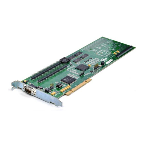
PEX 8616 RDK Hardware Reference Manual – Version 1.1
Copyright © 2009 by PLX Technology, Inc. All rights reserved ii
CONTENTS
0BNOTICE ....................................................................................................................................................... i
1BABOUT THIS MANUAL................................................................................................................................... i
6BREVISION HISTORY ..................................................................................................................................i
1.2BGeneral Information ..........................................................................................................................1
1.17BPEX 8616 Features...................................................................................................................2
1.28BPEX 8616 RDK Features ..........................................................................................................3
2.3BPEX 8616 RDK Hardware Architecture ............................................................................................4
2.1.129BPEX 8616 PCI Express Gen 2 Switch...................................................................................4
2.29BPEX 8616 RDK PCI Express Interfaces....................................................................................4
2.2.130BConfiguration Modules and Receptacle CM1........................................................................5
2.2.231BPCI Express Card Edge Connector P1 .................................................................................6
2.2.332BPCI Express Edge Card Connector SLOT 1 .........................................................................6
2.2.433BPCI Express Edge Card Connector SLOT 2 .........................................................................6
2.2.534BPCI Express Edge Card Connector SLOT 3 .........................................................................6
2.2.635B4X Mini-SAS Connector IP1..................................................................................................6
2.310BReference Clock Circuitry .........................................................................................................7
2.411BReset Circuitry...........................................................................................................................8
2.512BHot-Plug Circuits .......................................................................................................................8
2.5.136BParallel Hot-Plug Controller Circuit........................................................................................8
2.5.237BSerial Hot-Plug Controller Circuits.........................................................................................9
2.613BSerial EEPROM ......................................................................................................................10
2.714BI2C Interface ............................................................................................................................10
2.815BPower Distribution ...................................................................................................................11
2.916BLED Indicators.........................................................................................................................11
2.9.138BPort Link Status Indication (D17 – D20)..............................................................................12
2.9.239BFatal Error Indication (D24).................................................................................................12
2.9.340BPEX_INTA Interrupt Indication (D23) ..................................................................................12
2.9.441BPEX 8616 Voltage Level Monitoring (D10 – D11)...............................................................13
2.1017BGPIO Pins ...............................................................................................................................13
2.1118BReserved Pins.........................................................................................................................13
3.4BOn-Board Connectors, Switches, and Jumpers..............................................................................14
3.119BDIP Switches...........................................................................................................................14
3.1.142BSlot ID Selection (SW1) ......................................................................................................14
3.1.243BSerial Hot-Plug Signal and Control (SW2) ..........................................................................14
3.1.344BParallel Hot-Plug Signal and Control (SW3)........................................................................15
3.1.445BDC/DC Converter and Mode Controls (SW4)......................................................................15
3.1.546BUpstream Port Select (SW5)...............................................................................................16
3.1.647BPort Configuration and NT Upstream Port Select (SW6) ....................................................16
3.1.748BTest Mode Select (SW7) .....................................................................................................17
3.1.849BI2C Address and Other Mode Select (SW8) ........................................................................18
3.220BPush-Button Switches .............................................................................................................19
3.2.1Manual Reset# (S1) ............................................................................................................19
3.2.2Serial Hot-Plug Controller Attention Button (S2) .................................................................19
3.2.3Parallel Hot-Plug Controller Attention Button (S3) ..............................................................19
3.321BMidbus probe footprints (JP1 – JP2).......................................................................................19
3.422B2.5V Header (JP3) ..................................................................................................................21
3.523BJTAG Header (JP4).................................................................................................................21
3.624BI2C Port (JP5 – JP6) ................................................................................................................21
3.725BATX HD Power Connector (J1) ...............................................................................................22
3.826BReference Clock Header (J2)..................................................................................................22
