MAXTOOLS AR300 User manual

AR300
Air Reel · 8x12mm · 8+2mt
Manuale d’uso / User Manual / Notice d’utilisation / Betriebsanleitung / Manual del usuario

2
Tubo PVC
Diametro Tubo 8x12 mm
Lunghezza Tubo 8 + 2 m
Pressione Massima 12 bar
Temperature di Utilizzo -5°~ 45°
Dimensioni 360x330x160 mm
Peso 4 Kg
Caratteristiche Tecniche
Italiano

3
Misure di sicurezza
NORME GENERALI DI SICUREZZA
ATTENZIONE: Leggere attentamente le istruzioni e precauzioni prima di
assemblare, montare e usare il vostro arrotolatore, onde evitare danni
a persone e/o cose, conservare le istruzioni per ogni eventuale dubbio
futuro.
Precauzioni di sicurezza.
1. Prima dell’uso controllare che la pressione in ingresso non sia
superiore a quella consentita dal proprio arrotolatore.
2. Usare le dovute protezione agli occhi quando si assembla e si usa
l’arrotolatore.
3. Usare del sapone e dell’acqua per controllare le perdite (negli
arrotolatori ad aria).
4. Tenere i bambini lontani dall’area di lavoro.
5. Non tirare o strappare il tubo o il cavo.
ATTENZIONE
L’aria o l’acqua compressa a diretto contatto con la pelle possono
provocare gravi danni personali
Italiano

4
Installazione dell’arrotolatore
Per un montaggio a soffitto: Installare l’arrotolatore a non meno di 3
metri di altezza.
È necessario munirsi dell’appropriata attrezzatura per il montaggio
dell’arrotolatore.
1. L’arrotolatore è provvisto di 3 fori di 10.5 mm per il montaggio
su una superficie liscia. Nella figura 1 è rappresentata la corretta
locazione dei 3 fori necessari per il montaggio.
2. Usare i 3 fori sulla base per montare l’arrotolatore nella posizione
desiderata, assicurandosi che i sistemi di fissaggio siano appropriati
all’uso.
3. Applicare del nastro in teflon o del sigillante per raccordi, quindi
collegare l’alimentazione aria/acqua. L’altra estremità del tubo può
essere collegata all’attrezzatura desiderata. Quindi controllare per
eventuali perdite d’aria/acqua.
4. Per regolare lo STOPPER (fig. 2) alla lunghezza desiderata, estrarre
il tubo e bloccarlo nella posizione desiderata. Allentare le viti dello
STOPPER, posizionarlo nel punto desiderato, quindi stringere
nuovamente le viti.
Fig. 1
Italiano

5
Uso dell’arrotolatore
1. Controllare il corretto funzionamento estraendo lentamente il tubo,
ad ogni mezzo giro del tamburo si sentirà una serie di “click”.
2. Estrarre il tubo e lasciarlo lentamente rientrare, dopo aver sentito il
primo o secondo “click”.
3. Per il riavvolgimento: estrarre lentamente il tubo fino all’ultimo
“click”, quindi lasciare che il tubo rientri lentamente nel tamburo
trattenendolo con le mani.
4. Periodicamente controllare l’arrotolatore per eventuali usure,
danneggiamenti o perdite. Sostituire ogni eventuale particolare
danneggiato.
Fig. 2
Italiano
Parete Soffitto
Stopper
Stopper

6
Sostituzione anello di tenuta
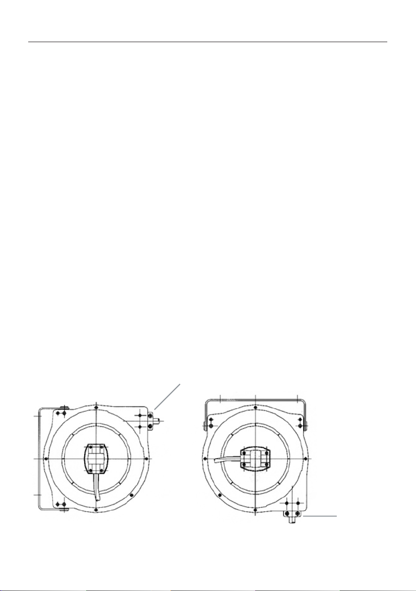
Scollegare l’alimentazione aria/acqua, togliere il coperchio in plastica
(particolare 2) e il giunto girevole (particolare 3), rimuovere l’anello di
tenuta e sostituirlo con uno nuovo, riassemblare il giunto e il coperchio.
Ricollegare l’alimentazione aria/acqua, e controllare per eventuali
perdite.
Garanzia
1. Il produttore garantisce l’arrotolatore da eventuali difetti di materiale
o di funzionamento per un periodo di 12 mesi dalla data di acquisto.
2. Tubo (se fornito), anelli di tenuta, rulli in plastica, stopper in gomma,
sono considerati particolari usurabili, e quindi non soggetti a
garanzia.
3. L’obbligo del produttore è limitato alla sostituzione o riparazione
del materiale difettoso durante il periodo di garanzia, il prodotto
va riconsegnato in PORTO FRANCO al rivenditore o al centro di
assistenza autorizzato.
4. La garanzia non copre i danni causati accidentalmente o provocati
dal cattivo uso e/o un’errata installazione.
ATTENZIONE
Trattenere sempre il tubo durante il riavvolgimento, in caso contrario
si può andare in contro a pericolosi danneggiamenti e/o infortuni
Italiano

7
Esploso arrotolatore e ricambi
N° parte Descrizione Q.tà
1 Viti ST4.2 16 12
2 Coperchio in plastica 1
3 Giunto girevole 1
4 Anello di tenuta 2
5 Bullone 2
6 Viti ST4.2 19 10
7 Carter esterno 1
8 Rulli 2
9 Spina ferma il tubo 1
10 Tamburo 1
11 Raccordo 1
12 Molla 1
13 Tamburo 1
14 Asse centrale 1
N° parte Descrizione Q.tà
15 Nottolino di arresto 1
16 Perno nottolino 1
17 Molla 1
18 Supporto arrotolatore 1
19 Carter esterno 1
20 Perno 2
21 Dado 2
22 Tubo 1
23 Dado 2
24 Bullone 2
25 Blocco tubo 2
26 Blocco tubo in gomma 1
27 Tubo 1
Italiano

8
Hose PVC
Hose diameter 8x12 mm
Hose length 8 + 2 m
Maximum pressure 12 bar
Operating temperatures -5°~ 45°
Sizes 360x330x160 mm
Weight 4 Kg
Technical Specifications
English

9
Safety measures
GENERAL SAFETY REGULATIONS
NOTE: Read both instructions and precautions carefully before
assembling,mounting and using your hose reel,in order to avoid damage
to people or/and things and keep the instructions for any further doubt.
Safety precautions.
1. Before use, make sure the incoming pressure does not exceed the
one allowed by your hose reel.
2. When assembling and using your hose reel, take the appropriate
precautions to protect your eyes.
3. Use soap and water to test for leaks (in air reels).
4. Keep children away from the working area.
5. Do not pull or rip the hose and the cable.
WARNING
Compressed air and water contact with your skin can cause
serious personal damage
English

10
Installation of the hose reel
In case of ceiling mounting: install the hose reel at a height of not less
than 3 meters.
To mount the hose reel you need the appropriate equipment.
1. The hose reel is provided with 3 holes of 10.5 mm for assembling
on a smooth surface.
2. Figure 1 shows the correct positioning of the holes necessary for
assembling.
3. Use the 3 holes in the support base to mount the hose reel in the
desired position. Be sure that the fastening systems are suitable for
the purpose.
4. Apply either teflon tape or some adequate sealant for fittings and
then connect the air/water supply. The other end of the hose can be
connected with the desired equipment. At this point, check for any
air/water leakages.
5. To regulate the STOPPER (fig. 2) at the desired length, extract the
hose and block it in the desired position. Loosen the screws of the
STOPPER, place it in the required position and then tighten the
screws again.
Fig. 1
English

11
Use of the hose reel
1. Verify the correct functioning by pulling out the hose; at every half
turn of the drum you will hear a series of clicks.
2. Pull out the hose and then let it retract slowly after hearing the first
and the second click.
3. When you want to rewind, pull out the hose until you hear the last
click and, then, let the hose retract slowly into the drum by holding
with your hands.
4. Periodically check the hose reel for any wear, damage or leakage.
Replace any damaged part.
Fig. 2
Wall Ceiling
Stopper
Stopper
English

12
Replacement of the sealing ring
Disconnect the air/water supply, remove the plastic cover (part N° 2)
and the swivel joint (part N°3), remove the sealing ring and replace
it with a new one; then, reassemble both sealing ring and cover and
reconnect the air/water supply while checking for any leakages.
Warranty
1. The hose reel is warranted by the producer against any defect of
the material, or the functioning of the product for a period of 12
months from purchase date.
2. Being particularly subject to wear, hose (if provided), seal rings,
plastic rollers, rubber stoppers, do not fall under warranty.
3. The producer’s liability is limited to the substitution or repair of the
defective material under warranty. The product must be returned
FREE PORT either to the dealer or to the authorized assistance
center.
4. Warranty does not cover damage accidentally caused or provoked
by misuse and/or wrong installation.
WARNING:
Always hold the hose while rewinding; if not, you could run the risk
of serious damage and/or injuries
English

13
Exploded view of the hose reel and its spare parts
Part number Description Qty
1 ST4.2 16 tapping screw 12
2 Plastic cover 1
3 Swivel joint 1
4 Sealin ring 2
5 Bolt 2
6 ST4.2 19 tapping screws 10
7 Outer casing 1
8 Reels 2
9 Pipe clip plug 1
10 Drum 1
11 Connection 1
12 Spring 1
13 Drum 1
14 Centerline 1
Part number Description Qty
15 Locking pawl 1
16 Pin of the pawl 1
17 Spring 1
18 Hose reel support 1
19 Outer casing 1
20 Pin 2
21 Nut 2
22 Hose 1
23 Nut 2
24 Bolt 2
25 Hose lock 2
26 Rubber stopper 1
27 Hose 1
English

14
Tuyau PVC
Diamètre tuyau 8x12 mm
Longueur tuyau 8 + 2 m
Pression maximum 12 bar
Température d’utilisation -5°~ 45°
Dimensions 360x330x160 mm
Poids 4 Kg
Caractéristiques techniques
Français

15
Mesures de sécurité
RÈGLES GÉNÉRALES DE SÉCURITÉ
ATTENTION: lire attentivement les instructions et les précautions de
sécurité avant d’assembler, de monter et d’utiliser l’enrouleur, afin
d’éviter tout dommage aux personnes ou aux choses, conserver cette
notice d’utilisation pour toute consultation future.
Précautions de sécurité.
1. Avantutilisation,vérifierquela pressiond’entrée n’estpassupérieure
à celle autorisée par l’enrouleur.
2. Adopter les équipements de protection des yeux nécessaires lors du
montage et de l’utilisation de l’enrouleur.
3. Utiliser du savon et de l’eau pour vérifier les fuites (pour les
enrouleurs à air).
4. Tenir les enfants loin de la zone de travail.
5. Ne pas tirer ni arracher le tuyau ou le câble.
ATTENTION
L’air ou l’eau comprimé(e) peut provoquer des blessures graves
par contact direct avec la peau
Français

16
Installation de l’enrouleur
Pour le montage au plafond : installer l’enrouleur à une hauteur d’au
moins 3 mètres.
Il est nécessaire d’utiliser un outillage approprié pour le montage de
l’enrouleur.
1. L’enrouleur est muni de 3 trous de 10,5 mm pour le montage sur
une surface lisse. La figure 1 illustre l’emplacement correct des 3
trous requis pour le montage.
2. Utiliser les 3 trous sur la base pour monter l’enrouleur dans la
position souhaitée, en s’assurant que les systèmes de fixation sont
appropriés à l’utilisation.
3. Appliquer du ruban en téflon ou du mastic pour raccords, puis
brancher l’alimentation d’air/eau. L’autre extrémité du tuyau peut
être branchée à l’équipement souhaité. Vérifier ensuite l’absence
de fuites d’air/d’eau.
4. Pour régler la BUTÉE D’ARRÊT (fig. 2) à la longueur souhaitée,
extraire le tuyau et le bloquer dans la position désirée. Desserrer les
vis de la BUTÉE D’ARRÊT, la placer au point souhaité, puis resserrer
les vis.
Fig. 1
Français

17
Utilisation de l’enrouleur
1. Vérifier le bon fonctionnement en tirant lentement le tuyau, une
série de déclics se fera entendre à chaque demi-tour du tambour.
2. Extraire le tuyau et le laisser se ré-enrouler lentement, après avoir
entendu le premier ou le deuxième déclic.
3. Pour le ré-enroulement : tirer lentement le tuyau jusqu’au dernier
déclic, puis le laisser se ré-enrouler lentement dans le tambour, en
le retenant avec les mains.
4. Vérifier régulièrement l’enrouleur pour détecter toute présence
d’usure, de dommage ou de fuite. Remplacer toutes les pièces
endommagées.
Fig. 2
Mur Plafond
Butée d’arrêt
Butée d’arrêt
Français

18
Remplacement de la bague d’étanchéité
Débrancher l’alimentation d’air/eau, retirer le couvercle en plastique
(détail 2) et le joint tournant (détail 3), retirer la bague d’étanchéité et la
remplacer par une neuve, remonter le joint et le couvercle. Rebrancher
l’alimentation d’air/eau et vérifier l’absence de fuites.
Garantie
1. Le fabricant garantit l’enrouleur contre tout défaut matériel ou de
fonctionnement pendant une période de 12 mois à compter de la
date d’achat.
2. Le tuyau (s’il est fourni), les bagues d’étanchéité, les rouleaux en
plastique, les butées d’arrêt en caoutchouc sont considérés comme
des pièces sujettes à usure, par conséquent ils ne sont pas couverts
par la garantie.
3. L’obligation du fabricant est limitée au remplacement ou à la
réparation du matériel défectueux pendant la période de garantie,
le produit doit être retourné en PORT GRATUIT au revendeur ou au
centre d’assistance technique autorisé.
4. La garantie ne couvre pas les dommages accidentels ou causés par
une mauvaise utilisation ou une installation incorrecte.
ATTENTION
Toujours tenir le tuyau pendant le ré-enroulement pour éviter tout
risque d’endommagement ou d’accident
Français

19
Vue éclatée enrouleur et pièces de rechange
N° pièce Description Q.té
1 Vis ST4.2 16 12
2 Couvercle en plastique 1
3 Joint tournant 1
4 Bague d’étanchéité 2
5 Boulon 2
6 Vis ST4.2 19 10
7 Boîtier extérieur 1
8 Rouleaux 2
9 Goupille d’arrêt tuyau 1
10 Tambour 1
11 Raccord 1
12 Ressort 1
13 Tambour 1
14 Axe central 1
N° pièce Description Q.té
15 Cliquet d’arrêt 1
16 Axe cliquet 1
17 Ressort 1
18 Support enrouleur 1
19 Boîtier extérieur 1
20 Goujon 2
21 Écrou 2
22 Embout tuyau 1
23 Écrou 2
24 Boulon 2
25 Butée d’arrêt tuyau 2
26 Butée d’arrêt tuyau en caoutchouc 1
27 Embout tuyau 1
Français

20
Schlauch PVC
Schlauchdurchmesser 8x12 mm
Schlauchlänge 8 + 2 m
Höchstdruck 12 bar
Betriebstemperaturen -5°~ 45°
Größen 360x330x160 mm
Gewicht 4 Kg
TechnischeDaten
Deutsch
Table of contents
Languages:
Other MAXTOOLS Tools manuals
Popular Tools manuals by other brands

Stahlwille
Stahlwille MULTIPOWER MP300 Instructions for use

Dynello
Dynello Accu Winder quick start guide

Atlas Copco
Atlas Copco PB 14 D quick start guide

Tohnichi
Tohnichi RNTD Operating instruction

Eurolube Equipment
Eurolube Equipment S10 Series Service guide

BGS technic
BGS technic 8716 instruction manual

Parkside
Parkside PDST 10 B3 Translation of the original instructions

Skil
Skil 1735 Original instructions

EINHELL
EINHELL DFP 210 Operating and maintenance instructions

Porter-Cable
Porter-Cable 42690 quick start guide

ReelCraft
ReelCraft UR82000 OLB operating instructions

MachineryHouse
MachineryHouse K8735 instruction manual