MAXX DIGM MAXX DS200 Series User manual

USER GUIDE
MAXX DS200 series

Computer and Robotics Aided Manufacturing
2
Copyright © 2019 by Maxx Digm, Inc
All rights reserved. This manual or parts thereof may not be reproduced in any form, stored in
any retrieval system, or transmitted in any form by any means—electronic, mechanical,
photocopy, recording, or otherwise—without prior written permission of the publisher, except
as provided by United States of America copyright law. For permission requests, write to the
publisher, at "Attention: Permissions Coordinator," at the addresses below.
Maxx Digm, Inc
Address 3265 Kifer Road, Santa Clara, CA 95051
Tel408-462-9608
E-mail[email protected]
Robots and Design, Ltd.
Address Pangyo-ro 700, E-707, Seongnam-City, Gyunggi-do
Korea 13516
Tel +82-31-708-2684
Fax +82-31-706-9093
E-mail [email protected]

Computer and Robotics Aided Manufacturing
3
Contents
I. EPNC Installation ................................................................................................................................................5
Program Installation...........................................................................................................................................5
II. Description of EPNC .........................................................................................................................................6
2.1 Initialization window ...................................................................................................................................6
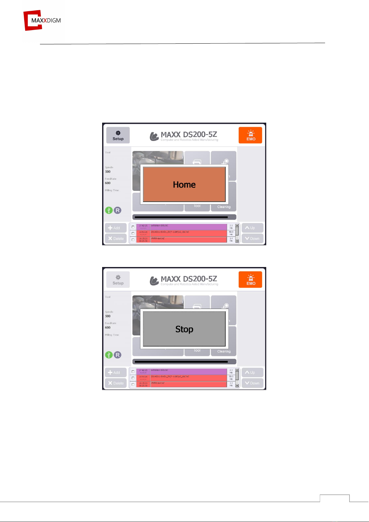
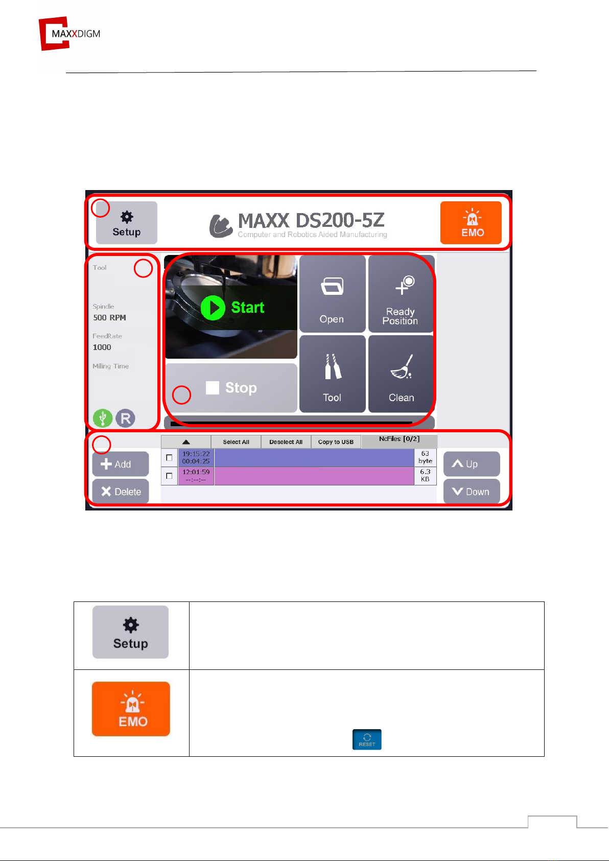
2.2 Main window..................................................................................................................................................7
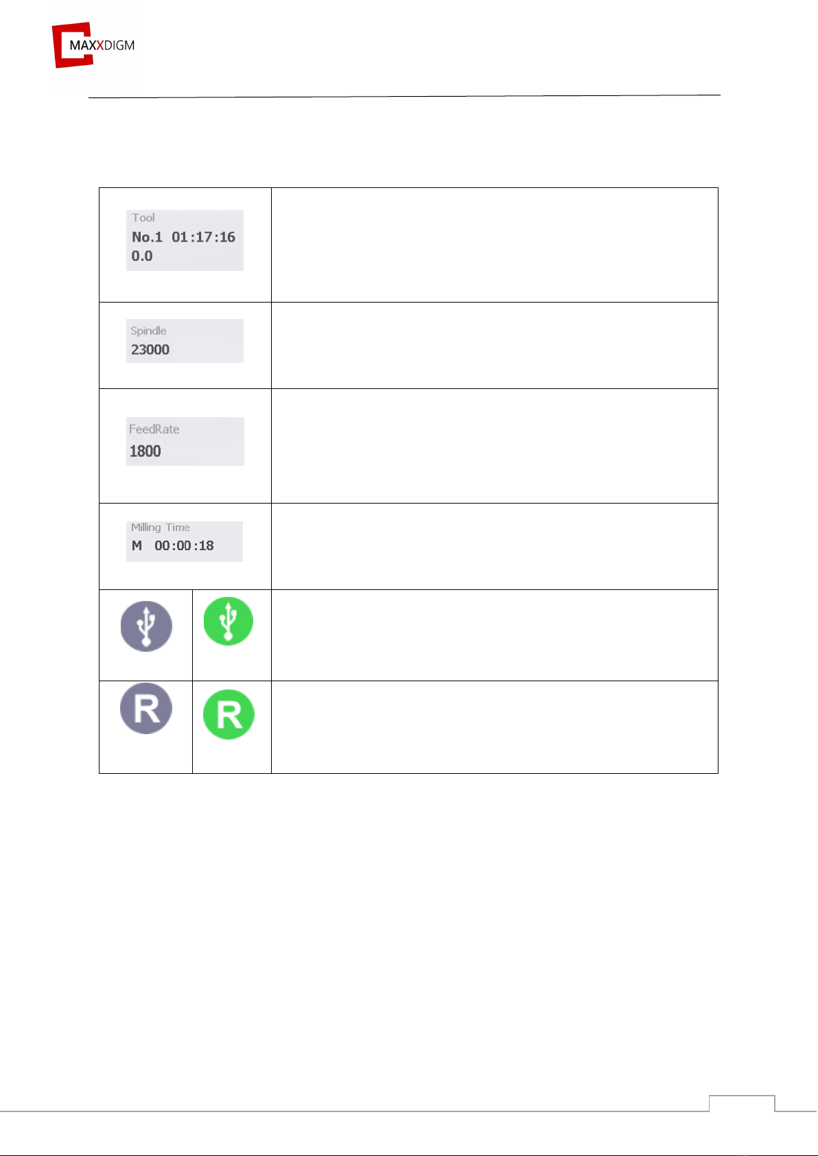
2.2.1 Functions of main window.................................................................................................................7
2.3 Setup............................................................................................................................................................... 14
2.3.1 Entering setup..................................................................................................................................... 14
2.3.3 Tool......................................................................................................................................................... 23
2.3.4 Term....................................................................................................................................................... 25
2.3.5 Option.................................................................................................................................................... 26
2.3.6 I/O ........................................................................................................................................................... 28
2.3.7 Log .......................................................................................................................................................... 29
2.3.8 System.................................................................................................................................................... 30
III. Milling................................................................................................................................................................ 31
3.1 Machine power............................................................................................................................................ 31
3.2 Milling preparation................................................................................................................................... 31
3.2.1 Mounting workpiece ......................................................................................................................... 31
3.2.2 Tool......................................................................................................................................................... 35
3.2.3 NC file.................................................................................................................................................... 41
3.2.4 Maxxlink............................................................................................................................................... 41
IV. Maintenance..................................................................................................................................................... 45
4.1 Maintenance precautions......................................................................................................................... 45
4.2 Daily maintenance...................................................................................................................................... 45
4.2.1 Cleaning ................................................................................................................................................ 45
4.2.2 Dummy tool.......................................................................................................................................... 46

Computer and Robotics Aided Manufacturing
4
4.2.3 Cleaning mode..................................................................................................................................... 47
4.3 Periodic maintenance................................................................................................................................ 50
4.3.1 Replacing consumable parts........................................................................................................... 52
4.3.2 Spindle warm-up........................................................................................................................... 53
4.3.3 Spindle cleaning............................................................................................................................ 53
4.3.4 Auto Calibration................................................................................................................................. 54
4.3.5 Collet tightening ................................................................................................................................. 71
V. Trouble shooting .............................................................................................................................................. 72
5.1 Restart milling........................................................................................................................................ 72
5.2 Air pressure sensor setting................................................................................................................. 75
5.3 Removing ATC push limit.................................................................................................................. 77

Computer and Robotics Aided Manufacturing
5
I. EPNC Installation
Program Installation
To install the program, copy PNC folder. PNC folder is organized as below.
①<Bin> Folder
<Bin> contains necessary DLL files to execute Pnc.exe and the program. Below is
the description of main executable file and DLL.
File name
Description
Remarks
PNC.exe
PNC Program file
PComm32.dll
DLL files to manage Pmac Controller
②<Config> Folder
<Config> contains necessary setting files to execute PNC program. Detailed
description for each setting file is in “8. Config file” in <Config> folder.
③<Log> Folder
<Log> records all activities of the machines and save them in Pnclog.db file. To
check contents of log files, special viewer is required.
④<NcFiles> Folder
<NcFiles> is to save NC files for milling. It can be used to copy files from outside.
⑤<Resource> Folder
<Resource> is to save resources that will be used in the program. It is not allowed
to delete or change names of files saved in the folder.

Computer and Robotics Aided Manufacturing
6
II. Description of EPNC
2.1 Initialization window
Initializing window is shown as below. The machine is initialized by pressing the “Home”
button.
Initial window of EPNC
EPNC starts initializing when “HOME” is clicked.
The window flashes for about 15 seconds while initializing.
It stops initializing when “STOP” is clicked.

Computer and Robotics Aided Manufacturing
7
2.2 Main window
Once initialization is completed, main window will appear.
Machine’s model is written on the top and commonly used functions are shown on the main
window.
2.2.1 Functions of main window
2.2.1.1 Operational setting & EMO
Function of setup and EMO is shown as below.
General setting and changing offset values
- Refer to p.13 Setup
EMO (Emergency) Button
- For immediate stop
- Emergency stop for hardware
- It changes to “RESET” once clicked
1
2
3
4

Computer and Robotics Aided Manufacturing
8
2.2.1.2 Machine status
It shows machine’s status and activated condition.
Tool Number
- Overall information of the clamped tool.
- Indicating tool number and work hour [hour : minute :
second].
Spindle RPM
- Amount of spinning rounds per minute (Max: 60,000rpm).
FeedRate (mm/min)
- The rate at which the tool has moved at a constant operating
cycle or time.
(moving speed of spindle)
Milling Time
- Amount of time it takes to finish milling [hour : minute :
second].
Deactivated
Activated
USB
- Indicating the presence of USB.
Deactivated
Activated
Remote program
-Indicating the presence of remote processing program that use
LAN network (Maxx Link).

Computer and Robotics Aided Manufacturing
9
2.2.1.3 Commonly used functions
Below is commonly used functions that are essential in operating the machine.
Start
- Initialize the selected NC file.
- Once clicked, it changes to “PAUSE” and stops
the milling process.
- Can resume the milling process by pressing “PAUSE” again.
Stop
- It will be activated after starting NC file.
- Stop the milling process of the current selected NC file
- Emergency stop of software.
Open
- Open selected NC file.
Ready Position
- Spindle and stage move to preset position.
Tool
- Below functions are shown when “Tool” is clicked.
* Collet Open / Close
To open and close collet.
The name of the button will change
depending the current state.
Tool number resets when collet is opened.
* ATC (Auto Tool Changer) (*DS200-
4W/4WA)
To open and close ATC door.
The name of the button will change
depending the current state.

Computer and Robotics Aided Manufacturing
10
* Return Tool
Returns the tool in the spindle collet to ATC
* Settings
Cleaning Mode
DS200-5Z
To clean floor of milling room.
It is recommended to use with brush to dust inside of milling
room.
DS200-4W / 4WA
To operate coolant for cleaning.
Connect cleaning hose to sprinkle coolant in milling room.
Be careful not to spread it to bellows behind spindle.
Collet has to clamp a tool while cleaning (preventing internal
inflow)
Milling status
Represents the current milling status in green color (%).

Computer and Robotics Aided Manufacturing
11
2.2.1.4 NC File
Displays information related to NC file and each functions are as shown below.
①Select file
②Milling start time / milling time
③NC file name
④NC file size
⑤▲: to show all the list of NC file
⑥Select All
⑦Deselect All
⑧Copy to USB: to copy NC files to USB
Add
- Adding NC file to embedded PC.
After inserting USB, click to create the following window
Refresh the list in USB
Select all NC files in USB

Computer and Robotics Aided Manufacturing
12
Unselect NC file
Copy NC file from USB to embedded PC
Quit
Delete
Check and click in the NC file list to delete the selected file
Move NC file
It is to change order of NC files.
Click ③ NC file name (EXAMPLE.NC → EXAMPLE.NC)
“Up” moves selected files upwards.
“Down” moves selected files downwards.
☞ Compatible USB
Below is a list of USB format that are compatible with the machine OS, Microsoft Embedded
CE6.0.
FAT16, FAT32, exFAT

Computer and Robotics Aided Manufacturing
13
➔ If USB is not compatible with the machine, please change the USB format by following
below instruction.
※ To format USB
1) Connect USB to a computer
2) Click on “my computer”
3) Right click on USB and click “Format (A)”
4) Click “File System” to select the file system that is compatible with the machine.
Do not select “Quick Format” under “Format option”.
5) Once the format has completed successfully, USB can be used.

Computer and Robotics Aided Manufacturing
14
2.3 Setup
2.3.1 Entering setup
Set up mode is a function that sets the parameters required for a program to operate
accurately and effectively.
Click on the “set up” button in the main menu to display the password screen as shown
below, allowing entry into three modes (each mode with different working permissions)
1) User P/W -> ENT (User mode)
2) Manager P/W (1234) -> ENT (Manager mode)
3) RND P/W (100321) -> ENT (RND mode)
Click to not enter password when re-entering setup

Computer and Robotics Aided Manufacturing
15
2.3.2 Teaching
2.3.2.1 Functions of teaching
①Coordinate and offset display.
Coordinate offset, teaching point and option.
②Axis jog and jog shortcut button.
③Opening and saving changed values.
• Download to Controller – save changed coordinates to controller.
• Save to File- save changed coordinates to PC memory.
• Load from File- display coordinates saved in PC memory.
• Auto Calibration (*refer to 2.3.2.5)
①
②
③

Computer and Robotics Aided Manufacturing
16
2.3.2.2 Coordinate offset & Teaching point
The offset values of the coordinate system used by the equipment can be stored by axis, and
the position of the various tools and system parameters can be saved.
Coordinate Offset
Displays coordinates for each position.
Name
Description
Remarks
G53
Motor coordinates.
Coordinates for each axis is based on motor’s origin.
G54-59
Work coordinates

Computer and Robotics Aided Manufacturing
17
Teaching Point
Managing the registration of basic coordinates for each action of the equipment.
Name
Description
Remarks
Tool1-8
Position of tool 1-8
Ready Position
Coordinates indicating preset position of spindle
Tool Sensing Up
Coordinates for tool to move in fast speed to tool
sensor
Tool Sensing Down
Distance between tool and sensor

Computer and Robotics Aided Manufacturing
18
2.3.2.3 Option
To manage option data.
Option
Description
Remarks
ZAxis Offset Origin
Distance between probing sensor (tool length
adjustment sensor) and milling origin in millimeter.
Tool Sensing High Speed
High speed for tool sensing measurement
Tool Sensing Low Speed
Slow speed for tool sensing measurement
Tool Sensing Margin
Acceptable range in tool length before and after
milling.
Tool Pocket Put offset
Spindle returns a tool after it moves to Z-axis as
offset amount from tool teaching position.

Computer and Robotics Aided Manufacturing
19
2.3.2.4 Jog
Use the +/- buttons on each motor shaft to move the motor (stage movement)
G53
- Displays coordinates being used (coordinates
based on motor)
0.000
- Indicates current coordinates of each axis
+ - (Symbol)
- Indicating the directions for each axis
- It is indicated as + - or + -
+ - changes into red when exceeding the limit.
Step
- To move preset amount only.
Cont. (Continuous)
- To move continuously.
0.01mm
- To select moving amount in “Step” mode (range
0.01~2.00mm)

Computer and Robotics Aided Manufacturing
20
X±, Y±, Z± (Jog moving button)
- To move stage in X, Y and Z axis direction.
Check “Step”, “Cont.”, and “moving amount”
before moving.
A/B Axis Jog
- To move A and B axis.
G53~G54
- To select coordinates
Spindle Clamp / Unclamp
- To open/close spindle collet
- Change according to current state
M28 / M29
- To operate vacuum or pump required for dry/wet
milling.
- Once clicked, it changes to M29
SRV-OFF
- Servo motor off
▲ 100% ▼
- To control moving speed of jog (Max. 100%)
This manual suits for next models
1
Table of contents
Popular Dental Equipment manuals by other brands

SILMET
SILMET ProVeneer Step by step manual guide

M+W Dental
M+W Dental select SUPERLITE POWER PEN Instructions for use

Dentsply Neytech
Dentsply Neytech Prime&Bond NT Instructions for use

DentalEZ
DentalEZ Star Titan Low-Speed manual

Qilive
Qilive Q.7692 user manual

KaVo
KaVo MASTERmatic LUX M07 L Instructions for use

Donaldson
Donaldson BOFA DentalPRO Xtract 200 user manual

Vatech
Vatech PAX Duo3D installation manual

Dabi Atlante
Dabi Atlante COBRA CONTRA ANGLE Series owner's manual

Straumann
Straumann 049.810V4 Instructions for use

Amanngirrbach
Amanngirrbach Ceramill mindserve manual

Carestream DENTAL
Carestream DENTAL CS 1500 user guide