manuals.online logo
Brands
  1. Home
  2. •
  3. Brands
  4. •
  5. Mayr
  6. •
  7. Control Unit
  8. •
  9. Mayr 0802459 Quick start guide

Mayr 0802459 Quick start guide

Polígono Industrial O Rebullón s/n. 36416 - Mos - España - [email protected]
Servicio de Att. al Cliente
+34 986 288118
Polígono Industrial O Rebullón s/n. 36416 - Mos - España - [email protected]
Servicio de Att. al Cliente
+34 986 288118
Installation and Operational Instructions for
half-wave and bridge rectifiers Type 02_.000.6 (B.02+0006.EN)
Chr. Mayr GmbH + Co. KG
Eichenstraße 1, D-87665 Mauerstetten, Germany
Tel.: +49 8341 804-0, Fax: +49 8341 804-421
, E-Mail:
14/06/2016 GC/TH/GF
Page 1 of 4 your reliable partner
11
Guidelines on the Declaration of Conformity
A conformity evaluation has been carried out for the product in terms of the EU Low Voltage Directive
2014/35/EU and the Electromagnetic Compatibility (EMC) Directive 2014/30/EU. The Declaration of Confor-
mity is laid out in writing in a separate document and can be requested if required.
Guidelines on the EMC Directive (2014/30/EU)
The product cannot be operated independently according to the EMC directive.
Only after integration of the product into an overall system can this be evaluated in terms of the EMC.
For electronic equipment, the evaluation has been verified for the individual product in laboratory conditions,
but not in the overall system.
Guidelines on the Machinery Directive (2006/42/EC)
The product is a component for installation into machines according to the machinery directive 2006/42/EC.
The product can fulfil the specifications for safety-related applications in coordination with other elements.
The type and scope of the required measures result from the machine risk analysis.
The product then becomes a machine component and the machine manufacturer assesses the conformity
of the safety device to the directive. It is forbidden to start use of the product until you have ensured that the
machine accords with the regulations stated in the directive.
Guidelines on the ATEX Directive
Without a conformity evaluation, this product is not suitable for use in areas where there is a high danger of
explosion. For application of this product in areas where there is a high danger of explosion, it must be clas-
sified and marked according to directive 2014/34/EU.
Safety and Guideline Signs
DANGER
Immediate and impending danger, which
can lead to severe physical injuries or to
death.
CAUTION
Danger of injury to personnel and damage
to machines.
Guidelines on important points.
General Safety Guidelines
DANGER
Danger of death! Do not touch voltage-
carrying lines and components.
Danger
Danger of burns when touching hot
surfaces
CAUTION • Danger from devices caused by short-
circuits and earth short-circuits at the
terminals
• Electronic devices cannot be guaranteed
fail-safe.
During the risk assessment required when designing the
machine or system, the dangers involved must be evaluated
and removed by taking appropriate protective measures.
To prevent injury or damage, only professionals and spe-
cialists are allowed to work on the devices. They must be
familiar with the dimensioning, transport, installation, initial
operation, maintenance and disposal according to the rele-
vant standards and regulations.
Before product installation and initial opera-
tion, please read the Installation and Opera-
tional Instructions carefully and observe the
Safety Regulations. Incorrect operation can
cause injury or damage.
Only carry out installation, maintenance and
repairs in a de-energised, disengaged state
and secure the system against inadvertent
switch-on.
11
Polígono Industrial O Rebullón s/n. 36416 - Mos - España - [email protected]
Servicio de Att. al Cliente
+34 986 288118
Polígono Industrial O Rebullón s/n. 36416 - Mos - España - [email protected]
Servicio de Att. al Cliente
+34 986 288118
Polígono Industrial O Rebullón s/n. 36416 - Mos - España - [email protected]
Servicio de Att. al Cliente
+34 986 288118
A
C
E
ØD
19
5
B
Installation and Operational Instructions for
half-wave and bridge rectifiers Type 02_.000.6 (B.02+0006.EN)
Chr. Mayr GmbH + Co. KG
Eichenstraße 1, D-87665 Mauerstetten, Germany
Tel.: +49 8341 804-0, Fax: +49 8341 804-421
, E-Mail:
14/06/2016 GC/TH/GF
Page 2 of 4 your reliable partner
22
Application
Rectifiers are used to connect DC consumers to alternating
voltage supplies, for example electromagnetic brakes and
clutches (ROBA-stop®, ROBA-quick®, ROBATIC®), elec-
tromagnets, electrovalves, contactors, switch-on safe DC
motors, etc.
Function
The AC input voltage (VAC) is rectified (VDC) in order to
operate DC voltage units. Also, voltage peaks, which occur
when switching off inductive loads and which may cause
damage to insulation and contacts, are limited and the con-
tact load reduced.
Electrical Connection (Terminals)
1 + 2 Input voltage
3 + 4 Connection for an external switch for DC-side swit-
ching
5 + 6 Coil
7 – 10 Free nc terminals (only for Size2)
When connecting to PELV, only for
overvoltage category II
Intended Use
mayr®-rectifiers have been developed, manufactured
and tested as electronic equipment in compliance with
the DIN EN 50178 standard and in accordance with the
EU Low Voltage Directive. During installation, operation
and maintenance of the product, the requirements for the
standard must be observed. mayr®-rectifiers are for use in
machines, systems and devices and must only be used in
the situations for which they are ordered and confirmed.
The products are designed for installation into electrical
control cabinets and terminal boxes. Using them for any
other purpose is not allowed.
Dimensions (mm)
Accessories: Mounting bracket set for 35 mm rail acc.
EN 60715: Article No. 1803201
Sizes A B C ØD E
1 34 30 25 3.5 4.5
2 54 30 44 4.5 5.0
3/4 64 30 54 4.5 5.0
22
Polígono Industrial O Rebullón s/n. 36416 - Mos - España - [email protected]
Servicio de Att. al Cliente
+34 986 288118
Polígono Industrial O Rebullón s/n. 36416 - Mos - España - [email protected]
Servicio de Att. al Cliente
+34 986 288118
Installation and Operational Instructions for
half-wave and bridge rectifiers Type 02_.000.6 (B.02+0006.EN)
Chr. Mayr GmbH + Co. KG
Eichenstraße 1, D-87665 Mauerstetten, Germany
Tel.: +49 8341 804-0, Fax: +49 8341 804-421
, E-Mail:
14/06/2016 GC/TH/GF
Page 3 of 4 your reliable partner
33
Technical Data Bridge rectifier Half-wave rectifier
Calculation output voltage Ubridge = 0.9 x UAC Uhalf-wave = 0.45 x UAC
Type 1/025 2/025 1/024 2/024 3/024 4/024
Max. input voltage ± 10% UAC [VAC] 230 230 400 400 500 600
Max. output voltage UDC [VDC] 207 207 180 180 225 270
Output current at ≤ 50°C IRMS [A] 2.5 2.5 3.0 4.0 4.0 4.0
at max. 85 °C IRMS [A] 1.7 1.7 1.8 2.4 2.4 2.4
Max.
coil nominal
capacity
at
UAC = 115 VAC ≤ 50 °C PN[W] 260 260 - - - -
up to 85 °C PN[W] 177 177 - - - -
UAC = 230 VAC ≤ 50 °C PN[W] 517 517 312 416 416 416
up to 85 °C PN[W] 352 352 187 250 250 250
UAC = 400 VAC ≤ 50 °C PN[W] - - 540 720 720 720
up to 85 °C PN[W] - - 324 432 432 432
UAC = 500 VAC ≤ 50 °C PN[W] - - - - 900 900
up to 85 °C PN[W] - - - - 540 540
UAC = 600 VAC ≤ 50 °C PN[W] - - - - - 1080
up to 85 °C PN[W] - - - - - 648
Peak reverse voltage [V] 1600 1600 2000 1600 2000 2000
Rated insulation voltage URMS [VRMS] 320 320 500 500 630 630
Pollution degree (insulation coordination) 1 1 1 1 1 1
Device fuses To be included in the input voltage line.
Recommended microfuse switching capacity H
The microfuse corresponds to the max. possible
connection capacity. If fuses are used corresponding
to the actual capacities, the permitted limit integral I2t
must be observed on selection.
FF 3.15 A FF 3.15 A FF 4 A FF 5 A FF 5 A FF 5 A
Permitted limit integral l2t [A2s] 40 40 50 100 50 50
Protection IP65 components, encapsulated / IP20 terminals
Terminals Cross-section 0.14 – 1.5 mm2 (AWG 26-14)
Ambient temperature [°C] -25 to +85
Storage temperature [°C] -40 to +85
Conformity markings
Installation conditions
The installation position can be user-defined.
Please ensure sufficient heat dissipation and air
convection! Do not install near to sources of intense
heat!
33
Polígono Industrial O Rebullón s/n. 36416 - Mos - España - [email protected]
Servicio de Att. al Cliente
+34 986 288118
Polígono Industrial O Rebullón s/n. 36416 - Mos - España - [email protected]
Servicio de Att. al Cliente
+34 986 288118
1 2 3 4 5 6
~
IN SDC OUT
Einweggleichrichter
Half-wave rectifier
max.
400V~
3,0A–
1/024.000.6
[U– = 0,45×U~]
L1
L2
L3
M
3 ~
1 2 3 4 5 6
~
IN SDC OUT
Einweggleichrichter
Half-wave rectifier
max.
400V~
3,0A–
1/024.000.6
[U– = 0,45×U~]
L1
L2
L3
M
3 ~
1 2 3 4 5 6
~
IN SDC OUT
Einweggleichrichter
Half-wave rectifier
max.
400V~
3,0A–
1/024.000.6
[U– = 0,45×U~]
L1
L2
Cx
R
Installation and Operational Instructions for
half-wave and bridge rectifiers Type 02_.000.6 (B.02+0006.EN)
Chr. Mayr GmbH + Co. KG
Eichenstraße 1, D-87665 Mauerstetten, Germany
Tel.: +49 8341 804-0, Fax: +49 8341 804-421
, E-Mail:
14/06/2016 GC/TH/GF
Page 4 of 4 your reliable partner
44
Wiring Example
(400 VAC, AC-side switching)
AC-side switching means low-noise switching; however,
the brake engagement time is longer (approx. 6–10 times
longer than with DC-side switch-off), use for non-critical
braking times.
Wiring Example
(400 VAC, DC-side switching)
DC-side switching means short brake engagement times
(e.g. for EMERGENCY STOP operation); however, louder
switching noises.
Protection circuit
When using DC-side switching, the coil
must be protected by a suitable protection
circuit according to VDE 0580, which is inte-
grated in mayr®-rectifiers. Nevertheless, the
high voltage induced on circuit interruption
produces switching sparks, which lead to
contact consumption.
Therefore, only use the main contacts of a
contactor suitable for inductive loads with a
minimum contact opening of 3 mm for swit-
ching the DC-side contact SDC. Connecting
the main contacts in series reduces wear.
EMC-compatible Installation
This rectifier does not produce any interference. However,
if the device is used in connection with other components
(e.g. electromagnetic brakes), the resulting interference can
exceed the permitted limit values. Please therefore install
the rectifier in accordance with the EMC directives!
The measure described for compliance with the EMC direc-
tive is examined under laboratory conditions, and cannot
necessarily be bindingly transferred onto the condition of a
machine or equipment in case of deviations. The inspec-
tion tests the individual components mayr®-rectifier and the
mayr®-brake and is applicable for an input voltage of up to
600 VAC.
Measure
Installation of a Cx-capacitor into the AC connection:
Cx = 330 nF / 250 V up to 230 V input voltage
Cx = 330 nF / 440 V up to 400 V input voltage
Cx = 330 nF / 660 V up to 600 V input voltage
R = 0.5 MW discharge resistor
Please mount the Cx-capacitor directly onto the rectifier
(connection terminal)!
• Avoid an antennae effect: Keep the sup-
ply cables as short as possible; do not
form rings or loops with the cables!
• Mount good earth connections onto the
metal body of the brake!
• Lay control cables separately from power
cables or from strongly pulsating supply
cables!
Standards
Product standard
VDE 0160 / DIN EN 50178:1998-04
Electronic equipment for
use in power installations
EMC inspections
EN 61000-6-2:2006-03 Interference immunity
EN 61000-6-4:2007-09 Interference emission
Insulation coordination
acc. VDE 0110 / EN 60664:2008-01
Overvoltage category III
44
Polígono Industrial O Rebullón s/n. 36416 - Mos - España - [email protected]
Servicio de Att. al Cliente
+34 986 288118

Other Mayr Control Unit manuals

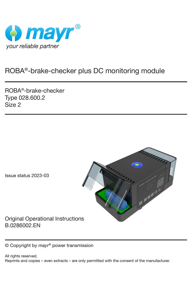
Mayr ROBA 028.600.2 Quick start guide

Mayr

Mayr ROBA 028.600.2 Quick start guide

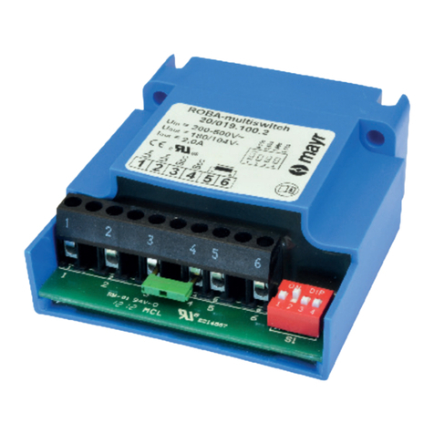
Mayr ROBA-multiswitch 019.00.2 Series User manual

Mayr

Mayr ROBA-multiswitch 019.00.2 Series User manual

Mayr ROBA-brake-checker plus AC Quick start guide

Mayr

Mayr ROBA-brake-checker plus AC Quick start guide

Popular Control Unit manuals by other brands

TLV L Series instruction manual

TLV

TLV L Series instruction manual

Yanmar TVK-YL610P installation instructions

Yanmar

Yanmar TVK-YL610P installation instructions

NHP ATYSC CIPACB Series installation manual

NHP

NHP ATYSC CIPACB Series installation manual

WAGO 750-632 manual

WAGO

WAGO 750-632 manual

Satronic 0620720 manual

Satronic

Satronic 0620720 manual

Belden GRASS VALLEY MDX-3901 Guide to installation and operation

Belden

Belden GRASS VALLEY MDX-3901 Guide to installation and operation

Yamaha ACD1 owner's manual

Yamaha

Yamaha ACD1 owner's manual

APART E-VOL20 manual

APART

APART E-VOL20 manual

Bandini Industrie GiBiDi BA230 Instructions for installations

Bandini Industrie

Bandini Industrie GiBiDi BA230 Instructions for installations

Digitax 4GMCU Technical manual

Digitax

Digitax 4GMCU Technical manual

Salus KL04RF Installation and wiring guide

Salus

Salus KL04RF Installation and wiring guide

Ebyte E220-400M30S user manual

Ebyte

Ebyte E220-400M30S user manual

Sanyo Denki F Series instruction manual

Sanyo Denki

Sanyo Denki F Series instruction manual

tau D729MA installation guide

tau

tau D729MA installation guide

Spectech VARI-DRIVE KBWM-120 Installation and operating instructions

Spectech

Spectech VARI-DRIVE KBWM-120 Installation and operating instructions

VAT 264 Series Installation, operating,  & maintenance instructions

VAT

VAT 264 Series Installation, operating, & maintenance instructions

Kemo Electronic M171 manual

Kemo Electronic

Kemo Electronic M171 manual

Pfeiffer Vacuum EVA 016 H operating manual

Pfeiffer Vacuum

Pfeiffer Vacuum EVA 016 H operating manual

manuals.online logo
manuals.online logoBrands
  • About & Mission
  • Contact us
  • Privacy Policy
  • Terms and Conditions

Copyright 2025 Manuals.Online. All Rights Reserved.