MAYTONI TRX001-111B User manual

www.maytoni.demaytoni technical
SINGLEPHASE TRACK
SYSTEM
UNITY
www.maytoni.demaytoni technical
SINGLEPHASE LIGHTING
TRACK SYSTEM
The track is the basis for the construction of track lighting systems and is intended
for installation and supply of power lines to track lighting fixtures in AC networks
with a rated voltage of 230V and a frequency of 50Hz. The track may be used
indoors only in the absence of an aggressive environment and foreign aerosol
particles at a temperature from 0 °C to +50 °C and a max. relative humidity of
80%. Options may be installed on walls and ceilings, in grooves, in specially
prepared recesses made of normally flammable materials. There is also another
installation option using rope suspensions. The track is supplied in segments with
a length of 1 and 2 meters. It is allowed to cut off segments and build structures of
various shapes using connectors.
Article
Supply voltage and frequency ~230V 50Hz
Electrical shock protection class III
Mounting method Surface-mounted/suspended/built-in
Ingress Protection Code IP20
Climatic version
Operating temperature 0° - +50°
Material Aluminium
Colour Black
Track length 1m 2m
TECHNICAL DATA
Boreal climate()
Rated current
TRX00B
TRX00W
TRX00B
TRX00W
TRX00B
TRX00W
TRX00B
TRX00W
0A

www.maytoni.demaytoni technical
1
7
2
8
3
9
654
9
5
2
10
6
7
4
8
1
3
track
TRX001 -111B
TRX001 -111W
TRX001 -112B
TRX001 -112W
power input
TRA00BB
TRA00BW
straight connector
TRA00CB
TRA00CW
L-shaped
connector
TRA00CLB
TRA00CLW
flexible connector
TRA00CFB
TRA00CFW
plug
TRA00ECB
TRA00ECW
T-shaped connector
TRA00CTB
TRA00CTW
X-shaped connector
TRA00CXB
TRA00CXW
cable suspension
TRA00CWB
TRA00CWW
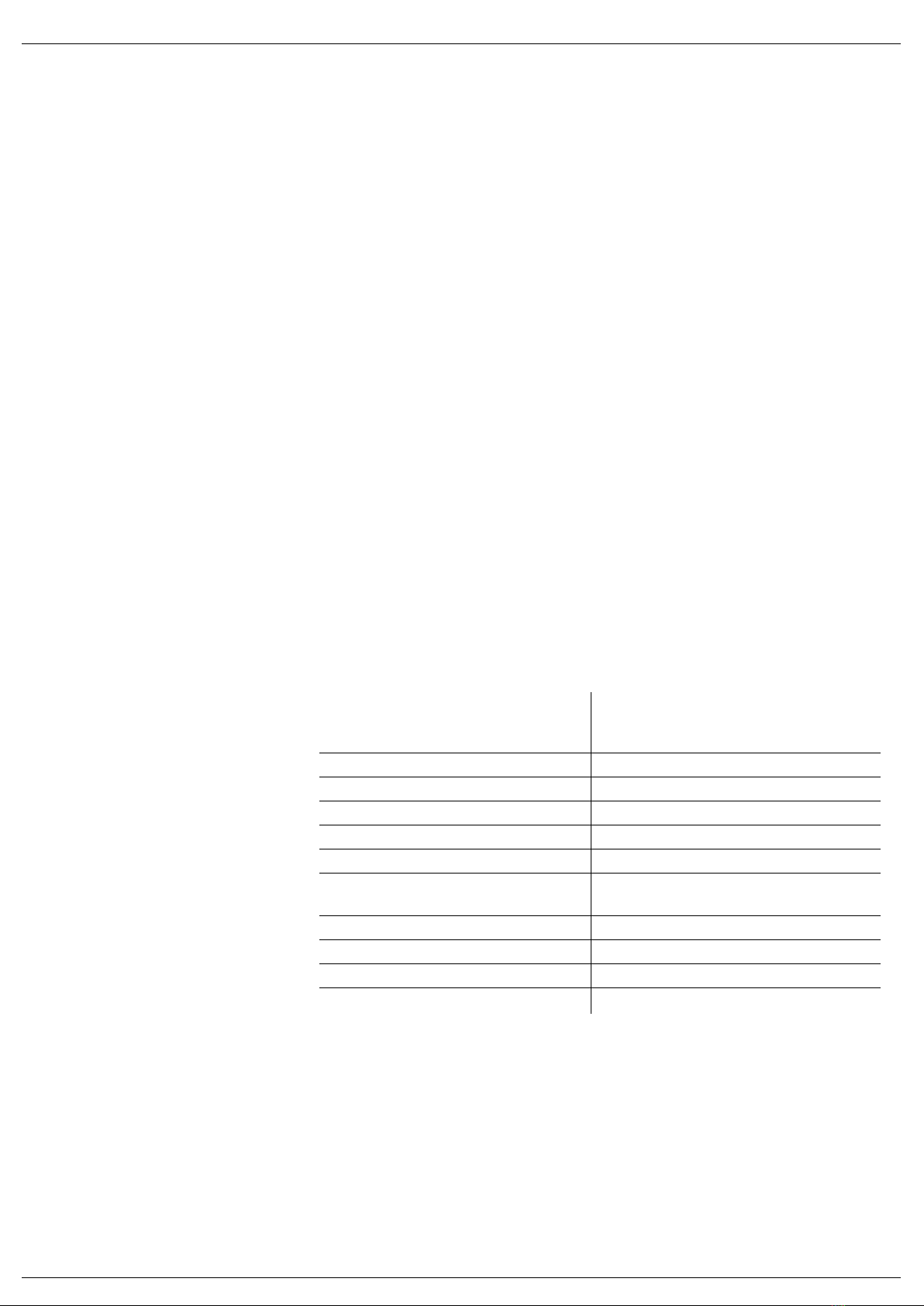
SINGLEPHASE UNITY
TRACK SYSTEM
DIAGRAM OF SURFACE AND SUSPENDED MOUNTING
SINGLE-PHASE TRACK SYSTEM

www.maytoni.demaytoni technical
single-phase track
20 × 33 × 1000 mm
TRX001-111B
TRX001-111W
single-phase track
20 × 33 × 2000 mm
TRX001-112B
TRX001-112W
single-phase
track/track adapter
17,5 x 100 x 100
mm
TRA010-1-BS-B
TRA010-1-BS-W
power input
TRA00BB
TRA00BW
straight
connector
TRA00CB
TRA00CW
plug
TRA00ECB
TRA00ECW
flexible
connector
TRA00CFB
TRA00CFW
Lshaped
connector
TRA00CLB
TRA00CLW
Tshaped
connector
TRA00CTB
TRA00CTW
Xshaped
connector
TRA00CXB
TRA00CXW
cable suspension
TRA00CWB
TRA00CWW
connectors for pendant mounting
of lamps in a track
TRA011-1-A-B
TRA011-1-A-W
ELEMENTS OF A SINGLEPHASE TRACK
SYSTEM UNITY FOR SURFACE AND
SUSPENDED MOUNTING
SURFACE AND SUSPENDED MOUNTING SINGLE-PHASE TRACK
ACCESSORIES FOR SURFACE AND SUSPENDED MOUNTING SINGLE-PHASE TRACK
www.maytoni.demaytoni technical
T-shaped connector
R2CT-11
R2T-11W
track
TRX004 -111B
TRX004 -111W
TRX004 -112B
TRX004 -112W
spring holder
TRA002HR-11B
1 2 3 4 5 6
7 8
5
1
3
6
4
2
8
7
SINGLEPHASE UNITY
TRACK SYSTEM
DIAGRAM OF BUILT-IN
SINGLE-PHASE TRACK
power input
TRA00BB
TRA00BW
straight connector
TRA00CB
TRA00CW
L-shaped connector
TRA00CLB
TRA00CLW
plug
TRA00ECB
TRA00ECW
X-shaped
connector
TRA00CXB
TRA00CXW

www.maytoni.demaytoni technical
single-phase track
20 × 60 × 1000 mm
TRX004-111B
TRX004-111W
single-phase track
20 × 60 × 2000 mm
TRX004-112B
TRX004-112W
SINGLEPHASE UNITY
TRACK SYSTEM
BUILTIN MOUNTING SINGLEPHASE TRACK
ACCESSORIES FOR BUILT-IN MOUNTING SINGLE-PHASE TRACK
X-shaped connector
20 × 130 × 130 mm
R002CX-11
R002X-11W
spring holder
37 45 32 mm
TRA002HR-11B
sealing plug
20 × 60 × 37 mm
TRA002EC-11B
TRA002EC-11W
power input
TRA00BB
TRA00BW
straight
connector
TRA00CB
TRA00CW
Lshaped connector
TRA00CLB
TRA00CLW
Tshaped connector
RCT
RTW
connectors for suspended mounting
of lamps in a track
TRA0AB
TRA0AW

www.maytoni.demaytoni technical
GENERAL RECOMMENDATIONS AND
PRECAUTIONS
All installation and mounting services must be rendered by persons having
the appropriate permits and qualifications. Please contact a qualified
electrician, where necessary.
All installation and dismantling work should be performed in a powered
down state only.
The track may not be used without a protective grounding wire.
When building a tracking system, make sure not to exceed the total load of
electric consumers of 10A (total power of lighting fixtures is not more than
2300 W).
Do not install the track at a height below 2.5 meters, or in places where
people may accidentally touch the track.
Do not use the product with a damaged housing and damaged insulation of
the supply cable.
The product is intended for indoor use only.
Do not use the product in rooms with high humidity and with a high content
of dust or aerosol particles in the air.
Make sure to install lighting fixtures on a 1m track segment with a spacing
of no more than 25 cm.
Use a soft, dry cloth to clean the product with the power switched off. Do
not use chemically aggressive cleaning agents.
!
www.maytoni.demaytoni technical
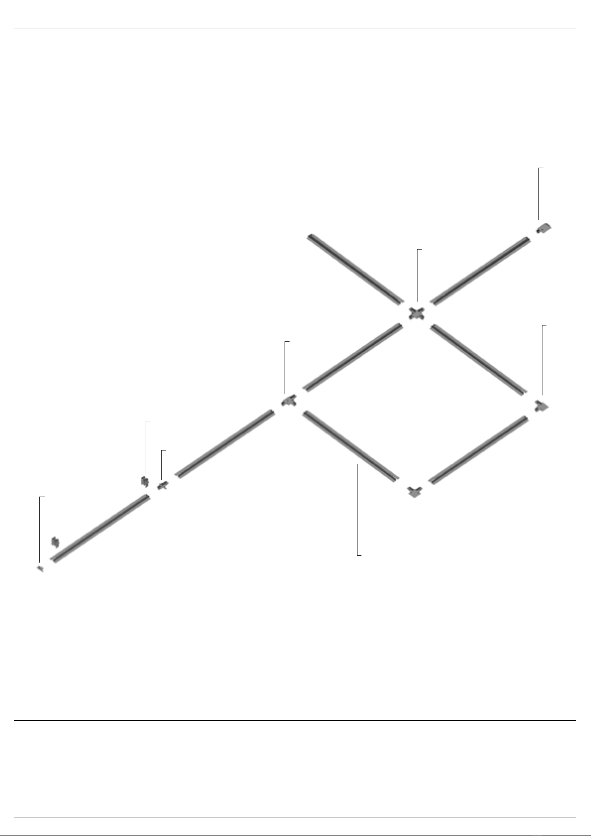
GENERAL RECOMMENDATIONS AND
PRECAUTIONS
PERMISSIBLE LOADS AND POSITIONS
OF FASTENING ELEMENTS
The max. distance between suspension mounts is
1 m. The recommended distance between lamps
is 25 cm. The maximum permissible load on the
surface-mounted track installed using suspension
fasteners is 10 kg per 1 meter.
The max. distance between fasteners to
the surface is 80 cm. The recommended
distance between lamps is 25 cm.
The maximum permissible load on the
surface-mounted track installed on
a rough surface is 10 kg per 1 meter.
In order to create closed continuous
contours, please use TRA001CF-11
and arrange power input through them.
The distance between the holders is
selected based on the weight of installed
lamps. The lamp weight at 1 meter ≤ 5 kg
- the distance between holders is 50 cm.
The lamp weight at 1 meter ≤ 10 kg — the
distance between holders is 30 cm. The
recommended distance between lamps
is 25 cm. The max. permissible load on
the built-in track installed using holders is
10 kg per 1 meter.
SURFACE MOUNTING
BUILT-IN INSTALLATION
USING SPRING HOLDERS
kg
cm
cm cm
cm
cm
cm
kg
kg kg
kg
SUSPENDED MOUNTING

www.maytoni.demaytoni technical
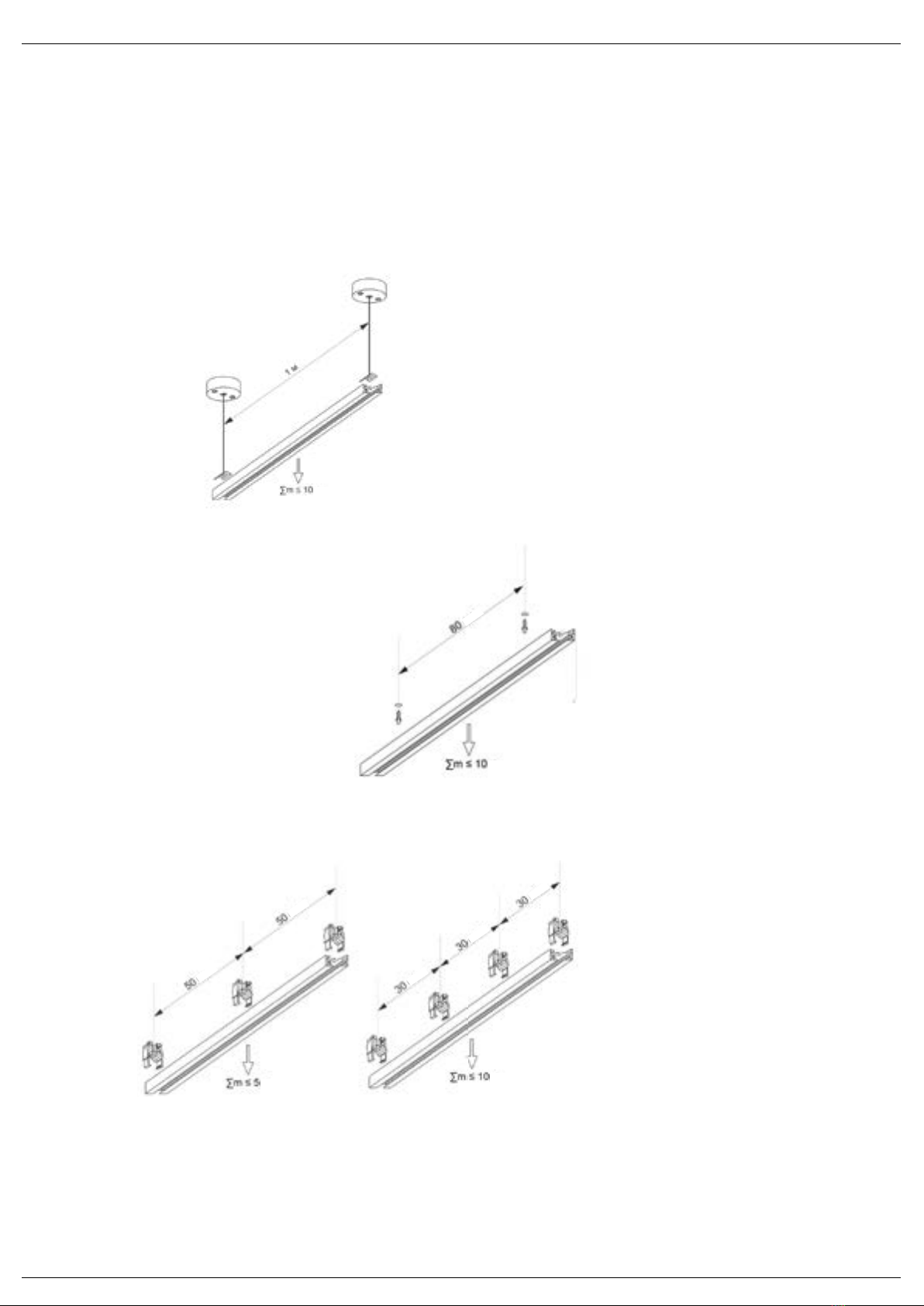
CONNECTION OF A SINGLEPHASE
TRACK TO POWER SUPPLY
1. Before connecting the track, make sure to de-energize the supply cable. Remove the track from the
packaging, make sure that the housing and current-carrying parts are not damaged. Disconnect the power
lead-in from the track.
2. Remove the screw on the front side of the power lead-in using a screwdriver and remove the plastic cover.
3. Lay the three-core cable to the track installation site. Connect the protective ground wire to the yellow-green
wire on the power lead-in housing. Pull the phase and neutral wires through the hole in the back side of the
power lead-in.
4. Fasten the phase and neutral conductors on the contact plates using clamping screws.
5. Close the power lead-in by taking steps stated in clause 2 in a reverse order.
6. Insert the connected power lead-in into the track. Install the track in the most relevant way.
A single-phase track of all types is connected to a 230V 50Hz AC mains through a power lead-in. The relevant
end power lead-in is included with delivery of each track segment.
1
4
2
5
3
6

www.maytoni.demaytoni technical
INSTALLATION PLAN FOR SURFACE
MOUNTED SINGLEPHASE TRACK
CAUTION
Do not tighten the screws at high screwdriver speed and do not tighten until it stops to avoid deformation of the track.
The rules for installation of fasteners are given in the section "General recommendations and precautions".
34.00
34.00
19.50
TRACK INSTALLED ON
A CONCRETE CEILING
TRACK INSTALLED ON A GYPSUM
BOARD CEILING
19.50
The surface-mounted single-phase track may be installed on any hard surface made
of normally flammable materials. During the installation, carefully prepare and correctly
mark the mounting surface to avoid bending moments that may cause deformation of
the track.
When installing the surface-mounted track, select the appropriate fasteners based on
the material of the mounting surface.

www.maytoni.demaytoni technical
INSTALLATION PLAN FOR SURFACE
MOUNTED SINGLEPHASE TRACK IN
SUSPENDED WAY
The surface-mounted single-phase track can be installed in a suspended way
on a concrete ceiling and plasterboard suspended ceiling as well as other types
of ceiling provided that necessary embedded parts are available and sufficient
firmness of construction materials is secured.
When suspending the surface-mounted track, select fasteners that suit to the
ceiling material.
For the suspended mounting of the track, use special suspension kits
TRA001CW-11B/TRA001CW-11W, consisting of a rope with an end locking element
to adjust its length, the bracket and ceiling bowl.
1. Unpack the track and visually check for possible defects.
2. Mark the installation locations and prepare the mounting brackets for their
subsequent fixation on the track.
3. Fix the ceiling bowl on the ceiling.
4. Insert the rope into the collet on the mounting bracket and adjust the length.
5. Cut off the unnecessary part of the rope.
6. Fix the bracket on the track with the screws located on top.
7. Use the carpenter level to check the levelness, if necessary, adjust the length
of the ropes.
CAUTION
When mounting several connected track segments in a suspended way, place them strictly horizontally, avoid skewness and
uneven tension of ropes.
prepare the mounting surface
mark and drill the holes
insert the dowels into the holes
attach the ceiling bowl
fix it with screws
adjust the installation height
using the collet fixtures
push the plate into the groove on
the back side of the track
fix the plate with screws
INSTALLATION OF SUSPENDED
MOUNTED SINGLE-PHASE TRACK
USING A SUSPENSION MOUNT
www.maytoni.demaytoni technical
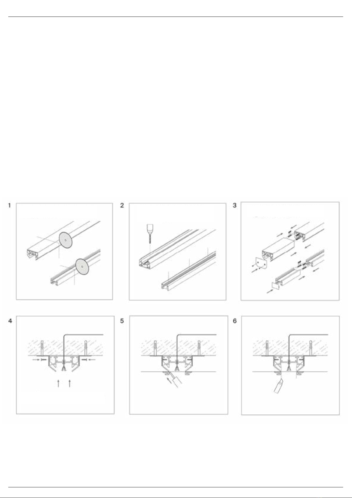
INSTALLATION DIAGRAM FOR SURFACE
MOUNTED SINGLEPHASE TRACK WITH A
PROFILE FOR STRETCHED CEILING
In order to implement this option, you need to purchase the profile not in the assortment,
sold separately in addition to the surface-mounted track and perform installation as
follows:
1. Cut the profile and track in the required length.
2. Drill the mounting holes and cable entry holes.
3. Assemble all parts of the profile and track if required, and insert the plugs.
4. Fix the profile to the surface using the mounting angles.
5. Stretch the ceiling cloth and glue the edges of the harpoons along the entire profile
length.
6. Leave a slot between the harpoons.
INSTALLATION OF SURFACE-
MOUNTED SINGLE-PHASE TRACK
WITH A PROFILE FOR STRETCHED
CEILING
CAUTION
Installation of track with this profile is only possible using PVC cloths for a stretched ceiling.
maytoni technical www.maytoni.ru
СХЕМА УСТАНОВКИ НАКЛАДНОГО
ОДНОФАЗНОГО ШИНОПРОВОДА
С ПРОФИЛЕМ ДЛЯ НАТЯЖНОГО
ПОТОЛКА
Для осуществления данного варианта в дополнение к накладному шинопроводу
приобретается профиль TRA004MP-21S и монтаж проводится следующим
образом:
1. Нарежьте профиль и шинопровод необходимой длины.
2. Просверлите монтажные отверстия и отверстия для ввода кабеля.
3. Соберите все части профиля и шинопровода если это требуется,
4. установите заглушки.
5. Заркепитепрофиль на поверхности спомощью монтажныхуголков.
6. Натяните полотнопотолкаи проклейте краягарпунов по всей длине
7. профиля.
МОНТАЖ НАКЛАДНОГО
ОДНОФАЗНОГО ШИНОПРОВОДА
С ИСПОЛЬЗОВАНИЕМ ПРОФИЛЯ
ДЛЯ НАТЯЖНОГО ПОТОЛКА
ВНИМАНИЕ!
Монтаж шинопровода с использованием данного профиля возможно только с применением ПВХ полотен
для натяжного потолка.

www.maytoni.demaytoni technical
7. Put the harpoons into the profile grooves and glue the end faces.
8. Install the track and fix it inside the profile.
9. The track is ready for operation and installation of lamps on it.
maytoni technical www.maytoni.ru
СХЕМА УСТАНОВКИ НАКЛАДНОГО
ОДНОФАЗНОГО ШИНОПРОВОДА
С ПРОФИЛЕМ ДЛЯ НАТЯЖНОГО
ПОТОЛКА
МОНТАЖ НАКЛАДНОГО
ОДНОФАЗНОГО ШИНОПРОВОДА
С ИСПОЛЬЗОВАНИЕМ ПРОФИЛЯ
ДЛЯ НАТЯЖНОГО ПОТОЛКА
8. Сделайте прорезь между гарпунами.
9. Заправьте гарпуны в пазы профиля и проклейте торцы.
10. Установите шинопровод и закрепите его в профиле.
11. Шинопровод готов к эксплуатации и монтажу светильников на нем.
INSTALLATION DIAGRAM FOR SURFACE
MOUNTED SINGLEPHASE TRACK WITH A
PROFILE FOR STRETCHED CEILING
INSTALLATION OF SURFACE-
MOUNTED SINGLE-PHASE TRACK
WITH A PROFILE FOR STRETCHED
CEILING

www.maytoni.demaytoni technical
CAUTION
If you wish to install a built-in track in the gypsum board ceiling, use an additional accessory — holder TRA002HR-11B. The rules
for installation of fasteners are given in the section "General recommendations and precautions".
The built-in single-phase track may be installed in a groove or a specially prepared
recess and in a suspended ceiling made of gypsum boards.
When installing a built-in track, select fasteners with due regard for the ceiling
design.
TRACK INSTALLED IN A GROOVE OR
RECESS
TRUCK INSTALLED IN A GYPSUM
BOARD CEILING
INSTALLATION DIAGRAM FOR BUILTIN
SINGLEPHASE TRACK
60.00
60.00
34.00
40.00
34.00
40.00
1.00
19.00
19.00
www.maytoni.demaytoni technical
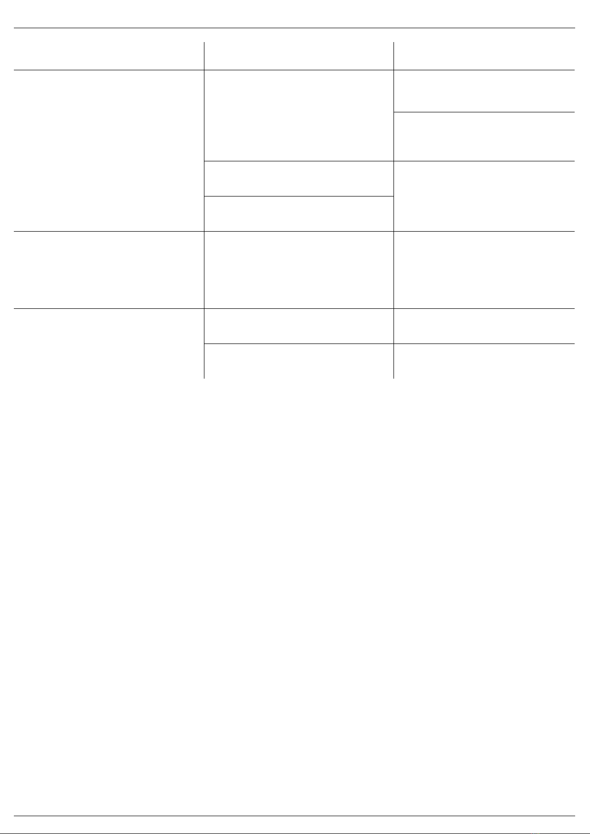
Fault description Cause Remedy
The lighting fixture does not operate Loose connection of current-carrying
parts
Install the lighting fixture on the track
until full contact between the adapter
and current-carrying wires is reached
Check the contacts of the lead-in
cable, connection of the lead-in
contacts to the track, and other
connections.
Contact the seller
to replace it under a warranty
Contact the seller for a warranty
replacement
Malfunction of lighting fixture
The lighting fixture flashes or glows
dimly in switched-off state
A switch with illuminated keys is
installed, or a motion (light) sensor is
used to control the lighting circuit
Replace the switch with a model
without backlit keys, or with auxiliary
incorporated resistor. Use the motion
(light) sensor with a relay output only
Unstable glowing, flickering, unusual
sound
Brightness control (dimmer switch) is
installed in the power supply circuit
Remove the brightness control from
the circuit, replace it with a switch
Defective power supply source / lamp
driver
Contact the seller for a warranty
maintenance or replacement
Store the product indoors, in the original packaging in a place protected from
aggressive environment. Store at a temperature in the range from -20 °C to +70°
C and relative humidity not exceeding 95%. Direct exposure to moisture is not
allowed.
The product is shipped in a package which is suitable for transportation by sea,
rail, road and air.
STORAGE
TRANSPORTATION
DISPOSAL Do not dispose the product with the regular household waste!
Products must be disposed according to the directive on electrical and
electronic devices at local collection points for such
devices!

www.maytoni.demaytoni technical
WARRANTY
Maytoni GmbH, Feldstiege 98, Münster, Germany, 48161
Maytoni GmbH, Feldstiege 98, Münster, Germany, 48161
Developed in Germany.
Made in China.
Shelf life is not limited.
MANUFACTURER
IMPORTER
The warranty is granted for a period of 24 months from the date of sale which is
determined on the basis of documents serving as proof of purchase.
This warranty covers defects in workmanship provided that all rules of operation,
transportation and storage given in this manual are complied with.
The warranty is not valid in following cases: if the product has been used for
the purposes other than it is intended for; the malfunction occurred after the
handover of goods to the consumer and was caused by improper or negligent
handling, failure to observe the requirements set forth in these instructions. And
in force majeure circumstances as well, in particular in the following events: fire,
flood, high-voltage discharges, and other natural disasters, accidents and wilful
acts of third parties that caused the product to malfunction.

This manual suits for next models
7
Table of contents


