4
REQUIRED TOOLS
☆Screwdriver (Flathead) ☆Screwdriver (Phillips) ☆Socket wrench ☆Torque wrench ☆Nipper
☆Pliers ☆Fastener remover ☆Punch ☆Drill ( 2 mm) ☆Hole saw ( 20 mm) ☆Round file
☆Tweezers ☆Protective tape ☆Electrical vinyl tape ☆Soft clean cloth ☆Mat
☆IPA (Isopropyl alcohol)
WARNING
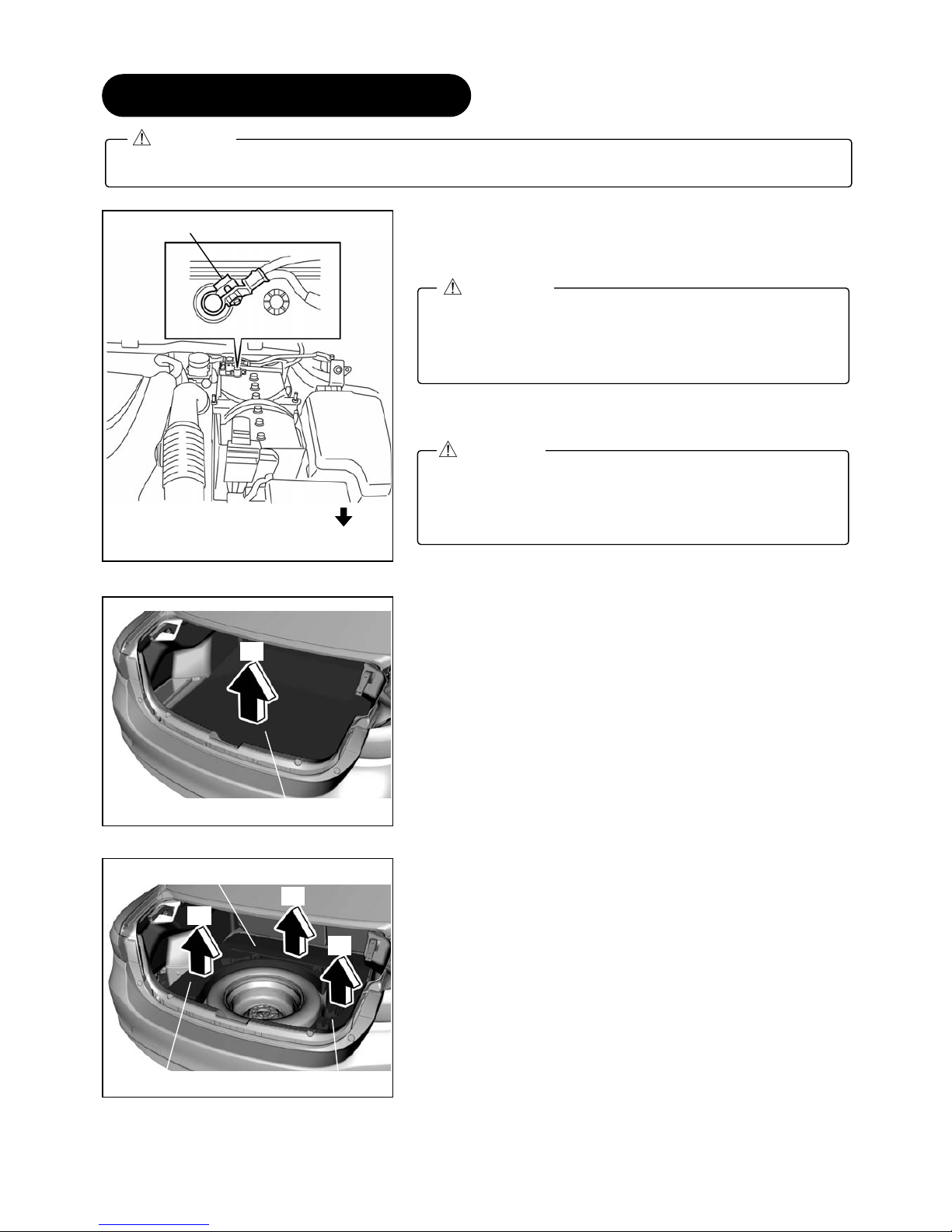
When the negative battery
cable is connected during
operation, it may cause
electric shock or other
personal injuries. Disconnect
the negative battery cable
before removal/installation.
When connecting/dis-
connecting connectors, grasp
the connectors, not the wires.
Otherwise a short, and an
accident from poor contact or
fire may occur.
Do not pull the harness with
excessive force. Doing so
can cause a breakage or a
short-related accident, as
well as an electrical short or
fire.
Secure the harness with the
band (part included) so it
doesn’t dangle. If not, it may
cause a short, accident, or
fire.
CAUTION
Using improper tools may
cause damage and/or broken
parts. Use the correct tool for
the job.
Wrap protective tape around
screwdrivers and fastener
remover tools to prevent
scratching the vehicle.
Excessive length of tie wrap
may interfere with other parts
and cause damage.
Cut unnecessary part up to
about 5 mm {0.19 in} from
the fixed point.
Put the removed parts and
the parts in the kit on the
protective sheet to prevent
scratches.
2.BEFORE INSTALLATION
•When the negative battery cable is removed, the clock, radio, trip meters and other memories will be erased.
Before performing work, record the content of the memory.
•Refer to the Workshop Manual for removal and installation of vehicle parts.
Not following the procedures for removal/installation in the Workshop Manual could result in an accident or
vehicle malfunction.
Note
•When removing/installing the parts, park the vehicle on level ground and apply the side brake securely. Be
sure to turn the ignition switch off, otherwise the vehicle can move, causing personal injury or vehicle
damage.
WARNING