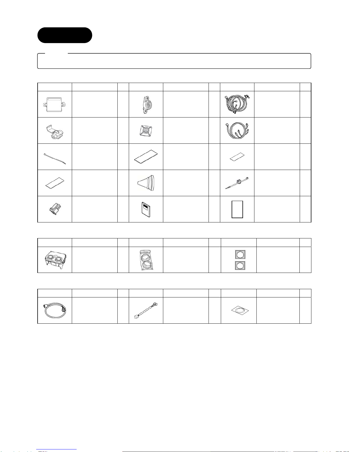
Mazda C860 V7 281A User manual

1
GENUINE PARKING SENSORS (Rear)
INSTALLATION INSTRUCTIONS
Thank you for purchasing a genuine Mazda accessory.
Before removal and installation, be sure to thoroughly read these instructions.
Please read the contents of this booklet in order to properly install and use the parking sensors
(Rear). Your safety depends on it.
Keep these instructions with your vehicle records for future reference.
There are several WARNING and CAUTION sections in this booklet concerning safety when
installing or removing the parking sensors (Rear). Always read and follow them in order to prevent
injuries, accidents, and possible damage to the vehicle.
WARNING: Indicates a situation in which serious injury or death could result if the warning
is ignored.
CAUTION: Indicates a situation in which bodily injury or damage to the vehicle could result if the
caution is ignored.
For areas indicating the tightening torque in this instruction manual, tighten to the specified torque using
a torque wrench.
Do not modify the parking sensors (Rear).
Do not install the parking sensors (Rear) remove in any way other than described in the following
instructions.
If in any doubt, please ask your Mazda dealer to install the accessory in order to prevent errors in
installation.
If you have any questions about the use of the accessory, ask your Mazda dealer for proper advice
before using it.
Mazda and its suppliers are not responsible for injuries, accidents, and damage to persons and property
that arise from the failure of the dealer or installer to follow these instructions.
To ensure safety and reliability of the work, installation, removal and disposal work must be carried out
by an Authorized Mazda Dealership.
Be careful not to lose removed parts, and be sure that they are kept free from scratches, grease or
other dirt.
PART NAME: Parking Sensors (Rear)
VEHICLE: MAZDA CX-5
PART NUMBER: KB7W V7 290A (Parking Sensors, Main Kit)
C860 V7 281A (Parking Sensors, Sensor Kit)
KD33 V7 282
(Optional ON-OFF switch)
To the dealer
Please turn over these instructions to the customer after installation.
To the customer
Keep these instructions after installation. The instructions may be necessary
for installing other optional parts or removal of this accessory.
Should the vehicle or this accessory be resold, always leave these instructions
with vehicle for the next owner.
NOTE
06DE4313B
WARNING

2
1. INSTALLATION VIEW
Back sensor
Grommet
Buzzer
Electro tap
Ground wire Rear sensor harness
Control unit
Main harness
Rear sensor
【Optional ON-OFF switch installed】
Optional ON-OFF switch
Trunk side trim (LH)
Rear sensor
Back-up sensor ON-OFF
switch (Label)

3
KB7W V7 290 (Parking Sensors, Main kit)
Part Part name Qty. Part Part name Qty. Part Part name Qty.
Control unit 1
Buzzer 1
Main harness 1
Electro tap 1 Mount base 9
Sensor harness 1
Tie wrap 30
Double-sided
adhesive tape
(Control unit)
1
Double-sided
adhesive tape
(Buzzer)
1
Cushioning tape 2
Grommet 1
Crump tie wrap 1
Female contact
housing 1
Installation
instructions 1
User manual 1
C860-V7-281A (Parking Sensors, Sensor kit : needed x2 sets for a vehicle)
Part Part name Qty. Part Part name Qty. Part Part name Qty.
Sensor 2
rubber 2
Sensor spacer 2
KD33-V7-282 (Optional ON-OFF switch)
Part Part name Qty. Part Part name Qty. Part Part name Qty.
Optional
ON-OFF switch 1
Harness
(With electro taps)1
Back-up sensor
ON-OFF switch
(Label)
1
2. PARTS
Verify that the kit includes all the following parts and that the parts are not dirty, scratched, or damaged.
Note

4
REQUIRED TOOLS
☆Screwdriver (Flathead) ☆Screwdriver (Phillips) ☆Socket wrench
☆Box-end wrench/Combination wrench ☆Torque wrench ☆Nipper
☆Pliers ☆Hole saw (20mm) ☆Drill (1.5mm,3mm)
☆Punch ☆Pincers ☆Remover tool
☆Flathead screwdriver wrapped with protective tape ☆Fastener remover wrapped with protective tape ☆Flat, round file
☆Round file ☆Deburring Tool ☆Masking tape
☆Soft clean cloth ☆Electrical vinyl tape ☆Mat
☆IPA (Isopropyl alcohol)
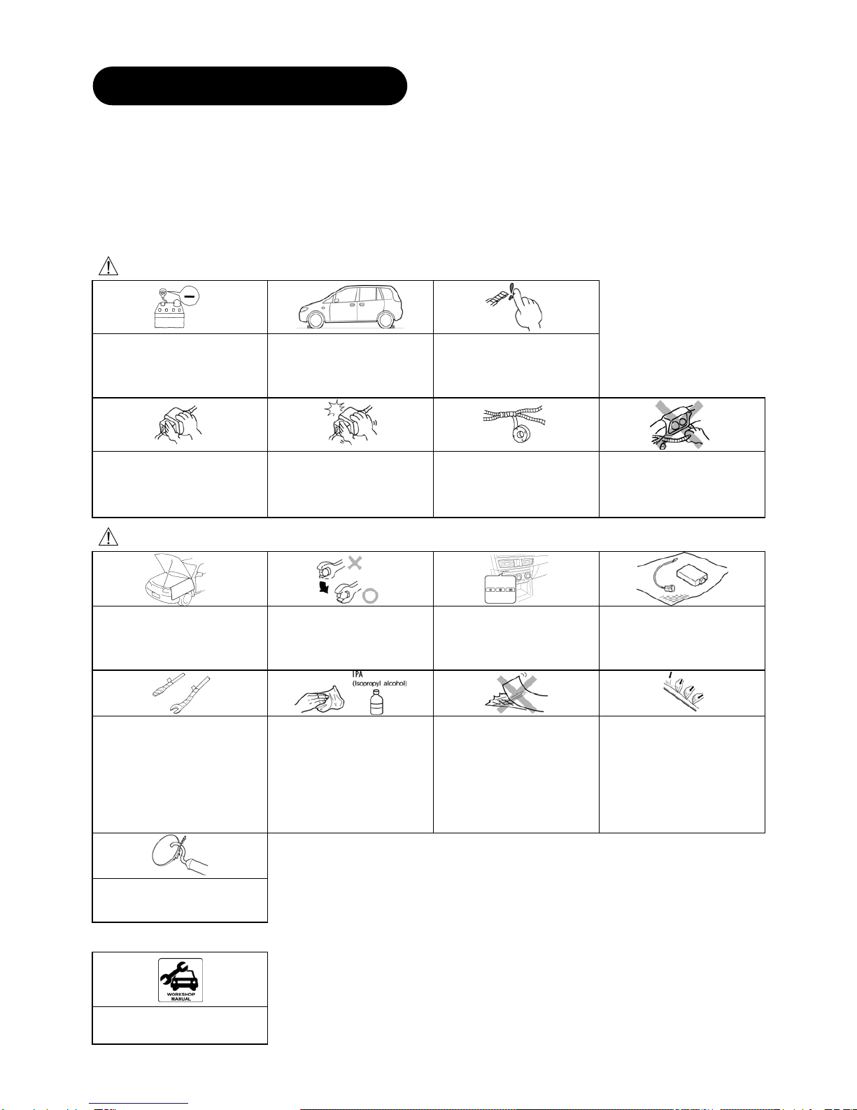
WARNING
If the negative battery is
connected while performing the
work, it may cause electrocution
or other personal injuries.
Disconnect the negative cable
before /installation.
Before performing any work,
park the vehicle on level ground,
apply the parking brake
securely, and then block the
wheels.
Be careful when handling drills
and other sharp objects.
If not handled properly, it could
result in serious injury.
When connecting/disconnecting
connectors, grasp the connectors,
not the wires. Otherwise, a fire or
other accident could occur due to
a short circuit or poor contact.
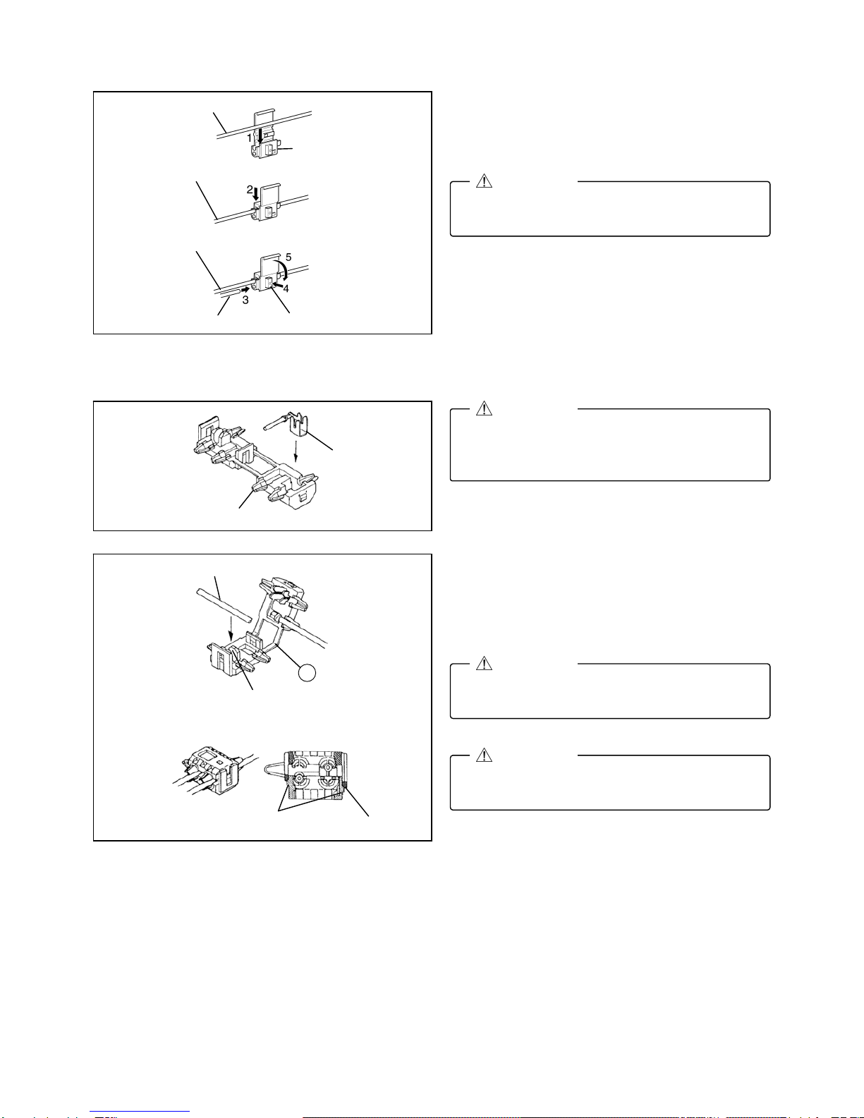
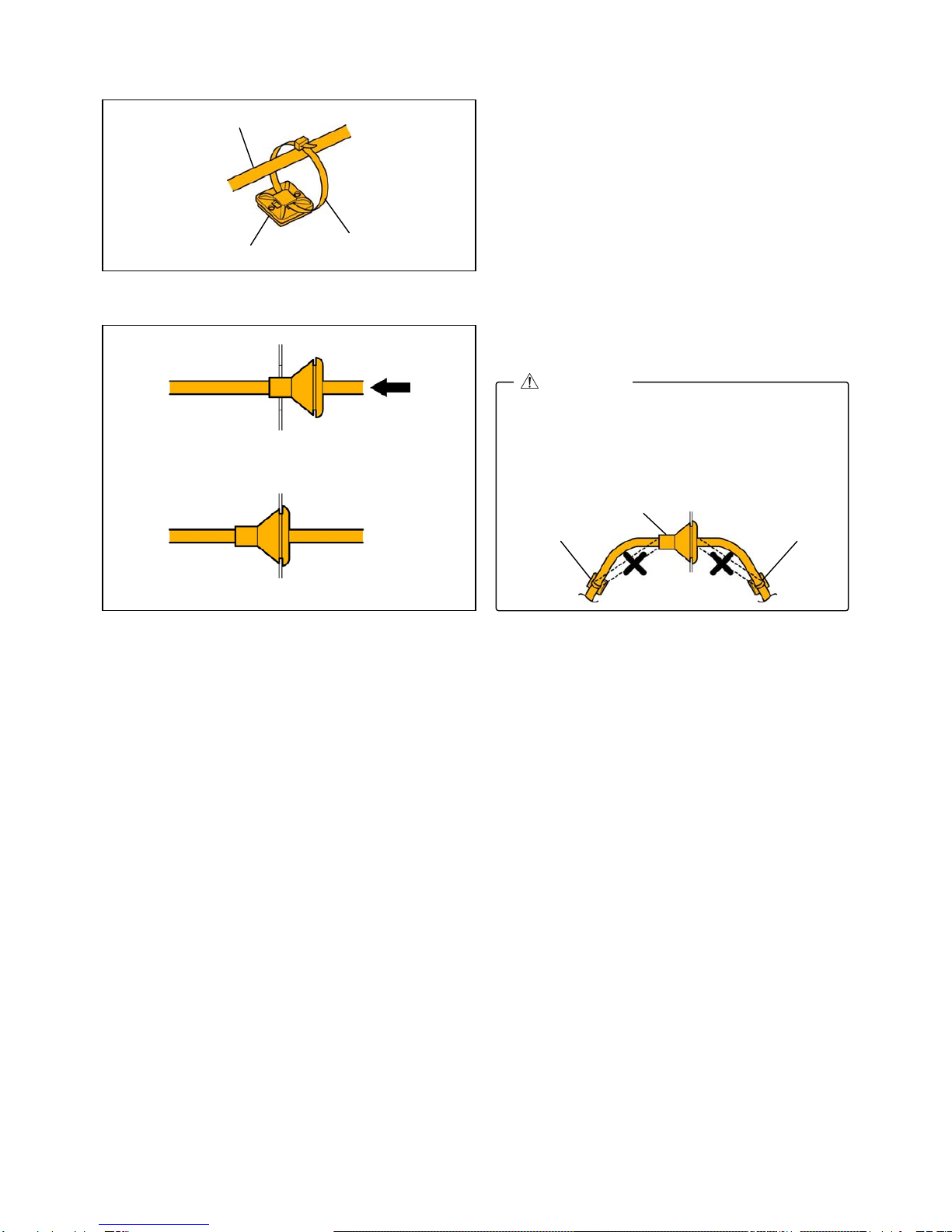
Make sure the connector is
securely pressed in until a click
sound is heard.
Otherwise, a fire or other
accident may occur due to an
open circuit or poor contact.
Secure the wiring harness with
the tape (part included) so that
they are not left dangling.
Otherwise, a fire or other
accident may occur due to a
short circuit.
Do not pull a wiring harness with
excessive force. Doing so can
cause breakage which could
result in a short circuit or a fire.
CAUTION
Be sure to cover the vehicle body
with protectors or mats to prevent
stains, scratches and damage
when removing/installing the
vehicle parts.
Using improper tools may
damage parts. Use the correct
tool for the job.
When the negative battery cable
is removed, the initial value or
memory for the power windows,
clock, i-stop, steering angle
sensor reference point will be
cleared. Perform re-initialization.
Put the removed parts and the
kit accessory parts on a
protective sheet to prevent
scratches.
Wrap protective tape around
screwdrivers and fastener
remover tools to prevent
scratching the vehicle.
If there is dust, dirt or grease on
the adhesion surface, the
adhesive strength of the
double-sided adhesive tape will
be weakened. Wash and
degrease the surface of the
adhesion area before applying
the double-sided adhesive tape.
Be sure to wash interior and
exterior parts using IPA
(
iso
p
ro
py
l alcohol
)
.
If tape or a mount base is
removed and then re-adhered,
the adhesive strength will be
weakened. Before adhering,
accurately determine the
adhesion position.
To assure sufficient
adhesiveness of the
double-sided adhesive tape,
press the adhesive surface of
the tape to the adhesion surface
evenly.
In particular, press sufficiently at
the ends of the double-sided
adhesive tape where the
adhesion surface is curved.
Make sure to remove burrs from
the surface so that the bumper
surface is smooth.
Advice
Refer to the Workshop Manual
for removal and installation of
vehicle parts.
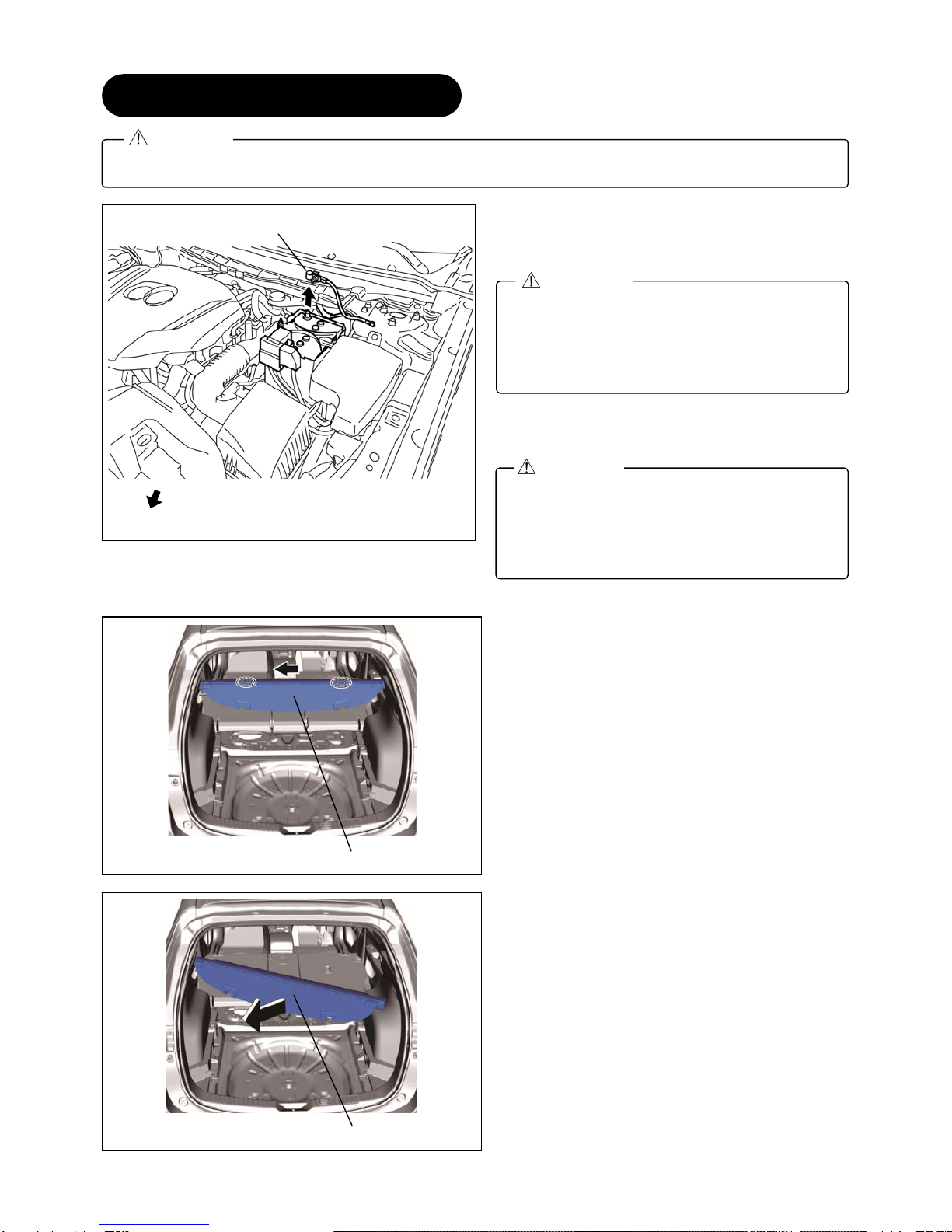
3. BEFORE INSTALLATION

5
■ Branch connection procedure using electro tap
1. Insert the harness and vehicle wiring harness into
the electro tap.
2. Fold the electro tap as shown in the figure and lock
it.
3. Insert the harness to the end of the electro tap.
4. Firmly press the electro tap terminal using pliers.
5. Fold the electro tap in the direction of the arrow
shown in the figure and lock it.
6. Soundproof using urethane tape.
■ Branch connection procedure using electro-tap (Optional ON-OFF switch installed)
1. Put the harness to be branch-connected into the
guide groove.
2. Fold back the electro-tap from the A part as shown
in the figure.
3. Lock the electro-tap temporarily.
4. Firmly press the electro tap terminal using pliers.
Firmly engage the lock part until a click sound
is heard.
CAUTION
The temporary lock is provided on only one
side. Stop short of lockin
g
the final locks.
CAUTION
Pinch the electro-tap until a clicking sound is
heard from the final locks on the both sides.
CAUTION
Electro tap
Harness
Firmly press
using pliers
Vehicle wiring harness
Lock
Lock
Vehicle wiring harness
Terminal
Vehicle wiring harness
The terminal is embedded in the insulator. If it
is not, insert the terminal as shown in the figure
and press it in until it is securely fixed.
CAUTION
Terminal
Insulator
Guide groove
Harness
A
Temporary lock
Final lock

6
■ Securing harness
1. When the wiring harness is secured using a mount
base, passing a tie wrap through the mount base
and temporarily tightening the wiring harness as
shown in the figure will make the operation easier.
■ Securing grommet
1. When inserting the grommet, firmly press in the
entire circumference by hand.
Completely encapsulate with no eversion on
the grommet. Otherwise, water may penetrate
the cabin causing rust or a malfunction.
When securing the tie wrap, be careful not to
deform the grommet or separate it at the ends.
Grommet
Tie wrap Tie wrap
CAUTION
Tie wrap
Mount base
Harness
Press in
Vehicle interiorVehicle exterior
Installed condition
Vehicle interiorVehicle exterior

7
4.CONNECTION DIAGRAM
Figure shows connector viewed from harness side.
Wire color indicated in figure is wiring harness color for
parking sensor kit.
GR

8
Negative battery cable disconnection
1. Set the selector lever to P range.
(AT vehicles only)
2. Disconnect the negative battery cable and wrap
tape around it to insulate.
Tightening torque : 4.0-6.0 N・m
Tonneau cover removal
1. Hold the shaded areas shown in the figure and move
the tonneau cover in the direction of the arrow.
2. Remove the tonneau cover in the direction of the
arrow shown in the figure.
5.
V
EHICLE PART REMOVAL
Be careful not to damage or lose any parts removed from the vehicle since they will be reused.
CAUTION
When removing/installing the parts, park the
vehicle on level ground and apply the side
brake securely. Be sure to turn the ignition
switch off, otherwise the vehicle can move,
causing personal injury or vehicle damage.
WARNING
If the negative battery cable is connected while
performing the work, it may cause electrocution
or other personal injuries. Disconnect the
negative battery cable before
removal/installation.
WARNING
Negative battery cable
Vehicle front
Tonneau cover
Tonneau cover

9
Trunk board removal
1. Remove the center trunk board.
2. Remove the trunk board RH and trunk board LH.
Center trunk board
Move the center trunk board in the direction of
the arrows shown in the figure, and remove the
ends of the center trunk board from the gap
between the trunk side trim and the rear seat
back.
Note
Trunk board RHTrunk board LH
End of center trunk board
Rear seat back
Trunk side trim
Rear seat back
Trunk side trim
Rear seat back
Trunk side trim Trunk side trim
Center trunk board

10
Bass-box removal
1. Remove the bolt.
2. Disconnect the connector.
3. Remove the bass box and short cord as a single
unit.
With spare tire Short cord
Without spare
ConnectorBass box
ConnectorBass box
Short cord
Bolt : 4.0—8.0 N·m
{41—81 kgf·cm, 36—70 in·lbf}
Bolt : 4.0—8.0 N·m
{41—81 kgf·cm, 36—70 in·lbf}
With spare tire
Without spare tire
Bass box
Bass box

11
Sub-trunk removal
[With spare tire]
1. Remove sub-trunks No.1 and No.2 in the direction
of the arrows shown in the figure.
[Without spare tire]
2. Remove the sub-trunk in the direction of the arrow
shown in the figure.
Trunk end trim removal
1. Partially peel back the weatherstrip.
2. Remove the fasteners.
Sub-trunk No.1 Sub-trunk No.2
Weatherstrip
Fastener
Tr
u
nk
e
n
d
t
rim
Without Bose®
With Bose®
Sub-trunk Sub-trunk

12
3. Move the trunk end trim in the order of arrows (1) and
(2) shown in the figure, remove it while detaching the
clips, pins, and the guides.
Rear scuff plate removal
1. Hold part A shown in the figure, open the rear scuff
plate in the direction of arrow (1), move it in the
direction of arrow (2), and detach tab A of the rear
scuff plate from the B-pillar lower trim.
2. Hold the shaded areas shown in the figure, move
the rear scuff plate in the direction of arrow (3),
and detach tab B of the rear scuff plate from the
B-pillar lower trim.
B-pillar lower trim
B-pillar lower trim
Rear scuff plate
Rear scuff plate
Tab A
Part A
(2)
(3)
(1)
: Tab B
Trunk end trim Trunk end trim
: Guide
: Clip : Pin
(1)
(2)

13
3. Hold the shaded areas shown in the figure, move
the rear scuff plate in the direction of arrow (1),
detach the clip from the inner panel, and pull out
the pin.
4. Hold the shaded areas shown in the figure, move
the rear scuff plate in the direction of arrow (3),
and remove it while detaching tab B of the rear
scuff plate from the trunk side trim.
5. Hold part A shown in the figure, open the rear scuff
plate in the direction of arrow (1), move it in the
direction of arrow (2), and detach tab A of the rear
scuff plate from the trunk side trim.
6. Hold the shaded areas shown in the figure, move
the rear scuff plate in the direction of arrow (3),
and remove it while detaching tab B of the rear
scuff plate from the trunk side trim.
(1)
(2)
Rear scuff plate
Inner panel
: Clip
: Pin
Rear scuff plate
(2)
Tab A
Part A
: Tab B
Trunk side trim
(1)
(3)
Trunk side trim
Rear scuff plate

14
Trunk side trim removal
1. Insert a tape-wrapped flathead screwdriver into the
position shown in the figure, move it in the direction
of arrow (1), and while detaching the hooks of the
remote handle lever, open the cover in the direction
of arrow (2).
2. Remove the screw.
3. Remove the screw.
4. Remove the fastener.
Tape-wrapped flathead screwdriver
Hook
Hook
Remote handle leve
r
Cove
r
Cove
r
Hook
(2)
Hook
Remote handle leve
r
(1)
Remote handle leve
r
Scre
w
Scre
w
Trunk side trim
Trunk side trim
Fastene
r

15
5. Remove the bolts.
6. Remove the cargo net hooks.
7. Partially peel back the weatherstrips.
8. Remove the rear seat cushion.
9. Fold the rear seat back.
10. Insert a tape-wrapped flathead screwdriver into
the position shown in the figure, move it in the
direction of the arrows, and remove the clips.
Ta
p
e-wra
pp
ed flathead screwdrive
r
: Cli
p
Trunk side trim
Bolt : 9—12 N·m {92—122 kgf·m, 80—106 ft·lbf}
Cargo net hook
Trunk side trim
Bolt
Car
g
o net hook
Bolt
Weatherstri
p
Weatherstri
p

16
11. Move the trunk side trim in the order of arrows (1),
(2), (3), and (4) shown in the figure, and remove
the clips and hooks.
12. Move the trunk side trim in the order of arrows (1),
(2), (3), and (4) shown in the figure, and remove
the clips, hooks, and the clip of the remote handle
lever.
13. Insert a hand into the back side of the trunk side
trim, press the tabs of the remote handle lever in
the direction of arrows (1) shown in the figure,
and remove the remote handle lever in the
direction of arrow (2).
Tab
Trunk side trim
Remote handle leve
r
Trunk side trim
(1)
(1)
(2)
Tab
Tab
Remote handle leve
r
: Clip of remote
handle lever
: Cli
p
: Hook
(1)
(2)
(3)
(4)
Trunk side trim
Right side only
Trunk side trim
: Cli
p
: Hook
(1)
(2)
(3)
(4)
Left side only

17
14. Set the remote handle lever aside.
15. Move the position of the rear seat back in the
direction of arrows (1) and (2) shown in the figure,
while adjusting it at a position where the trunk
side trim can be removed, move the trunk side
trim in the direction of arrow (3) shown in the
figure, and remove it in the direction of arrow (4).
16. Disconnect the rear accessory socket connector.
Remote handle leve
r
Trunk side trim
Rear seat back
(1)
(2)
(3)
(4)
Rear accessory
socket connector
Trunk side trim
Rear accessory socket
Right side only

18
Rear combination light removal
1. Insert the remover tool into the service hole at the
position shown in the figure.
2. Move the remover tool in the direction of arrow (1)
shown in the figure and pull out the service hole
cover tab from the rear combination light.
3. Remove the service hole cover.
4. Remove the screws.
Rear combination light
Vehicle frontVehicle front
Rear combination light
Tab
Service hole cove
r
Remover tool
(1)
Rear combination light
Screw
Service hole cove
r
Rear combination light
Service hole
When removing the rear combination light from
the body, it could interfere with the body and
cause scratching or damage to the body. When
removing the rear combination light from the
body, apply protective tape to the body.
CAUTION
Fogging or condensation on the inside of the
rear combination lights may occur due to a
natural phenomenon occurring as a result of a
temperature difference between the interior and
exterior of the combination lights. However, it
has no effect on the light performance because
the temperature inside the rear combination
lights rises after illuminating a rear turn light or
a period of time has elapsed.
Note

19
5. To prevent scratches or damage, affix protective
tape to the position shown in the figure.
6. Pull the rear combination light in the direction of
arrow (1) shown in the figure and pull out the rear
combination light from the body.
7. Remove the clip from the rear combination light.
8. Turn the socket counterclockwise and remove it in
the direction of arrow (1) shown in the figure.
Protective tape Rear combination light
Socket
Rear combination light
Clip
Rear combination light
Clip
(1)
Rear combination light
View from A
Stud bolt
Hook
(1)
A

20
9. Turn the grommet counterclockwise and remove it
in the direction of arrow (1) shown in the figure.
10. Disconnect the connector and remove the rear
combination light from the body.
11. Remove the grommet and from the body.
12. Remove the fasteners.
Screw installation note
1. Install the screws in the order of (1) and (2).
Grommet
Fastene
r
Rear combination light
Screw (1)
Screw (2)
Rear combination light short cord
Connector
Rear combination light
Grommet
(1)
When removing the rear combination light from
the body, the rear combination light may fall off
and be damaged. Remove the rear combination
light from the body while holding the rear
combination light on the lens side by hand.
CAUTION
This manual suits for next models
2
Table of contents
Other Mazda Automobile Electronic manuals