01 Main features
User Manuel for Brushless
Car ESC
Thank you for purchasing our brushless electronic speed controller (ESC) . Improper operation may cause
personal injury and equipment damage. This high power system for RC model can be dangerous ,we strongly
suggest users read the instruction carefully and completely. We will not assume any responsibility for personal
injury ,proper ty damage, or any consequential damages resulting from our product.
03 Wiring Diagrams
ATTENTION
02 Specification
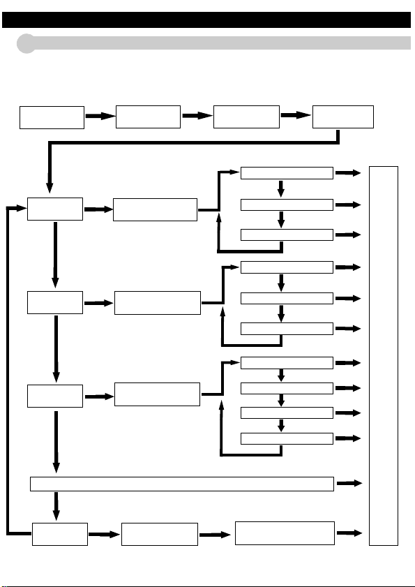
04 Operation Instruction
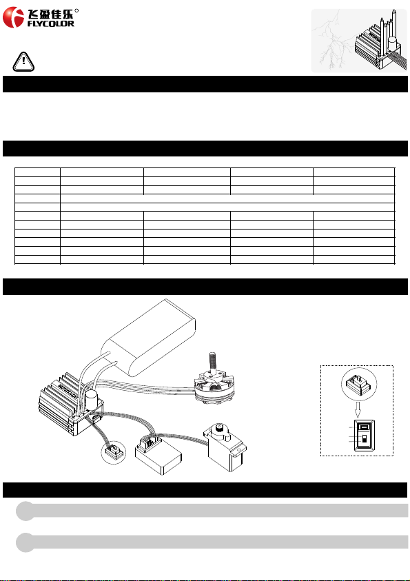
1Connect all the equipments as the wiring diagram, and go to next step.
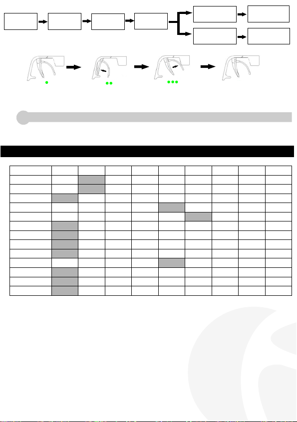
05 Setting options
Set ting op tions
1.Run ning Mo de
2.F ixed Ar ea
Acc elera tor
3.I nitia l Brake Fo rce
4.Low Vo ltage
Pro tecti on
5.Sta r t M ode
(Pu nch)
6.PWM
8.Max B rake Fo rce
9.Dra g Brake F orce
7.Max R evers e Force
10.T iming
11.M otor Di rectio n
Adj ustme nt
12.O ver hea t
Pro tecti on
13.L ipo Cel l s
Opt ion1# Opt ion2# O ption3 #
For wa rd with
bra ke
Fo r w ard and
re verse w ith
br ake
For wa rd and
rev erse
Opt ion4# O ption5 # Opt ion6# O ption7 # Option 8# Op tion9 #
6%9%12%
0%5%10%2 0%30%40 %50%60%
Non -
pro tecti on 2.6V 2.8V 3.0 V 3.2V 3.4V
Lev el 1 Lev el 2 Lev el 3 Lev el 4 Lev el 5 Leve l 6 Lev el 7 Level 8 Level 9
8KH z 12KHz
25% 50%75%1 00%
50%6 0%70%80%90%10 0%
0%5%10%2 0%40%60 %80%100%
0°3.75°7. 5°11.25°1 5°18.75°22.5°2 6.25°
For wa rd Rever se
Pro tecti on Non-
Pro tecti on
Aut o 2S 3S
1.R unnin g Mode:
For wa rd with br ake : only f or ward, re verse th rottle i s brake, n o Revers e, it's ma inly use d for raci ng. ●
For wa rd and rev erse wit h brake : wi th rever se funct ion, whe n push thr ottle fr om forward t o revers e area, RC c ar is in the b rake sta te and thr ottle. ●
mu st be back t o the midd le point . RC car wil l revers e when mot or stops r otatin g .This mo de is used f or pract ice.
For wa rd and rev erse : Pus h thrott le from mi ddle poi nt to reve rse area , motor wi ll rotat e revers e immed iately. This mod e is used fo r rock cra wler. ●
: 6% 9% 1 2% ,cho ose as per sonal pr eferen ce .2.Fix ed Area A cceler ator
3.I nitia l Brake Fo rce:th e brake fo rce on mot or when br ake is in th e initia l positi on of thro ttle.
:To protec t batter y da mage fro m over dis chargi ng .ESC w ill moni tor batt er y voltag e during r unning p rocess , once vol tage is 4.L ow Volt age Prot ection
low er than s et value , it will cu t off motor output .
5.Sta r t M ode(Pu nch):9 l evel, de fault is 6 l evel, ch oose the a ppropr iate acc elerat ion acco rding to t he field an d person al pref erence . The high er level ,
the f aster t he start acce lerati on , but hig h demand f or batte r y d ischar ging abi lity( it w ill caus e abnorm al start whe n batter y ca pacity i sn't eno ugh ).
:Wor king fre quency , 8KHz、12K Hz,choo se the app ropria te worki ng frequ ency acc ording t o the feat ures of mo tor and ba ttery.6 PWM
:4 op tions : 2 5% 50% 75% 1 00% , diffe rent opt ion with d ifferen t force. R ecomme nd to use th e smalle r option s, to avoi d crashi ng 7.Max R evers e Force
for t he forc e is too hea vy when ba ck up.
:ES C with po tentia l brake th e max. bra ke force i s that the b rake for ce when pu sh throt tle stic k to the bra ke limit p oint. Ch oose the 8 .Max Bra ke Force
app ropri ate brak e force ac cordin g to perso nal pref erence a nd speci fic situa tion
:Pu sh thro ttle sti ck from fo r wa rd area to m iddle po int,pr oduce br ake forc e for moto r,it's ea sy for slo wing dow n.star ti ng the tur ns.9.Dra g Brake F orce
: Opt ions :0° ,3. 75° ,7.5° ,11. 25° ,15°(def ault) ,18 .75° ,22.5° ,2 6.25° ,Pu rpose a re:10. Timing
Com patib le with di f ferent t ypes mot or. If n ot work wi th defau lt timi ng , pleas e change t he appro priate t iming. ●
Cha nge mot or Max.R PM by chan ging tim ing. Timi ng is high er , outpu t RPM is fas ter, powe r consum ption is b igger. ●
Mak e motor w ork in the b est effici ency poi nt by chan ging tim ing.●
Aut o timin g can chan ge timin g betwee n 0°and 30°aut omatic ally . ●
:Ch ange mo tor rota tion dir ection w ith this o ption.11.M otor Di rectio n Adjust ment
:ES C or moto r temper ature is v er y high ( ove r 95°), this o ption de cides if c ut off the mo tor outp ut, defa ult is pro tectio n.12. Over he at Prote ction
Aut o : count L ipo cell s automa ticall y; 2S,3S : choose t he corre spondi ng value s accord ing to bat tery cells n umber.13. Lipo Ce lls:
*Sha dow par ts ar e factor y de fault va lue
2
12
R
●18 A
●25 A
●35 A
●45 A
Lig h tnin g
ser i es
● Well-designed drive firmware for brushless sensor -less 3 phase motor, smooth, delicate handle of speed control .
● With high performance MCU, low internal resistance MOSFET and imported components. High reliability, with low impedance circuit board, strong resistance
current,less heat production.
● 8 acceleration options. Applied for all kinds of RC cars.
● 8 timing options, make motor work with the best efficiency.
● Multiple protection functions: battery low voltage protection, over temperature protection, throttle signal loss protection, motor blocked protection, etc.
● Easy to use, set parameters with radio and programming card ,according to sound prompt.
Mod el
Con t. Curr ent
Bur st Curr ent
Bat tery
BEC
Mot or supp or t
Hea t-diss ipatin g
Sui table C ar
Mot or Type
Dim ensio n
Weig ht
18A 2 5A
Lin ear BEC ; 2S Lipo o r equiva lent NiH M BEC outp ut:6V/2 A; 3S LIPO o r equiva lent Ni H M BEC out put:6V/ 1A
LiP O:2-3 S;NIHM:6 -10cel l
≥ 12 T(2040 s ize Moto r) ≥ 9T(36 50 size Mo tor) ≥ 5.5T (3650 si ze Motor )
Alu minum H eatsin k
1:1 8/1:1 6 1:1 8/1:1 6 1:10
35A 4 5A
34* 29*19 mm 34* 29*19 mm 34* 29*19 mm 34*29 *31mm( Includ ing Fan)
40g 4 2g 46g 54g
A-C W0180 03 A-CW0 25003 A-C W0350 03 A-CW0 45003
50A 9 0A 190 A 260A
≥ 12 T(2040 s ize Moto r)
1:1 8/1:1 6
Alu minum H eatsin k Alumin um Heats ink Alum inum Hea tsink + Fa n
Brushless sensorless Brushless sensorless Brushless sensorless Brushless sensorless
*Please ensure all solder joints are insulated with
heat shrink where necessary
Receiver
ESC
Bat tery
Switch
see detail
“Se t”
“On ”
“Of f ”
Gear
Motor
Note: We strongly advise the use of battery connections that do not allow reverse polarity , or ESC will be damaged.
Please disconnect the battery and ESC , if not use for a long time to avoid damaging battery and accidents.
First time to use remote control transmitter or change the parameters ,like throttle middle point, ATL, EPA , throttle range will be set again.
Remote control transmitter ABS must be set as “OFF”, set throttle channel direction as “REV”, set throttle trim as “0”, EPA/ATL clockwise and
anticlockwise direction of throttle channel are set as 100% ( Max.), or it may cause no work or misoperation.
Set throttle range ( refer the setting process of throttle range)
3
After Wire connection and basic setting, and motor prompt tone finshed, the ESC can work.
● After setting ,Turn off the power , and turn on again, the ESC will ready for working.
● Indicator function : red light flashes when motor run.When motor run with full throttle ,green light flashes.
Reset to factory default setting: press the “set” button more than 3 seconds, then red and green lights will flash 3 times, all the setting will ●
to be the factor y tting . (this operation will not work during the process of setting throttle range default se or programming)
Turn off ESC power
switch and turn on
transmitter power
switch.
Press”Set” button
and turn on power
supply switch
Green LED flashes
“N” times indicate
battery cells No.
Red LED flashed
continuously.
Continuously press
“Set”button.
Release “Set”button
Red LED stops
flashing.
Enters to throttle
range setting
(See Pic. below)
Enters to Programming
procedure.
(See page 2)
1.Kee p the throttle sti ck in
th e n e u t ra l p o s i ti on .P r e s s
"set" button,green LED flashes
once.Neutral point of the throttle
is now memorized.
2.Move the throttle stick to full
forward position,Then press the
“Set”button, the green LED will
flashes twice.Now the full forward
throttle position is memorized.
3.Move the throttle stick to the
full reverse position.Press the
”Set” button and green LED will
flashes 3 times. Full reverse
throttle is memorized.
4.Return throttle stick to
neutral position. All ranges
now configured.