MB Connect Line mbNET.mini User manual

User Manual
Version: 2.2.1 - EN | Mar 28th, 2022
User Manual
Version: 2.2.1 - EN | Mar 28th, 2022
.

By purchasing the mbNET.mini router, you have chosen a product made in Germany.
Our products are produced exclusively in Germany, which guarantees the highest quality and safeguards jobs
in Europe.
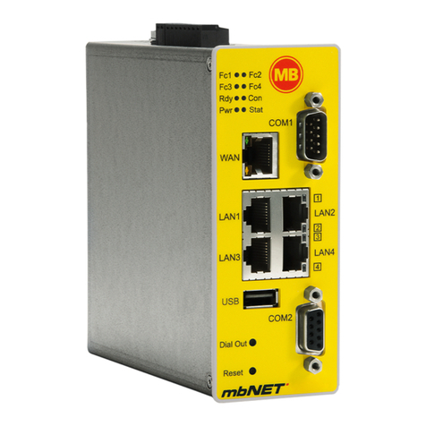
The latest information and updates can be found on our homepage www.mbconnectline.com.
We welcome comments, suggestions for improvement or constructive criticism at any time.
SIMPLIFIED EU DECLARATION OF CONFORMITY
Hereby, MB connect line GmbH declares that the radio equipment types MDH 862 EU; MDH 863;
MDH 866 EU; MDH 867 are in compliance with Directive 2014/53/EU.
The full text of the EU declaration of conformity is available at the following internet address:
www.mbconnectline.com
Issued by:
MB Connect Line GmbH
Fernwartungssysteme
Winnettener Str. 6
91550 Dinkelsbühl, Germany
Tel:
+49 (0) 700 622 666 32 /
+49 (0) 700MBCONNECT
Website:
www.mbconnectline.com
Copyright © MB Connect Line GmbH 1997 - 2022
Page 2 von 131 | Version: 2.2.1 - EN | Mar 28th, 2022 |

Table of contents
1 General................................................................................................................................................... 6
2 Safety instructions................................................................................................................................9
3 Legal information..................................................................................................................................9
4 Notes on Cyber-Security....................................................................................................................10
5 Maintenance.........................................................................................................................................11
6 Disposal of old devices......................................................................................................................11
7 Functional Overview / Specifications............................................................................................... 12
8 Scope of Supply..................................................................................................................................13
9 Displays, controls and connections.................................................................................................15
10 Interface assignment.......................................................................................................................... 18
10.1 Pinout of the terminal block on the bottom of the device...........................................................18
10.2 Pinout of LAN/WAN ports on the front panel of the device........................................................18
10.3 Pinout of the USB port on the front panel of the device............................................................18
11 Getting started.....................................................................................................................................19
12 Initial configuration.............................................................................................................................21
12.1 Initial configuration via RSP mbCONNECT24 V 2.0..................................................................22
12.1.1 Account request - Software download........................................................................... 23
12.1.2 Download mbDIALUP.....................................................................................................23
12.1.3 Install mbDIALUP........................................................................................................... 23
12.1.4 Register your account for mbCONNECT24................................................................... 24
12.1.4.1 1 / 3 "Account Setup"..................................................................................................26
12.1.4.2 2 / 3 "Contact Person".................................................................................................27
12.1.4.3 3 / 3 "Further Information"...........................................................................................28
12.1.5 Completion of registration...............................................................................................29
12.2 Connect to RSP mbCONNECT24..............................................................................................30
12.3 mbCONNECT24 Configuration...................................................................................................32
12.3.1 Changing your password................................................................................................32
12.3.2 Creating a project...........................................................................................................34
12.3.3 Create a new device...................................................................................................... 36
12.3.4 Create a configuration....................................................................................................38
12.3.4.1 LAN Settings................................................................................................................39
12.3.4.2 Wi-Fi Settings.............................................................................................................. 40
12.3.4.3 Internet Settings...........................................................................................................43
12.3.4.4 WAN Settings.............................................................................................................. 47
12.3.4.5 Modem Settings...........................................................................................................48
12.4 Transferring the configuration to the Device..............................................................................49
12.4.1 Download to PC............................................................................................................. 50
Table of contents | Page 3 of 131

12.4.1.1 Importing the configuration into the device................................................................. 50
12.4.2 Prepare for Synchronization...........................................................................................52
12.4.3 Transferring configuration to the device - via mbDIALUP..............................................53
12.5 Access to devices and machines...............................................................................................55
12.6 Quit the mbCONNECT24 session..............................................................................................56
12.7 Initial configuration via mbCONNECT24 V 1.x...........................................................................57
12.7.1 Adding a new device (mbCONNECT24 V 1.x).............................................................. 58
12.7.1.1 Description - all devises..............................................................................................59
12.7.1.2 Network (MDH 860, 861, 862, 863)............................................................................60
12.7.1.3 Internet.........................................................................................................................61
12.7.1.3.1 WAN device (MDH 860)...........................................................................................61
12.7.1.3.2 WAN device (MDH 861, 862)...................................................................................62
12.7.1.3.3 Wi-Fi device (MDH 863)...........................................................................................63
12.7.2 Transferring the configuration to mbNET.mini................................................................64
12.7.2.1 Download configuration to PC - via USB....................................................................65
12.7.2.2 Transfer configuration to the device - via CTM...........................................................66
12.7.2.3 Transferring configuration to the device - via mbDIALUP...........................................67
12.8 Initial configuration of the router via its device web interface.....................................................68
12.8.1 First Start........................................................................................................................70
12.8.2 Device State................................................................................................................... 74
12.8.2.1 Five Step Status Check...............................................................................................75
12.8.2.2 API for status queries..................................................................................................78
12.8.3 Diagnostics......................................................................................................................79
12.8.4 Tags................................................................................................................................80
13 Configuring your Router in the Remote Service Portal (V 2.x)......................................................81
13.1 System Settings..........................................................................................................................82
13.2 Mail Settings............................................................................................................................... 83
13.3 Firewall........................................................................................................................................84
13.3.1 Global Firewall Settings..................................................................................................84
13.3.2 Firewall Rules.................................................................................................................87
13.3.2.1 Firewall Settings - Create new WAN > LAN...............................................................89
13.3.2.2 Firewall Settings - Create new LAN > WAN...............................................................92
13.3.2.3 Firewall Settings - Create new Forwarding.................................................................94
13.3.2.4 Firewall Einstellungen - Create new 1:1 NAT.............................................................96
13.3.2.5 Firewall Einstellungen - Create new SimpleNAT........................................................ 97
13.4 Digital I/O....................................................................................................................................98
13.5 Alarm management.....................................................................................................................99
13.5.1 Functions for a digital input..........................................................................................100
13.5.2 Functions for a digital output........................................................................................101
13.6 VPN...........................................................................................................................................102
13.7 User Administration...................................................................................................................103
13.8 NTP...........................................................................................................................................104
13.9 Time Zone.................................................................................................................................106
13.10 Web Server...............................................................................................................................107
13.11 Direct Device Web2go..............................................................................................................108
Page 4 von 131 | Version: 2.2.1 - EN | Mar 28th, 2022 |

13.12 Logging......................................................................................................................................109
14 Configuring Your Router in the Portal (V 1.x)............................................................................... 110
14.1 System > Settings.....................................................................................................................111
14.1.1 System Settings............................................................................................................111
14.1.2 Time Settings................................................................................................................111
14.1.3 Mail Settings.................................................................................................................112
14.2 System > WEB......................................................................................................................... 112
14.3 System > USB..........................................................................................................................113
14.4 System > Logging.....................................................................................................................114
14.5 Security > Firewall General......................................................................................................114
14.6 Security > WAN>LAN...............................................................................................................116
14.7 Security > LAN>WAN...............................................................................................................117
14.8 Security > Forwarding...............................................................................................................118
14.9 Security > NAT......................................................................................................................... 119
14.10 Alarm management > Input......................................................................................................120
14.11 Passwords (Password Settings)...............................................................................................121
15 Factory settings on delivery............................................................................................................122
16 Loading the factory settings........................................................................................................... 122
17 Firmware update............................................................................................................................... 123
17.1 Firmware update via USB........................................................................................................ 124
17.2 Firmware update via RSP mbCONNECT24.............................................................................125
18 Technical data industrial router mbNET.mini MDH 860 – MDH 867.............................................127
Table of contents | Page 5 of 131

1 General
Purpose of this documentation
This user manual describes the functions and use of the mbNET.mini router MDH86x.
Please read carefully and retain this information.
Validity of this documentation
This manual is valid for the router mbNET.mini MDH 860, MDH 862 EU, MDH 862 AT&T, MDH863,
MDH 866 EU, MDH 866 AT&T, MDH 867, from hardware version HW02* with firmware version from V 2.2.0.
Prerequisites / additional required components
The following end devices are suitable for connecting to the mymbCONNECT24.virtual server:
•standard Windows PC with network interface (ethernet interface)
•USB stick recommended format: FAT32 or ext3; maximun size: 4 GB (FAT32), 16 GB (ext3)
•network cable
•internet access
Additional required software
•mbCONNECT24
mbCONNECT24 is the central portal for secure remote maintenance on the internet.
•mbDIALUP ** from version V 3.8
To establish a secure VPN connection to the portal mbCONNECT24 you need the remote client soft-
ware mbDIALUP.
•mbCHECK ** from version V 1.1.2
The program checks that at least one of the 80TCP, 443TCP or 1194TCP ports is enabled in the fire-
wall. One of these ports is needed by mbDIALUP and the device (router) in conjunction with mbCON-
NECT24. You will then be notified whether connection via mbDIALUP to the portal is possible.
The Simplify³-Logo on the nameplate indicates that
the SIMPLY.connect function is available on the device.
SIMPLY.connect is a web application that helps you to
set up a device (mbNET) in the Remote Service Portal
mbCONNECT24. More information is available at:
https://simplyconnect.mbconnectline.com/
* You will find the hardware version on the device nameplate.
** The latest version can be downloaded free of charge from www.mbconnectline.com
Page 6 von 131 | Version: 2.2.1 - EN | Mar 28th, 2022 |

Release notes:
Version Date Comment
V 1.9 DR01 June 12th, 2017 Previous version V 1.9
V 1.9 DR02 Jan 25th, 2018 General changes (text and graphics)
V 1.9 DR03 May 4th, 2018 Note in the Technical Specifications on missing CE conformity for MDH 862 AT&T.
V 2.0 Mar 11th, 2019 The following new device types have been added: MDH 865, MDH 866 EU, MDH
866 AT & T and MDH 867. Technical feature of the new types: 3 x LAN interface, 1 x
WAN interface with failover function WAN > Modem / Wi-Fi.
V 2.0 DR01 Apr 29th, 2019 Correction in chapter 11.3 Initial configuration via the device web interface: "You
must enter the IP address of the mbNET.mini (192.168.0.253) as the default gateway
and as the preferred DNS server."
This information is incorrect and has been deleted.
V 2.0 DR02 Oct 1st, 2019 The chapter ""Maintenance"" has been added, with the remark to check at regular in-
tervals the actuality of the firmware installed on the device.
V 2.0.6 Nov 18th, 2019 For devices with hardware version HW 02 and firmware from V 2.0.6 , the two I/Os
can be configured independently of each other as a digital input or digital output.
V 2.0.6 DR01 Jan 14th, 2020 Changed data (frequencies and target region) for devices with LTE (4G) module
(MDH 862 EU, MDH 866 EU) with hardware version: HW03
V 2.0.8 May 11th, 2020 Change of access data for the device web interface (see chapter "Factory settings on
delivery").
An individual device password now applies to the devices described above under
"Validity of this documentation".
You will find this password on the back of the device.
V 2.0.8 DR01 July 6th, 2020 Add the transmission power of radio modules in the technical data.
V 2.0.8 DR02 Jan 20th, 2021 Adding chapter 13.4, "Digital I/O"
Change of alarm management for devices with freely selectable I/Os (only in con-
junction with the remote service portal V 2.x). See chapter 13.5, "Alarm manage-
ment".
Change of server locations for RSP mbCONNECT24 => server location CHINA has
been replaced by server location ASIA. Please refer chapter 12.8.1, "First Start" >
Cloudserver.
V 2.2.0 June 28th, 2021 Description of the SIMPLY.connect functionality (S3).
Extension of the LED light codes for devices with SIMPLY.connect functionality (S3).
Description of the API for the status display in chap. Device State.
V 2.2.0 DR01 Oct 27th, 2021 NOTICE of data loss when switching off the mbNET, before the mbNET has picked
up its configuration from the mbCONNECT24 portal - see chapter "First Start".
Correction of the performance data for the Digital Outputs: Changed from 1.5 A to 0.5
A per output.
V 2.2.1 Mar 28th, 2022 Addition of the chapter "Disposal of old devices"
Update of chapters "Scope of Supply" and "Technical data"
Additional documentation
"First steps mbCONNECT24" - This document describes the initial steps and actions that are necessary to
connect an mbNET industrial router to the portal with the remote client mbDIALUP.
Currently manuals and more information
The latest manuals and more information about products related to secure remote maintenance can be found
on www.mbconnectline.com
General | Page 7 of 131

Use of open source software
General
Our products include, among other things, open source software, which is manufactured by a third party and
has been published for free use by anyone. The open-source software is available under special open-source
software licences and copyright of third parties. In principle, each customer can use open source software
free of charge under the licence terms of the respective manufacturers. The customer's right to use the open
source software for purposes other than those for which our products were intended is regulated in detail by
the relevant open source software licences. The customer may freely use the open source software as set out
in the respective valid licence, beyond the intended purpose of the open source software in our products. In
the event that there is a contradiction between the licensing terms of one of our products and the respective
open source software licence, the respective applicable open source software licence shall take priority over
our licensing terms if the respective open source software is affected by this.
Use of the open source software is free of charge. We do not charge any usage fees or similar charges for the
use of open source software included in our products. Customer use of open source software in our products
is not part of the profit that we obtain from the contractual remuneration. All open source software programs
contained in our products are in the available list. The most important open source software licenses are listed
in the Licences section at the end of this publication.
If programs that are included in our products are under the GNU General Public License (GPL), GNU Less-
er General Public License (LGPL), the Berkeley Software Distribution (BSD), the Massachusetts Institute of
Technology (MIT), or other open source software license, which requires that the source code be made avail-
able, and this software was not already supplied with our product on a disk or in the source code, we will send
this at any time upon request. If we are required to send this on a disk, there will be a flat rate charge of €35.00.
Our offer to send the source code upon request, shall automatically end 3 years after delivery of the respective
product to the customer.
Requests must, where possible, be sent to the following address with the product's serial number:
MB connect line GmbH Fernwartungssysteme · Winnettener Str. 6 · 91550 Dinkelsbühl GERMANY
Special liability provisions
We assume no responsibility or liability if the open-source software programs included in our products are
used by customers in a manner that no longer corresponds to the purpose of the contract which serves as
the basis for the purchase of our products. This applies in particular to any use of the open source software
programs outside of our products. The warranty and liability provisions, which stipulate the applicable open
source software license for the corresponding open source software, as listed below, apply to the use of open-
sourcesoftware beyondthecontractual purpose.In particular, we are alsonot liable if the open source software
in our products or the entire software configuration in our products is changed. The warranty contained in
the contract, which forms the basis for the purchase of our products, applies only to unchanged open source
software and the unchanged software configuration in our products.
Open source software used
For a list of the open source software used in our products, visit https://www.mbconnectline.com/down-
loads/open-source-software-licenses.txt.
Page 8 von 131 | Version: 2.2.1 - EN | Mar 28th, 2022 |

2 Safety instructions
•The router is built to the latest technological standards and recognized safety standards (see Declara-
tion of Conformity).
•The router must be installed in a dry location. No liquid must be allowed to get inside the router, as this
could result in electric shocks or short circuits.
•The router is for indoor use only.
•Never open the router chassis. Unauthorized opening and improper repair can pose a danger to the
user. Unauthorized modifications are not covered by the manufacturer's warranty. Opening up the de-
vice voids the warranty.
•The router must be disposed of in line with European regulations and German legislation on electronics
and electronic devices and not in general household waste. The device should be disposed of accord-
ingly.
In the present operating instructions the following notes are used:
Notice type Description
An advice signifies additional information and indications such as cyber-security that
assists in the assured handling with the system.
ATTENTION This note indicates a possible risk of damage to hardware and / or software.
3 Legal information
Qualified Personnel
The product/system described in this documentation may be operated only by personnel qualified for the spe-
cific task in accordance with the relevant documentation, in particular its warning notices and safety instruc-
tions. Qualified personnel are those who, based on their training and experience, are capable of identifying
risks and avoiding potential hazards when working with these products/systems.
Proper use
The mbNET.mini router may be used only as described in the manual.
Disclaimer
In this manual all technical information, data and instructions for installation, operation and maintenance are
based on our previous experience and insights to the best knowledge. For the details, illustrations and descrip-
tions in these instructions, no claims can be deduced. We assume no liability for damage due to:
•disregard of these operating instructions
•improper use
•technical modifications
Subject to technical and content changes.
Trademarks
The use of any trademark not listed herein is not an indication that it is freely available for use.
Safety instructions | Page 9 of 131

4 Notes on Cyber-Security
To prevent unauthorized access to facilities and systems, observe the following security recommendations:
General
•Periodically ensure that all relevant components meet these recommendations and any additional inter-
nal security policies.
•Perform a security assessment of the entire system. Use a cell protection concept with suitable prod-
ucts.
For example, "ICS-Security-Kompendium" from the BSI (Federal Office for Security in Information
Technology, Bundesamt für Sicherheit in der Informationstechnik)
https://www.bsi.bund.de/SharedDocs/Downloads/DE/BSI/ICS/ICS-Security_kompendium_pdf.html
shortened URL: http://bit.ly/1rP9znm
Physical access
•Restrict physical access to security-relevant components to qualified personnel.
Security of the software
•Keep software/firmware updated.
°Stay informed about security updates for the product.
°Stay informed about product updates.
You can find information about this at: www.mbconnectline.com
Passwords
•Define rules for the use of the devices and assigning passwords.
•Change passwords regularly, to increase security.
•Use only passwords with a high password strength. Avoid weak passwords such as "password1",
"123456789".
•Make sure that all passwords are protected and inaccessible to unauthorized personnel.
•Do not use the same password for different users and systems.
Page 10 von 131 | Version: 2.2.1 - EN | Mar 28th, 2022 |

5 Maintenance
Our devices are maintenance-free units. If a device shows signs of damage or malfunctions, the device must
be put out of operation immediately and secured against unintentional operation.
NOTICE
Regardless of the maintenance-free hardware, there is a need for action in terms of IT security.
•Keep the software / firmware up to date.
•Note the "Information about cyber-security".
•Keep yourself informed about security updates of the product.
Information can be found at: www.mbconnectline.com
6 Disposal of old devices
In the interests of environmental protection, final holders must collect old devices separately from unsorted
municipal waste at the end of their service life.
Old batteries and accumulators that are not enclosed by the old device, as well as lamps that can be removed
fromtheolddevice without destroyingthem,must be separatedfromthe old deviceinanon-destructive manner
before they are handed over to a collection point.
The final holder is responsible for deleting personal data on the old devices to be disposed of.
MB connect line offers the possibility of returning and disposing of old devices. Details can be found at
www.mbconnectline.com/disposal.
Do not despose of old devices into household waste!
Only for EU countries:
Dispose of the device in accordance with the Waste Electrical and Electronic Equipment Directive 2012/19/
EU - WEEE.
Maintenance | Page 11 of 131

7 Functional Overview / Specifications
Brief description
The industrial router mbNET.mini offers you optimum flexibility and security, making remote communication
with your systems both easy and secure. It offers secure IP-based access to Ethernet devices and networks
through the remote service platform mbCONNECT24. Therefore, it is not only suitable for remote maintenance
applications but also for tasks such as alerts and M2M communication.
Thanks to its compact design, the router will fit into any switch cabinet and provides the perfect system for
connecting to different components. The router can be configured via the portal mbCONNECT24 (mymbCON-
NECT24.mini, -.midi, -.maxi, -.hosted, -.virtual).
Performance characteristics
•The router can be fully configured via the portal mbCONNECT24, mymbCONNECT24.mini, -.midi,
-.maxi, -.hosted, -.virtual.
•Can connect to machines and systems via LAN, WAN, Wi-Fi or modem.
•Deployable worldwide using mobile communications plus access via LAN and Internet.
•Secure connection using an integrated firewall with IP filter, NAT, port forwarding and VPN.
•USB over IP capable
With the function USB over IP the USB port of the mbNET.mini is transmitted or made available direct-
ly to the PC of the mbDIALUP user. All devices connected to the USB port of the mbNET.mini (USB
memory, PLC, webcams, etc.) are automatically available on this PC.
•SEARCHoverIP capable
With the SEARCHoverIP function, you can also find your PLC via remote maintenance in the network.
For example, "virgin" SIEMENS controllers can be found and configured remotely in the network. Fur-
thermore the search function for controls of the brands SchneiderElectric, Rockwell, Beckhoff and Pilz
is supported.
•Integrated Ethernet switch 3-port or 4-port - depending on the device type -
•4G versions support GPRS, EDGE, UMTS, HSPA+, LTE
•2 pieces I/Os. These connectors can be independently configured as a digital input or digital output.
•OpenVPN security protocol
•Solid metal case for DIN rail mounting
•Ideal for M2M applications
•Secure connection to the Remote Service Portal mbCONNECT24
Page 12 von 131 | Version: 2.2.1 - EN | Mar 28th, 2022 |

8 Scope of Supply
Check the package contents for completeness:
All device types
1 x mbNET.mini industrial router (Fig.
representative) 1 x Quick Start Guide
Item No.: 8.002.702.03.00 1 x Device ID card
If one of these parts is missing or
damaged, contact the following
address:
MB connect line GmbH
Winnettener Str. 6
D-91550 Dinkelsbühl
Tel.: +49 (0)9851/58 25 29 0
Fax: +49 (0)9851/58 25 29 99
Keep the original box as well as the original packaging material in case you need to send the device in for
repair at a later date.
Suitable accessories for ...
... types with GSM modem
MDH 862; MDH 866 ... types with Wi-Fi modem
MDH 863; MDH 867 ... all device types
GSM antenna
Item No.: 8.002.101.01.00 Wi-Fi antenna
Item No.: 8.002.107.00.00 Ethernet cable 1:1
Item No.: 8.002.201.00.00
NOTICE
You can find more accessories at www.mbconnectline.com
Scope of Supply | Page 13 of 131

Page 14 von 131 | Version: 2.2.1 - EN | Mar 28th, 2022 |
9 Displays, controls and connections
View of front of the device
MDH 860 MDH 862 MDH 863 MDH 866 MDH 867
3 x LAN
1 x WAN
USB
4 x LAN
4G module
USB
4 x LAN
Wi-Fi
USB
3 x LAN
1 x WAN
4G module
USB
3 x LAN
1 x WAN
Wi-Fi
USB
Connections, interfaces and buttons
Designation Description
ANT
SMA antenna connector:
•SMA (MDH 861, MDH 862, MDH 865, MDH 866)
•RP SMA (MDH 863, MDH 867)
Main SMA antenna connector for use with one antenna
Div.
SMA antenna connector (combined with "Main") of
•a second antenna (macrodiversity)
•a MIMO antenna (microdiversity)
WAN Router WAN connection (customer network, DSL router).
LAN 1 - 3 Local network connection (e.g. machine network, network data transfer).
USB
•Transfer of configuration from USB stick to the device.
•Transfer of firmware from USB stick to the device.
•Access to free application data via SFTP.
•Connection of USB devices (USB memory, PLC, webcams, etc.)
Function This button has 4 functions and is used according to the status.
1. Establishing connection to portal (depending on configuration)
2. Accepting firmware or configuration from USB stick
3. Loading factory settings
4. Activate the SIMPLY.connect *function
Reset Pushing this button restarts the device (so-called cold start).
Displays, controls and connections | Page 15 of 131

LED light codes
Designation LED-Status Description
off Device power source is switched off or device is not connected to power
source/power pack.
Pwr (Power)
green on Power source is connected to terminal block and switched on.
flashing After the system has been checked and started (duration approx. 25 sec),
the LED flashes for the duration of the starting up process (approx. 90 sec).
Rdy (Ready)
green on The device is ready for operation.
The Con LED signals the connection status to the Internet and portalserver.
off No connection to Internet or portal.
flashing (3Hz) Internet or VPN connection being established.
flashing (1,5Hz) Connection to portal server has been established.
Con (Connect)
orange
on Connection to the Internet has been established.
Light codes of the LED Usr directly after the start of SIMPLY.connect *-capable devices:
flashes briefly
at intervals
(500 msec on -
1500 msec off)
SIMPLY.connect is available but not activated.
This means: The SIMPLY.connect * function is supported by the device.
As long as the function is not activated by pressing the Function button, the
device remains in "normal mode" and no further action takes place.
If you do not want to use the Simply.connect *function, simply ignore this
display.
Usr (User)
orange
on SIMPLY.connect * is activated.
SIMPLY.connect * is active after the function button has been pressed.
The device tries to establish a connection to the SIMPLY.connect *server.
Light codes of the LED Usr during operation:
flashing (3Hz) Firmware on USB stick ready to be updated.
flashing (1,5Hz) Portal configuration on USB stick ready to be transferred.
Usr (User)
orange
on Firmware or configuration is being copied to the device.
orange flashing Network data transfer active
green on Transfer rate = 100 MBit/sWAN LED
green off Transfer rate = 10 MBit/s
orange flashing Network data transfer active
green on Transfer rate = 100 MBit/sLAN LED 1 – 3
green off Transfer rate = 10 MBit/s
* SIMPLY.connect is a web application that supports you when creating a device (industrial router mbNET) in the
Remote Service Portal mbCONNECT24.
You can find more information about SIMPLY.connect on our website at: https://simplyconnect.mbconnectline.com/
Page 16 von 131 | Version: 2.2.1 - EN | Mar 28th, 2022 |
View of bottom of device
-0 V DC connection
+Power source connection 10 - 30 V DC
FE Functional earth
1* I/O 1
2* I/O 2
* I/O 1 and I/O 2 can be configured independently of each other as digital input or digital output.
View of device from left Device dimensions - mm
Antenna connection
SIM-card slot
| Page 17 of 131

10 Interface assignment
10.1 Pinout of the terminal block on the bottom of the device
-0V DC connection
+Power source connection 10-30V DC
FE Functional earth
I/O
Digital Input 1 (10 - 30V DC)
1*Digital Output 1 (max. 0.5 A @24 V)
Digital Input 1 (10 - 30V DC)
2*Digital Output 1 (max. 0.5 A @24 V)
* I/O 1 and I/O 2 can be configured independently of each other
as digital input or digital output.
Image 1: Terminal strip on the bottom side
Image 2: Example: I/O 1 = input, I/O 2 = output
10.2 Pinout of LAN/WAN ports on the front panel of the device
Signal
1TX+
2TX-
3RX+
4Not connected
5Not connected
6RX-
10.3 Pinout of the USB port on the front panel of the device
Signal
1VCC (+5V)
2- Data
3+Data
4GND
Page 18 von 131 | Version: 2.2.1 - EN | Mar 28th, 2022 |
11 Getting started
The device is intended to be installed in switch cabinets and designed to be mounted on top-hat rails (ac-
cording to DIN EN 50 022).
DIN rail mounting:
Insert the device into the DIN rail. To do this, position the upper guide of
the bracket on the rail on the back of the device and then press the de-
vice downwards against the rail until fully inserted.
Depending on the device, connect an antenna, and insert a SIM card.
NOTICE
The SIM card used must be Internet- / VPN-enabled. If you have any questions, contact your cell phone
operator.
Connect the mbNET.mini to the power supply
NOTICE
Before connecting the device to a network or PC, first ensure that it is properly connected to a power supply,
otherwise it may cause damage to other equipment.
You should therefore follow the instructions given below.
1. Connect equipotential bonding to the functional earth (FE).
2. Then connect the device to a supply voltage (10 - 30 VDC).
Make sure the polarity is correct!
-0 V DC connection
+Power source connection 10 - 30 V DC
FE Functional earth
1* I/O 1
2* I/O 2
* I/O 1 and I/O 2 can be configured independently of each other as digital input or digital output.
Getting started | Page 19 of 131

Start sequence
1. After turning on the power supply, the LED Pwr lights up.
2. As soon as the system has been checked and started (duration approx. 25 sec), the Rdy LED flashes
for the dura-tion of the starting up process (approx. 90 sec).
3. When both LEDs - Pwr and Rdy - light up, the mbNET is ready for operation.
4. With SIMPLY.connect * capable devices, the Usr LED flashes briefly at intervals (500 msec ON -
1500 msec OFF). That means: SIMPLY.connect is available but deactivated.
* The SIMPLY.connect function is only available for devices with the Simplify³ logo * (see device
nameplate).
SIMPLY.connect is a web application that supports you when creating a device (mbNET) in the Remote
Service Portal mbCONNECT24. You can find more information at:
https://simplyconnect.mbconnectline.com/
NOTICE
If you want to forego the support of SIMPLY.connect, ignore the flashing LED Usr and simply continue with
the commissioning / configuration of the device.
For further support on the mbNET.mini, visit our website on www.mbconnectline.com
Page 20 von 131 | Version: 2.2.1 - EN | Mar 28th, 2022 |
Other manuals for mbNET.mini
1
Table of contents
Other MB Connect Line Network Hardware manuals
Popular Network Hardware manuals by other brands

AMX
AMX NXF Dimensional drawing

Ciara
Ciara Astro PB60S user guide

ZyXEL Communications
ZyXEL Communications PLA450 Series quick start guide

IEI Technology
IEI Technology PUZZLE-M801 user manual

Security Camera King
Security Camera King NVR-LT-128 user manual

Foxconn
Foxconn RPQN O-RU Installation and operating guide