MC Electronics GLM KIT User manual

––
INSTRUCTIONS FOR USE
NO. 1713-GLM
OEM-EN
REV. 3
EN
O.E.M. VERSION (MANUFACTURERS)
GLM KIT
GRAIN LOSSES MONITOR
MONITORING SYSTEM
FOR COMBINE HARVESTERS
(sieve sensors + straw walker sensors + recovery sensors)

Instructions for use
GLM KIT
2
This product meets the EMC standards as determined in the
2004/108/EC directive and subsequent amendments
and reference to the applied EN ISO 14982 standard
Manufacturer
: MC Elettronica S.r.l.
Address
: Via E. Fermi, 450/486
Fiesso Umbertiano (ROVIGO) - ITALY
Tel. +39 0425 754713 Fax +39 0425 741130
E-mail: [email protected]
Internet: www.mcelettronica.it
Manual code
: 1713GLM-OEM-EN
Issued
: April 2019
Edition
: November 2020
MC Elettronica S.r.l. is not obliged to give notice of any further modifications of the
product.
The information given in this manual does not allow unauthorised personnel to tamper with
the product in any way.
The warranty on the equipment will no longer be valid if tampering should be detected.
© Copyright MC Elettronica 2020
2 LED for millesimal scale
3 LED for centesimal scale
4 Mechanical adjustment of monitor
5 Functions selector switch
6 Cycle LEDs
7 Delay end LED
8 Adjustment buttons

Instructions for use
GLM KIT
3
Contents
1. Rules and general warnings ................................................................................ 4
1.1 Introduction....................................................................................................... 4
1.2 Terms of the warranty....................................................................................... 5
1.3 Service.............................................................................................................. 5
2. General description .............................................................................................. 6
3. System installation............................................................................................... 7
3.1 Virtual Terminal assembly................................................................................. 9
3.2 Sensor installation........................................................................................... 10
3.2.1 Speed sensor installation......................................................................... 10
3.2.2 "RPM" sensor installation......................................................................... 11
3.3 Keyboard operation......................................................................................... 12
3.3.1 Home screen............................................................................................ 12
3.3.2 Main screen ............................................................................................. 13
3.3.3 Screen of sensor sensitivity ..................................................................... 14
3.4 Graphic interface description .......................................................................... 15
3.4.1 Home screen............................................................................................ 15
3.5 Work screen.................................................................................................... 16
3.6 Screen of sensor sensitivity ............................................................................ 17
4. Programming....................................................................................................... 18
5. User settings....................................................................................................... 19
5.1 Speed sensor calibration................................................................................. 21
6. Machine settings................................................................................................. 22
6.1 How to access the machine menu .................................................................. 22
6.2 Machine setup screens................................................................................... 23
7. Diagnostics.......................................................................................................... 25
8. Programmable parameters................................................................................. 26
9. Virtual Terminal software update ...................................................................... 27
10. ECU software update........................................................................................ 29
11. Technical data................................................................................................... 30
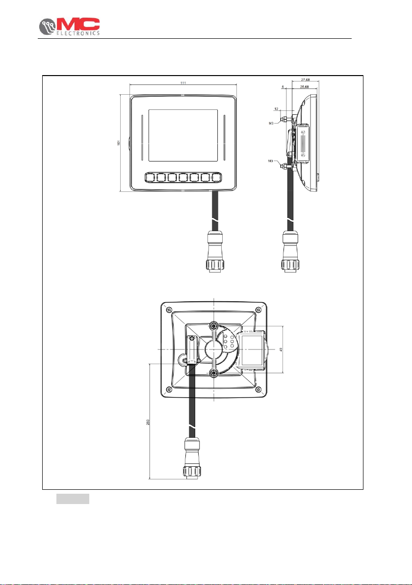
11.1 3.5” Virtual Terminal...................................................................................... 30
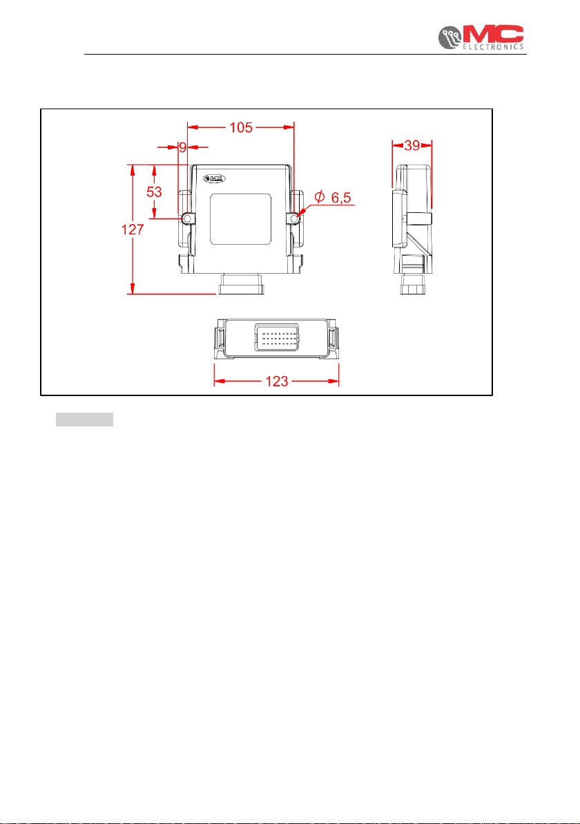
11.2 ECU GLM...................................................................................................... 30
11.3 Accessories................................................................................................... 31
11.3.1 Proximity inductive sensor ..................................................................... 31
11.3.2 Capacitive sensor .................................................................................. 31
11.3.3 Sieves / straw walker / recovery sensors............................................... 31

Instructions for use
GLM KIT
4
1. Rules and general warnings
1.1 Introduction
This instruction manual provides all specific information needed to know and correctly use
the equipment.
After buying the Monitor, read the manual carefully and refer to it any time you have doubts
on how to use the equipment or when you have to carry out maintenance operations.
Keep the manual on the machine. If this is not possible, keep it ready at hand.
ALL RIGHTS RESERVED. THIS MANUAL IS INTENDED FOR CUSTOMERS ONLY. ANY
OTHER USE ISFORBIDDEN.

Instructions for use
GLM KIT
5
1.2 Terms of the warranty
•SUBJECT OF THE WARRANTY: the warranty is applied to the product and to those
parts which are marked with the serial number or any other identification number used
by MC elettronica;
•DURATION OF THE WARRANTY: MC elettronica guarantees the GLM KIT and its
accessories for a period of 1 year from the date of manufacture (printed on the
identification label on the back of the Monitor).
The warranty covers the product and any repairs carried out within the agreed terms.
This warranty does not apply in the event of:
•accidental damage;
•improper use;
•changes which have not been agreed upon, improper installation (or set-up);
•damage caused when a equipment not manufactured by MC elettronica, which is
mechanically or electrically connected to our instruments, breaks or does not
function properly;
•force majeure events (lightning, floods, fire or other causes which do not depend
on MC elettronica).
Repairs under warranty, whichmust be carried out in the laboratories of our authorised
centres, are entirely free of charge provided the equipment is directly transported to
said laboratories or sent carriage free. Transport costs and ensuing risks are entirely
borne by the Customer.
The above-mentioned warranty is valid unless otherwise agreed between MC
elettronica and the Customer.
!
Warning
MC elettronica declines any liability for damages or direct or indirect costs
caused by improper use or inability of the Customer to use the equipment
separately and/or together with other equipment.
1.3 Service
Service is available in all countries where the equipment is officially supplied by MC
elettronica (during and after the warranty period).
Any kind of operation to be performed on the GLM KIT must be carried out in accordance
with the instructions provided in this manual or as agreed with MC elettronica.
If not, the relative terms of the warranty might become null and void.

Instructions for use
GLM KIT
6
2. General description
GLM kit is a system that allows to increase the performance of the combine harvester (in
ha/h) installing sensors in the sieves and straw walker. It is also possible to add an
optional sensor inside the recovery channel in order to allow the operator to adjust the
sieves with precision. By means of a graphical interface with histograms and buzzer it will
inform the operator when losses exceed the set loss threshold in order to achieve
maximum operation speed.
The system only operates with the ECU GLM control unit:
Figure 1 - ECU GLM (code 40CEN-GLM-0001)
CALIBRATE THE LOSS SENSORS PRIOR TO USE:
1) WITH THE MACHINE STATIONARY, BRING THE SYSTEM TO THE
MAXIMUM OF THE REVS.
2) WORK SCREEN GRAPHS MUST NOT INDICATE LOSSES.

Instructions for use
GLM KIT
7
3. System installation
Figure 2 - 3.5” Virtual Terminal dimensions 40MON-0001

Instructions for use
GLM KIT
8
Figure 3 - ECU GLM dimensions code 40CEN-0001

Instructions for use
GLM KIT
9
3.1 Virtual Terminal assembly
To assemble the Virtual Terminal, proceed as follows:
•Screw the suction bracket onto the rear part of the Virtual Terminal using the supplied
screws
•Fasten the suction bracket onto a clean flat surface. Otherwise, the Virtual Terminal
can detach itself and fall during operations
Note:
we recommend installing the Virtual Terminal in front of the operator to make
it easier to use during the work cycle.
Figure 4 - 3.5” Virtual Terminal assembly

Instructions for use
GLM KIT
10
3.2 Sensor installation
The GLM KIT can be fitted with the following types of sensor:
•Proximity inductive sensor, NPN, 12V, N.A.
•Capacitive sensor, NPN, 12V, N.A.
3.2.1 Speed sensor installation
You can install the speed sensor anywhere there is mechanical movement, on the wheel
(front or rear wheel) of the agricultural vehicle/machine or applying a metal reference
protruding by at least 7 mm (Figure 5- ref. <C>).
Adjust the distance between the sensor and the bolts to 2-3 mm (Figure 5 –ref. <B>).
Fasten the sensor supporting bracket (supplied) securely to a fixed part of the vehicle
structure. Fasten the sensor to the bracket using the nut and the lock nut.
!
Warning
The sensor cable should be covered with a rubber sheath.
Figure 5 - How to install the speed sensor
metal reference

Instructions for use
GLM KIT
11
3.2.2 "RPM" sensor installation
The inductive sensor to detect turbine RPM must be positioned in front of metal references
with a diameter at least equal to the corresponding sensor and protruding from any other
metal mass by at least 7mm. The distance between the sensor and its metal reference
varies from 2 to 3mm.
The figures below show two different installation examples.
Figure 6 - Installation of the inductive sensor D.18 on the PTO.
Figure 7 - Installation of the inductive sensor D.12 on the gearbox.
!
Warning
The sensor cable should be covered with a rubber sheath.
Bolt
Bushing
RPM sensor
RPM sensor
Bushing
Bolt
2-3 mm
PTO connection
2mm
1.2mm
E.g.: Gearbox
Inductive sensor

Instructions for use
GLM KIT
12
3.3 Keyboard operation
3.3.1 Home screen
Figure 8
When switched on during the initial phase, the following screen appears, showing the
software version of the Virtual Terminal.
1. VT SET: pressing the menu key when the system is starting up displays the
Virtual Terminal management menu.
2. ON/OFF: system switch-on and switch-off.
1
2

Instructions for use
GLM KIT
13
3.3.2 Main screen
Figure 9
The front panel allows the operator to display all the data of the working cycle. The following
elements can be seen on the panel:
1. ON/OFF: system switch-on and switch-off.
2. Menu: press it once to go to the next screen; press and hold down to switch to
the programming mode.
3. UP: increases the selected value.
4. DOWN: decreases the selected value.
5. OK : selects the parameter to be changed
1
2
3
4
KEYS
5

Instructions for use
GLM KIT
14
3.3.3 Screen of sensor sensitivity
Figure 10
1. ON/OFF: system switch-on and switch-off.
2. Menu: press it once to go to the next screen; press and hold down to switch to
the programming mode.
3. UP: increases the selected value.
4. DOWN: decreases the selected value.
5. OK : selects the parameter to be changed
1
2
3
4
KEYS
5

Instructions for use
GLM KIT
15
3.4 Graphic interface description
3.4.1 Home screen
Pressing the menu key during system startup allows access to the device configuration
screens. VT SET consists of the following parameters:
1. Language: system operation language
selection
2. Unit of measurement: selection of the
type of unit of measurement to use.
3. Date and time: set date and hour of the
system.
4. Backlight: display backlighting intensity
adjustment
5. Buzzer volume: buzzer volume
adjustment.
6. Dimmer: automatic "day" to "night"
switching mode can be scheduled and
vice versa, the two modes are designed
to optimise visibility during the day and
not to excessively disturb the operator
during evening or night work.
7. Software update: VT software update.
1
2
3
4
5
6
7

Instructions for use
GLM KIT
16
3.5 Work screen
Figure 11
1. Speed: Work speed indicator, if the sensor is present.
2. Splitting bar: selecting this parameter allows to split the width of the work bar.
Splitting the object can be done up to 4 sections.
3. Fan RPM value: the system displays the RPM value of the fan, if the sensor is
present.
4. Destemmer paddle RPM value: the system displays the RPM value of the
destemmer paddle, if the sensor is present.
5. Counter ha/h: Indicates the average of the hectares worked per hour, if the
sensor is present.
6. Variable range: This area allows you to display one of the parameters indicated
below, depending on the selection made:
- Partial work area, if the speed sensor is present;
- Total work area, if the speed sensor is present.
7. Multiplicative factor for the recovery sensors calculation, if present
8. Multiplicative factor for the straw walker sensors calculation
9. Multiplicative factor for the sieves sensors calculation
3
1
2
4
5
6
7
8
9

Instructions for use
GLM KIT
17
3.6 Screen of sensor sensitivity
Figure 12
1. Speed: Work speed indicator, if the sensor is present.
2. Splitting bar: selecting this object allows to split the length of the work bar.
Splitting the object can be done up to 4 sections.
3. Fan RPM value: the system displays the RPM value of the fan, if the sensor is
present.
4. Destemmer paddle RPM value: the system displays the RPM value of the
destemmer paddle, if the sensor is present.
5. Counter ha/h: Indicates the average of the hectares worked per hour.
6. Variable range: This area allows you to display one of the parameters indicated
below, depending on the selection made:
- Partial work area, if the speed sensor is present;
- Total work area, if the speed sensor is present.
7. Recovery sensors sensitivity: allows to calibrate the sensitivity of the recovery
sensors, if present.
8. Straw walker sensors sensitivity: allows to calibrate the sensitivity of the straw
walker sensors.
9. Sieves sensors sensitivity: allows to calibrate the sensitivity of the sieves
sensors
1
2
3
4
5
6
7
8
9

Instructions for use
GLM KIT
18
4. Programming
To go to the VT settings just go to the main screen and hold down the menu key for 2
seconds.
The following screen will appear:
Figure 13
1. User settings: the screens of the "user setting" sub-menu allow the user to change
the settings necessary for the work to be carried out.
2. Machine settings: the screens contained in this sub-menu are protected by a
password that must be entered on a screen that appears when said screens open.
Once the password has been entered correctly, you can go to required to adapt the
system to the machine on which it is installed.
3. Diagnostics: the screens of the "diagnostics" sub-menu will allow the operator to run
diagnostics.
4. DOWN: decreases the selected value.
5. UP: increases the selected value.
6. RETURN: back to the main screen.
→Menu button
1
2
3
4
5
6

Instructions for use
GLM KIT
19
5. User settings
Figure 14
1. Working mode: switching this parameter determines the calculation mode of
losses by time or by distance (speed sensor is required).
2. Pulses/rev. fan: allows you to set the number of pulses/rev relative to the fan
sensor. Set to OFF if the sensor is not present.
3. Pulses/rev. hitter: allows you to set the number of pulses/rev relative to the
destemmer paddle sensor. Set to OFF if the sensor is not present.
Pressing the DOWN key again displays the screen below.
1
2
3

Instructions for use
GLM KIT
20
Figure 15
1. Speed sensor calibration: This value, in pulses per metre, determines
the speed sensor resolution. Set to OFF if the sensor is not present.
When selecting this field, using the F1 key it is also possible to access the sensor
“auto-calibration”, described in detail below.
Pressing the UP key when no parameter is selected, allows you
to view the screen.
2. Working width: allows you to set the width relative to the work bar –this setting
affects the calculations of the losses.
On the work screen, it is possible to split this dimension up to a quarter of the
total entered.
Key
Symbol
Function
Start the speed sensor auto-
calibration procedure
1
2
Table of contents