manuals.online logo
Brands
  1. Home
  2. •
  3. Brands
  4. •
  5. Datakom
  6. •
  7. Controllers
  8. •
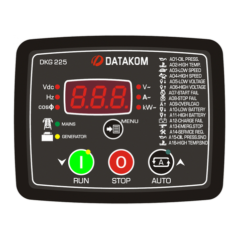
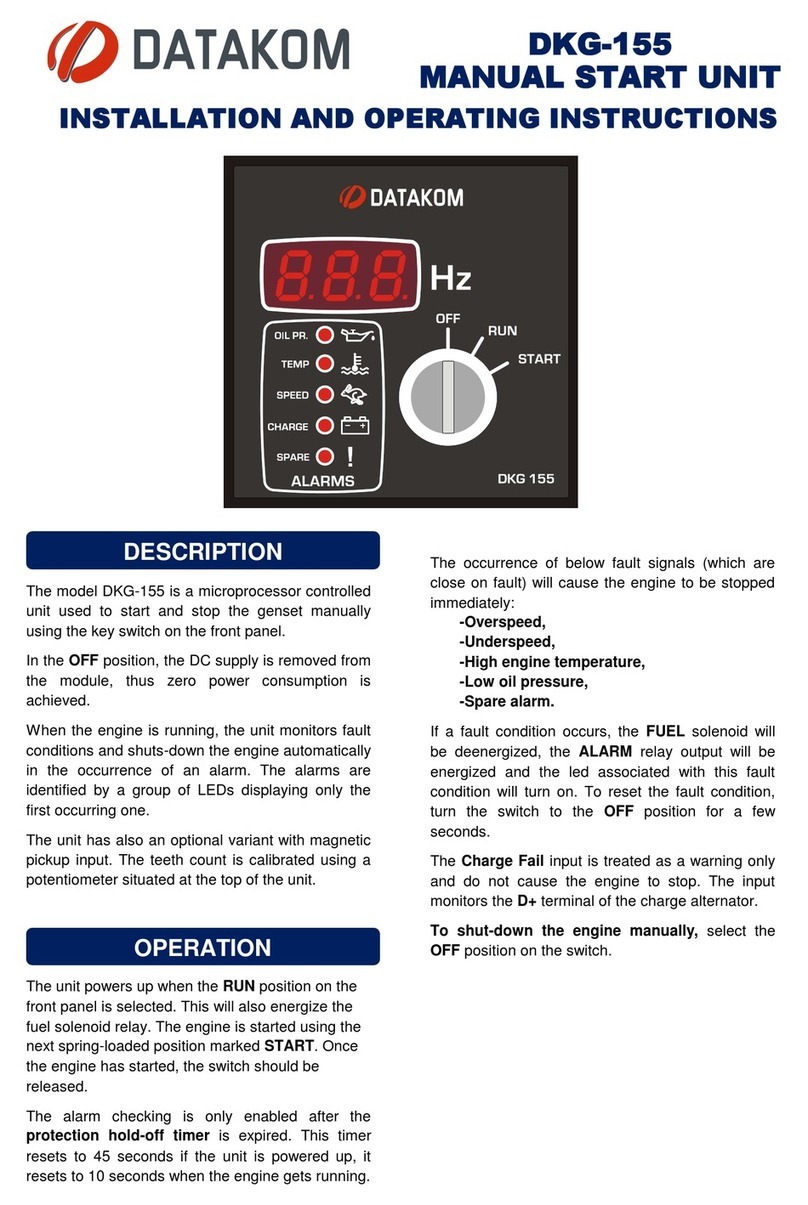
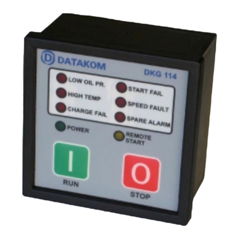
  9. Datakom DKG-225 User manual

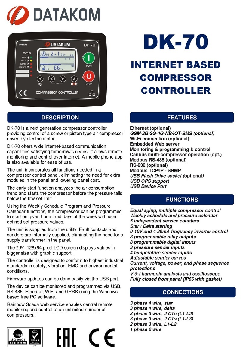
Datakom DKG-225 User manual

DKG-225, is a low cost AMF controller for 12V-DC
gensets, featuring an internal battery charger. Internal
fuel and crank relays are rated at 40Amps@12V-DC
and do not require external relays.
Thus a typical transfer panel will simply consist on
one DKG-225 and two contactors, reducing material
cost, panel size and production time.
The unit supports also current transformer
connections allowing detailed power measurements
from both mains and genset sides. The standard unit
supports 1A and 5A secondary CTs. A special version
supports low cost and small 0.1A secondary CTs
allowing more compact panel design.
The 1Amp @12V-DC rated battery charger is
sufficient for the float charging of the engine start
battery.
Electrical equipment should be installed only by
qualified specialist. No responsibility is assured by
the manufacturer or any of its subsidiaries for any
consequences resulting from the non-compliance to
these instructions.
Check the unit for cracks and damages due to
transportation. Do not install damaged equipment.
Do not open the unit. There is no serviceable parts
inside.
Fuses of fast type with a maximum rating of 6A
must be connected to phase voltage inputs in close
proximity of the unit.
Disconnect all power before working on equipment.
When the unit is connected to the network do not
touch terminals.
Any electrical parameter applied to the device must
be in the range specified in the user manual. Values
exceeding limits may shorten device life, destroy its
precision or damage it.
Do not try to clean the device with solvent or the
like. Only clean with a dump cloth.
Do not allow water to come in the unit.
Verify correct terminal connections before applying
power.
Only for front panel mounting.
Before installation:
Read the user manual carefully, determine the
correct connection diagram.
Remove all connectors and mounting brackets from
the unit, then pass the unit through the mounting
opening.
Put mounting brackets and tighten. Do not tighten
too much, this can brake the enclosure.
Make electrical connections with plugs removed
from sockets, then place plugs to their sockets.
Make sure that the ambient temperature does not
exceed the maximum operating temperature limit.
During Installation:
Cables should be compatible with the operating
temperature range. Use adequate cable section, at
least 0.75mm2 (AWG18).
Below conditions may damage the device:
Incorrect connections.
Incorrect battery voltage.
Reverse battery voltage
Voltage at terminals beyond specified range.
Voltage applied to digital inputs over specified
range.
Current at terminals beyond specified range.
Overload or short circuit at relay outputs.
Excessive vibration, installation on vibrating parts.
Below conditions may cause abnormal operation:
Battery voltage below minimum acceptable level.
Frequency out of specified limits
Missing grounding.
Make electrical connections with
plugs removed from sockets,
otherwise the unit may get
damaged.
Engine body must be grounded for
the correct operation of the unit.
Otherwise faulty voltage and
frequency measurements may
occur.
Do not install the unit close to
high electromagnetic noise
emitting devices like contactors,
high current busbars, switchmode
power supplies and the like.
DKG-225
GENSET CONTROL & ATS PANEL
INSTALLATION GUIDE
Current Transformers must be
used for current measurement.
No direct connection allowed.
INSTALLATION
SAFETY NOTICE
Failure to follow below
instructions may result in
death or serious injury
SAFETY FIRST !
Alternator Voltage: 0-300 V-AC (Phase-Neutral)
Alternator Frequency: 0-100 Hz.
Mains Voltage: 0-300 V-AC (Phase-Neutral)
Mains Frequency: 0-100 Hz.
Topology: 1 or 3 phases with neutral
Cranking Dropouts: survives 0V for 100ms.
Fuel and Crank Relay Outputs: 40 A / 12V-DC
Alarm Relay Output: 10A / 12 V-DC
MC and GC Relay Outputs: 16A / 250 V-AC
Charge Excitation: min 2 W.
Battery Charge Current: min 1A / 13.7V-DC (195-
300V-AC)
Current Inputs: CT inputs xxx/5A (opt xxx/0.1A)
Analog Input Range: 0-5000 ohms
Digital Inputs: 0 to 36V-DC
Operating temp.: -40°C (-40°F) to 70°C (158°F).
Storage temp.: -55°C (-67°F) to 80°C (176°F).
Maximum humidity: 95% non-condensing.
Dimensions: 133x 107 x 46 mm (WxHxD)
Panel Cutout: 117 x 87mm minimum.
Weight: 200 g (approx..)
Enclosure: Flame retardant, high temp ABS/PC (UL94-
V0)
IP Protection: IP65 (front with gasket), IP30 (rear)
EU Directives Conformity
-2006/95/EC (low voltage)
-2004/108/EC (electro-magnetic compatibility)
Reference standards for EU Conformity:
-EN 61010 (safety)
-EN 61326 (EMC)
INSTALLATION DIAGRAM
TECHNICAL SPECIFICATIONS
BUTTON
FUNCTION
Genset runs off load.
If the mains fail, then the genset runs
and takes the load.
Genset stops.
If held pressed during 10 seconds,
resets service counters.
Selects next display value. If held
pressed then selects first LAMP TEST
the programming mode.
If these two buttons are held pressed
for 5 seconds, enters the special
programming mode where high
priority parameters are also
programmable.
SERVICE RESET:
To turn off the SERVICE REQUEST led, and reset the
service period, press the STOP key for 10 seconds.
When “Srv” is displayed, service timers are reset and
the service request is erased.
MODE LEDS: Turns on when related mode is
selected on the unit.
STOP: In this mode, if mains phase voltages are
within the programmed limits then the mains contactor
will be energized. The engine does not run.
AUTO: If at least one of the mains phase voltages is
outside limits, the mains contactor will be deactivated.
The engine will run. When alternator phase voltages
and frequency are within limits, then the generator
contactor will be energized.
When all the mains phase voltages are within the
limits, the generator contactor is deactivated and the
mains contactor will be energized and the diesel will
stop. The unit will be ready for the next mains failure.
RUN: The operation of the generator is similar to the
AUTO mode, but the mains contactor will not be
deactivated and the genset will run off load.
MAINS AND GENSET LEDS:
MAINS: If mains phase voltages and frequency is
within limits then this led flashes. When the load is
on mains, this led turns on steady.
GENSET:If genset phase voltages and frequency is
within limits then this led flashes. When the load is
on genset, this led turns on steady.
PUSHBUTTON FUNCTIONS
RUN mode
button
STOP mode
button
AUTO mode
button
Menu
selection
button
Display unit
leds
Display unit
leds
Mains led.
Flashes when
mains is OK,
turns-on steady
when load is fed
by mains.
Genset led.
Flashes when
genset is
running, turns-on
steady when
load is fed by the
genset.
Programming mode is used to adjust delays, operating
limits and configuration of the unit.
In order to enter the program mode please hold
pressed the MENU button for 10 seconds.
In program mode, when the MENU pushbutton is
depressed, the display shows the program number.
When MENU pushbuttopn is released the program
parameter value is displayed.
Entering the program mode does not affect genset
operation. If mains fail during programming, then the
genset will automatically run and take the load.
Program parameters may be scrolled with MENU
button. If the pushbutton is held pressed then the
parameter number increases faster.
Parameter value is increased/decreased with RUN
(▼) and AUTO(▲) pushbuttons. If the pushbutton is
held pressed then the parameter value
increases/decreases faster.
When the program parameter is modified, it is
automatically saved in a non-volatile memory.
In order to exit program mode, press the STOP button.
If no button is pressed during 1 minute, the unit will
automatically exit the program mode.
Program parameters are divided in two groups being
low and high priority parameters. If the program mode is
entered bypressing the MENU button, only low priority
parameters are displayed. In order to display high
priority parameters, enter the program mode by holding
pressed both MENU and STOP buttons.
PGM
Parameter Name
Unit
Std.
Description
P_00
Current Transformer Ratio
A
50
All transformers must have the same rating.
The secondary of the transformer will be 5 Amps.
P_01
Fuel output type
-
0
0: activate to start 1: activate to stop
P_02
Oil switch type
-
0
0: oil pressure switch 1: oil level switch
P_03
Single phase operation
-
0
0: tri phased 1: single phased
P_04
Overcurrent limit
A
0
If the current goes above this limit, during the period
defined in Overload Timeout then a Overcurrent Load
Dump alarm will be generated.
If this parameter is 0 then Overcurrent check is disabled.
P_05
Excess power limit
kW
0
If the active power goes above this limit, during the
period defined in Overload Timeout then an Excess
Power Load Dump alarm will be generated.
If this parameter is 0 then Excess Power check is
disabled.
P_06
Overcurrent/ Excess
Power / Frequency /
Voltage delay timer
sec
5
This is the period between OVERCURRENT or EXCESS
POWER or VOLTAGE or FREQUENCY limits are
exceeded and the related alarm occurs.
P_07
Preheat timer
Sec
1
This is the time after the fuel solenoid is energized and
before the genset is started. During this period the
PREHEAT relay function is active.
P_08
Choke timer
Sec
5
This is the control delay of CHOKE output.
The choke output is activated together with the crank
output. It is released after this delay or when engine
runs, whichever occurs first.
P_09
Engine heating timer
Sec
4
This is the period used for engine heating before
genset takes the load.
P_10
Stop timer
Sec
10
This is the maximum time duration for the engine to
stop. During this period the STOP relay function is
active. If the genset has not stopped after this period, a
FAIL TO STOP warning occurs.
P_11
Mains waiting timer
Min
0.5
This is the time between the mains voltages entered
within the limits and the generator contactor is
deactivated.
P_12
Cooldown timer
min
1.0
This is the period that the generator runs for cooling
purpose after the load is transferred to mains.
P_13
Mains voltage low limit
V
170
If one of the mains phases goes under this limit, it
means that the mains are off and it starts the transfer
to the genset in AUTO mode.
P_14
Mains voltage high limit
V
270
If one of the mains phases goes over this limit, it
means that the mains are off and it starts the transfer
to the genset in AUTO mode.
PROGRAMMING
Following parameters are in the “high priority” group.

Other manuals for DKG-225

1

Other Datakom Controllers manuals

Datakom DK-70 User manual

Datakom

Datakom DK-70 User manual

Datakom D-300 MK2 User manual

Datakom

Datakom D-300 MK2 User manual

Datakom DKG-329 User manual

Datakom

Datakom DKG-329 User manual

Datakom DKG-325 User manual

Datakom

Datakom DKG-325 User manual

Datakom D Series User manual

Datakom

Datakom D Series User manual

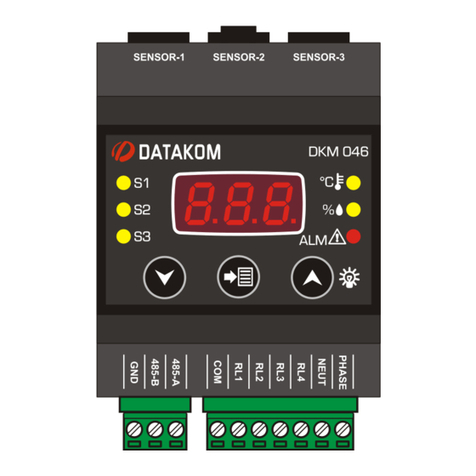
Datakom DKM-046 User manual

Datakom

Datakom DKM-046 User manual

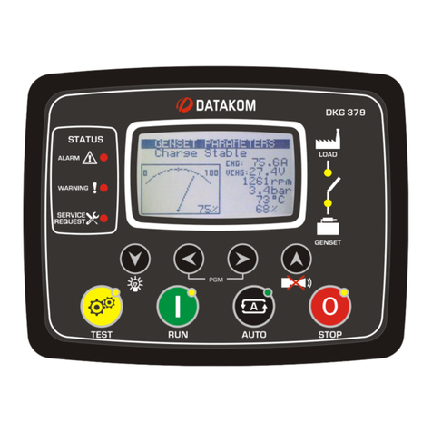
Datakom DKG-379 User manual

Datakom

Datakom DKG-379 User manual

Datakom DKG-225 User manual

Datakom

Datakom DKG-225 User manual

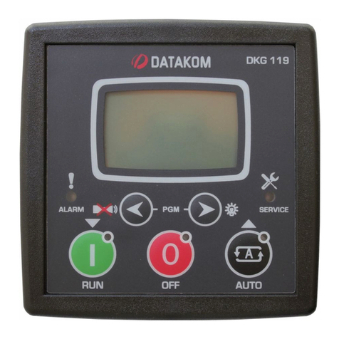
Datakom DKG-119 User manual

Datakom

Datakom DKG-119 User manual

Datakom D-500 MK2 User manual

Datakom

Datakom D-500 MK2 User manual

Datakom D-100 MK2 User manual

Datakom

Datakom D-100 MK2 User manual

Datakom DKG-109 User manual

Datakom

Datakom DKG-109 User manual

Datakom DK-45 User manual

Datakom

Datakom DK-45 User manual

Datakom DKG-108 User manual

Datakom

Datakom DKG-108 User manual

Datakom DK-45 MK2 User manual

Datakom

Datakom DK-45 MK2 User manual

Datakom DKG-255 User manual

Datakom

Datakom DKG-255 User manual

Datakom D-500 User manual

Datakom

Datakom D-500 User manual

Datakom DKG-116 User manual

Datakom

Datakom DKG-116 User manual

Datakom D-500 MK3 User manual

Datakom

Datakom D-500 MK3 User manual

Datakom DK-40 User manual

Datakom

Datakom DK-40 User manual

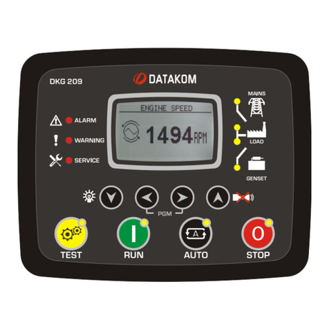
Datakom DKG-209 User manual

Datakom

Datakom DKG-209 User manual

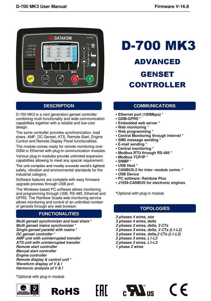
Datakom D-700 MK3 User manual

Datakom

Datakom D-700 MK3 User manual

Datakom DKG-155 User manual

Datakom

Datakom DKG-155 User manual

Datakom DKG-114 Manual

Datakom

Datakom DKG-114 Manual

Popular Controllers manuals by other brands

dixell EMERSON XR70C Installing and operating instructions

dixell

dixell EMERSON XR70C Installing and operating instructions

Warner Electric slo-syn 440 installation instructions

Warner Electric

Warner Electric slo-syn 440 installation instructions

Watts WFC-03 10Z HC RF 24 Quick installation guide

Watts

Watts WFC-03 10Z HC RF 24 Quick installation guide

intelliConsole IC200 quick start guide

intelliConsole

intelliConsole IC200 quick start guide

TimeTec Security BLE-16 installation guide

TimeTec Security

TimeTec Security BLE-16 installation guide

Minarik MAC Series user manual

Minarik

Minarik MAC Series user manual

HomeMatic HM-LC-BI1PBU-FM Installation and operating manual

HomeMatic

HomeMatic HM-LC-BI1PBU-FM Installation and operating manual

Danfoss VLT HVAC Basic Drive FC 101 quick guide

Danfoss

Danfoss VLT HVAC Basic Drive FC 101 quick guide

Full Gauge Controls MT-543Ri plus quick start guide

Full Gauge Controls

Full Gauge Controls MT-543Ri plus quick start guide

Redarc Tow-Pro Elite manual

Redarc

Redarc Tow-Pro Elite manual

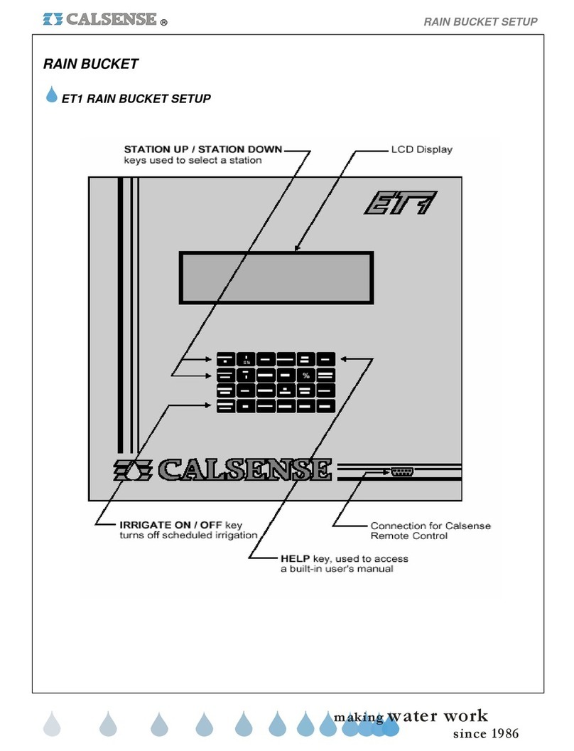
Calsense ET1 Setup guide

Calsense

Calsense ET1 Setup guide

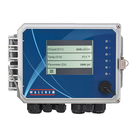
Walchem W600 Series instruction manual

Walchem

Walchem W600 Series instruction manual

Envirosight VISIONCONTROL VC500 user manual

Envirosight

Envirosight VISIONCONTROL VC500 user manual

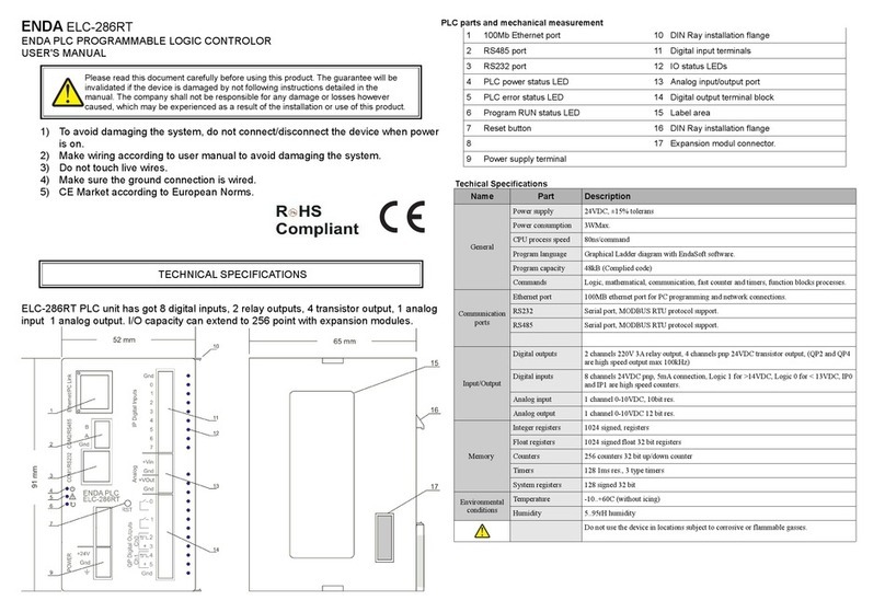
ENDA ELC-286RT user manual

ENDA

ENDA ELC-286RT user manual

Rosslare AC-225? AC-225IP? AC-225U Installation and user guide

Rosslare

Rosslare AC-225? AC-225IP? AC-225U Installation and user guide

LG G3L-PUEA user manual

LG

LG G3L-PUEA user manual

DMX4ALL ArtNet Player X4 Application note

DMX4ALL

DMX4ALL ArtNet Player X4 Application note

Lionel TMCC manual

Lionel

Lionel TMCC manual

manuals.online logo
manuals.online logoBrands
  • About & Mission
  • Contact us
  • Privacy Policy
  • Terms and Conditions

Copyright 2025 Manuals.Online. All Rights Reserved.