McConnel SEEDAERATOR User manual

Publication 740
March 2014
Part No. 22675.40
Revised: 24.07.15 SEEDAERATOR
Linkage Mounted Seed Drill
For use in conjunction with the Artemis Lite Controls Manual (Publication 741)
Operator Manual

IMPORTANT
VERIFICATION OF WARRANTY REGISTRATION
DEALER WARRANTY INFORMATION & REGISTRATION VERIFICATION
It is imperative that the selling dealer registers this machine with McConnel Limited before
delivery to the end user – failure to do so may affect the validity of the machine warranty.
To register machines go to the McConnel Limited web site at www.mcconnel.com, log
onto ‘Dealer Inside’ and select the ‘Machine Registration button’which can be found in
the Service Section of the site. Confirm to the customer that the machine has been
registered in the section below.
Should you experience any problems registering a machine in this manner please contact
the McConnel Service Department on 01584 875848.
Registration Verification
Dealer Name:
……………………..…………………………………………………………….
Dealer Address:
…….………………………………………………………………………….
Customer Name:
……………………..…………………………………………………………
Date of Warranty Registration:
……/……/...…… Dealer Signature: ………………..……
NOTE TO CUSTOMER / OWNER
Please ensure that the above section above has been completed and signed by the selling
dealer to verify that your machine has been registered with McConnel Limited.
IMPORTANT: During the initial ‘bedding in’ period of a new machine it is the customer’s responsibility
to regularly inspect all nuts, bolts and hose connections for tightness and re-tighten if required. New
hydraulic connections occasionally weep small amounts of oil as the seals and joints settle in – where
this occurs it can be cured by re-tightening the connection – refer to torque settings chart below.The
tasks stated above should be performed on an hourly basis during the first day of work and at least
daily thereafter as part of the machines general maintenance procedure.
CAUTION: DO NOT OVER TORQUE HYDRAULIC FITTINGS AND HOSES
TORQUE SETTINGS FOR HYDRAULIC FITTINGS
HYDRAULIC HOSE ENDS PORT ADAPTORS WITH BONDED SEALS
BSP
Setting
Metric
BSP
Setting
Metric
1/4” 18 Nm 19 mm 1/4” 34 Nm
19 mm
3/8” 31 Nm 22 mm 3/8” 47 Nm
22 mm
1/2” 49 Nm 27 mm 1/2” 102 Nm
27 mm
5/8” 60 Nm 30 mm 5/8” 122 Nm
30 mm
3/4” 80 Nm 32 mm 3/4” 149 Nm
32 mm
1” 125 Nm 41 mm 1” 203 Nm
41 mm
1.1/4”
190 Nm
50 mm
1.1/4”
305 Nm
50 mm
1.1/2” 250 Nm 55 mm 1.1/2” 305 Nm
55 mm
2” 420 Nm 70 mm 2” 400 Nm
70 mm


Warranty Policy (page 1 of 3)
WARRANTY POLICY
WARRANTY REGISTRATION
All machines must be registered, by the selling dealer with McConnel Ltd, before delivery to the end user.
On receipt of the goods it is the buyer’s responsibility to check that the Verification of Warranty
Registration in the Operator’s Manual has been completed by the selling dealer.
1. LIMITED WARRANTIES
1.01. All mounted machines supplied by McConnel Ltd are warranted to be free from defects in material
and workmanship from the date of sale to the original purchaser for a period of 12 months, unless a
different period is specified.
All Self Propelled Machines supplied by McConnel Ltd are warranted to be free from defects in
material and workmanship from the date of sale to the original purchaser for a period of 12 months
or 1500 hours. Engine warranty will be specific to the Manufacturer of that unit.
1.02. All spare parts supplied by McConnel Ltd and purchased by the end user are warranted to be free from
defects in material and workmanship from the date of sale to the original purchaser for a period of 6
months. All parts warranty claims must be supported by a copy of the failed part invoice to the end
user. We cannot consider claims for which sales invoices are not available.
1.03. The warranty offered by McConnel Ltd is limited to the making good by repair or replacement for the
purchaser any part or parts found, upon examination at its factory, to be defective under normal use
and service due to defects in material or workmanship. Returned parts must be complete and
unexamined. Pack the component(s) carefully so that any transit damage is avoided. All ports on
hydraulic items should be drained of oil and securely plugged to prevent seepage and foreign body
ingress. Certain other components, electrical items for example, may require particular care when
packing to avoid damage in transit.
1.04. This warranty does not extend to any product from which McConnel Ltd’s serial number plate has
been removed or altered.
1.05. The warranty policy is valid for machines registered in line with the terms and conditions detailed and
on the basis that the machines do not extend a period of 24 months or greater since their original
purchase date, that is the original invoice date from McConnel Limited.
Machines that are held in stock for more than 24 months cannot be registered for warranty.
1.06. This warranty does not apply to any part of the goods, which has been subjected to improper or
abnormal use, negligence, alteration, modification, fitment of non-genuine parts, accident damage,
or damage resulting from contact with overhead power lines, damage caused by foreign objects (e.g.
stones, iron, material other than vegetation), failure due to lack of maintenance, use of incorrect oil or
lubricants, contamination of the oil, or which has served its normal life. This warranty does not apply
to any expendable items such as blades, belts, clutch linings, filter elements, flails, flap kits, skids, soil
engaging parts, shields, guards, wear pads, pneumatic tyres or tracks.
1.07. Temporary repairs and consequential loss - i.e. oil, downtime and associated parts are specifically
excluded from the warranty.
1.08. Warranty on hoses is limited to 12 months and does not include hoses which have suffered external
damage. Only complete hoses may be returned under warranty, any which have been cut or repaired
will be rejected.
1.09. Machines must be repaired immediately a problem arises. Continued use of the machine after a
problem has occurred can result in further component failures, for which McConnel Ltd cannot be held
liable, and may have safety implications.
1.10. If in exceptional circumstances a non McConnel Ltd part is used to effect a repair, warranty
reimbursement will be at no more than McConnel Ltd’s standard dealer cost for the genuine part.

Warranty Policy (page 2 of 3)
1.11. Except as provided herein, no employee, agent, dealer or other person is authorised to give any
warranties of any nature on behalf of McConnel Ltd.
1.12. For machine warranty periods in excess of 12 months the following additional exclusions shall apply:
1.12.1. Hoses, exposed pipes and hydraulic tank breathers.
1.12.2. Filters.
1.12.3. Rubber mountings.
1.12.4. External electric wiring.
1.12.5. Bearings and seals
1.12.6. External Cables, Linkages
1.12.7. Loose/Corroded Connections, Light Units, LED’s
1.12.8. Comfort items such as Operator Seat, Ventilation, Audio Equipment
1.13. All service work, particularly filter changes, must be carried out in accordance with the manufacturer’s
service schedule. Failure to comply will invalidate the warranty. In the event of a claim, proof of the
service work being carried out may be required.
1.14. Repeat or additional repairs resulting from incorrect diagnosis or poor quality previous repair work
are excluded from warranty.
NB Warranty cover will be invalid if any non-genuine parts have been fitted or used. Use of non-genuine
parts may seriously affect the machine’s performance and safety. McConnel Ltd cannot be held
responsible for any failures or safety implications that arise due to the use of non-genuine parts.
2. REMEDIES AND PROCEDURES
2.01. The warranty is not effective unless the Selling Dealer registers the machine, via the McConnel web
site and confirms the registration to the purchaser by completing the confirmation form in the
operator’s manual.
2.02. Any fault must be reported to an authorised McConnel Ltd dealer as soon as it occurs. Continued use
of a machine, after a fault has occurred, can result in further component failure for which McConnel
Ltd cannot be held liable.
2.03. Repairs should be undertaken within two days of the failure. Claims submitted for repairs undertaken
more than 2 weeks after a failure has occurred, or 2 days after the parts were supplied will be
rejected, unless the delay has been authorised by McConnel Ltd. Please note that failure by the
customer to release the machine for repair will not be accepted as a reason for delay in repair or
submitting warranty claims.
2.04. All claims must be submitted, by an authorised McConnel Ltd Service Dealer, within 30 days of the
date of repair.
2.05. Following examination of the claim and parts, McConnel Ltd will pay, at their discretion, for any valid
claim the invoiced cost of any parts supplied by McConnel Ltd and appropriate labour and mileage
allowances if applicable.
2.06. The submission of a claim is not a guarantee of payment.
2.07. Any decision reached by McConnel Ltd. is final.
3. LIMITATION OF LIABILITY
3.01. McConnel Ltd disclaims any express (except as set forth herein) and implied warranties with respect to
the goods including, but not limited to, merchantability and fitness for a particular purpose.
3.02. McConnel Ltd makes no warranty as to the design, capability, capacity or suitability for use of the
goods.
3.03. Except as provided herein, McConnel Ltd shall have no liability or responsibility to the purchaser or
any other person or entity with respect to any liability, loss, or damage caused or alleged to be caused
directly or indirectly by the goods including, but not limited to, any indirect, special, consequential, or
incidental damages resulting from the use or operation of the goods or any breach of this warranty.
Notwithstanding the above limitations and warranties, the manufacturer’s liability hereunder for
damages incurred by the purchaser or others shall not exceed the price of the goods.
3.04. No action arising out of any claimed breach of this warranty or transactions under this warranty may
be brought more than one (1) year after the cause of the action has occurred.

Warranty Policy (page 3 of 3)
4. MISCELLANEOUS
4.01. McConnel Ltd may waive compliance with any of the terms of this limited warranty, but no waiver of
any terms shall be deemed to be a waiver of any other term.
4.02. If any provision of this limited warranty shall violate any applicable law and is held to be
unenforceable, then the invalidity of such provision shall not invalidate any other provisions herein.
4.03. Applicable law may provide rights and benefits to the purchaser in addition to those provided herein.
McConnel Limited

DECLARATION OF CONFORMITY
Conforming to EU Machinery Directive 2006/42/EC
We,
McCONNEL LIMITED, Temeside Works, Ludlow, Shropshire SY8 1JL, UK
Hereby declare that:
The Product; Tractor Mounted Seed Drill
Product Code; DRIL
Serial No. & Date ………………………………… Type …………………………
Manufactured in; United Kingdom
Complies with the required provisions of the Machinery Directive 2006/42/EC
The machinery directive is supported by the following harmonized standards;
■BS EN ISO 12100 (2010) Safety of machinery –General principles for design –Risk
assessment and risk reduction.
■BS EN 349 (1993) + A1 (2008) Safety of machinery - Minimum distances to avoid the
entrapment with human body parts.
■BS EN ISO 14120 (2015) Safety of machinery - Guards general requirements for the
design and construction of fixed and movable guards.
■BS EN 4413 (2010) Hydraulic fluid power. Safety requirements for systems and their
components.
McCONNEL LIMITED operates an ISO 9001:2008 quality management system,
certificate number: FM25970.
This system is continually assessed by the;
British Standards Institution (BSI), Beech House, Milton Keynes, MK14 6ES, UK
BSI is accredited by UK Accreditation Service, accreditation number: UKAS 003.
The EC declaration only applies if the machine stated above is used in
accordance with the operating instructions.
Signed …………………................ Responsible Person
CHRISTIAN DAVIES on behalf of McCONNEL LIMITED
Status: General Manager Date: January 2018

For Safety and Performance…
ALWAYS READ THE BOOK FIRST
- NOISE STATEMENT -
The equivalent daily personal noise exposure from this machine measured at the operators’ ear is
within the range 78 –85 dB, these figures apply to a normal distribution of use where the noise
fluctuates between zero and maximum. The figures assume that the machine is fitted to a tractor with
a ‘quiet’ cab with the windows closed in a generally open environment. We recommend that the
windows are kept closed. With the cab rear window open the equivalent daily personal noise
exposure will increase to a figure within the range 82 –88 dB. At an equivalent daily noise exposure
level of 85 –90 dB ear protection is recommended and must always be used if any window is left
open.
Operating, servicing and maintaining this equipment can
expose you to chemicals including gasoline, diesel fuel,
lubricants, petroleum products, engine exhaust, carbon
monoxide, and phthalates, which are known to the State of
California to cause cancer and birth defects or other
reproductive harm. To minimize exposure, avoid breathing exhaust, do not idle the engine except as
necessary, service your vehicle in a well-ventilated area and wear gloves or wash your hands
frequently when servicing your vehicle. Battery posts, terminals and related accessories contain lead
and lead compounds, chemicals known to the state of California to cause cancer, birth defects or
other reproductive harm. For more information go to www.P65Warnings.ca.gov. This website,
operated by California's Office of Environmental Health Hazard Assessment, provides information
about these chemicals and how individuals may be exposed to them.
McCONNEL LIMITED
Temeside Works
Ludlow
Shropshire
England
Telephone: +44 (0)1584 873131
www.mcconnel.com


1
LIST OF CONTENTS
General Information 2
Features 3
Introduction 4
Technical data 5
Component Identification 6
Safety Information 7
Safety Decals 8
Tractor Requirements 8
Machine Attachment 9
Auto-Reset Leg Supports 10
Auto-Reset Leg Charging Procedure 10
Stand Legs 11
Levelling the Machine 12
Hopper Access Platform 13
Hopper & Hopper Extension Kit 14
Sensor Switch 15
Radar Sensor 16
Leading Tine Legs 17
Wheels, Tyres & Scrapers 21
Seed Coulters 22
Press Wheels 23
Bout Markers 24
Rear Harrow 27
Blower Fan 28
Seed Distribution System 29
Drop Box 30
Metering Unit 31
Metering Unit Calibration 31
Operation 33
Maintenance & Storage 34

2
GENERAL INFORMATION
Read this manual before fitting or operating the machine. Whenever any doubt exists
contact your dealer or the McConnel Service Department for assistance.
Use only ‘McConnel Genuine Parts’ on McConnel equipment and machinery
DEFINITIONS - The following definitions apply throughout this manual:
WARNING:
An operating procedure, technique etc., which –
can result in personal injury or loss of life if not observed carefully.
CAUTION:
An operating procedure, technique etc., which –
can result in damage to either machine or equipment if not observed carefully.
NOTE:
An operating procedure, technique etc., which is –
considered essential to emphasise.
LEFT AND RIGHT HAND:
These terms are applicable to the machine when it is viewed from the rear facing forwards.
Note: The illustrations in this manual are for instructional purposes only and may on occasion not
show some components in their entirety. In some instances an illustration may appear slightly
different to that of your particular model but the general procedure will be the same. E&OE.
Machine & Dealer Information
Record the Serial Number of your machine on this page and always quote this number when
ordering parts. Whenever information concerning the machine is requested remember also to state
the make and model of tractor to which the machine is fitted.
Machine Serial Number: Installation Date:
Machine Model details:
Dealer Name:
Dealer Address:
Dealer Telephone No:
Dealer Email Address:

3
FEATURES
Seedaerator
3-point Linkage Mounted
3.0M Working Width
9 Sowing Bands
‘A’ Share Tine Coulters (175mm Sowing Band Width)
Depth Adjustable Leading Tines (100 - 300mm)
Tines Safety Break-back System
Large Diameter Consolidating Wheels with Pneumatic Tyres
Incremental Depth Adjustable Tine Coulters with Safety Break-back System
Pressure Adjustable Rear Press Wheels
850 Litre Hopper
Large Capacity Hopper Extension (Option)
Rear lighting kit

4
INTRODUCTION
Machine Description & Purpose of Use
The McConnel Seedaerator is a high performance Strip Till Drill specifically designed to
deliver single pass drilling straight into previous crop residues saving time, money and fuel
costs while maintaining crop yields in even the most challenging weather and soil
conditions.
The machine provides cultivation and drilling of the land in strips ensuring the adjoining
soil structure is left undisturbed with crop residues remaining on the surface to decay so
nutrients can be released back into the ground to create a living biotic soil with high levels
of organic activity improving soil quality, aeration, water percolation and moisture retention,
thus creating the perfect environment for crop growth.
The Seedaerator has been developed for both farmers and contractors who are looking to
reap the benefits of strip till drilling with improved soil structure, lower operating costs to
deliver sustainable intensive farming without damaging the environment.
Key Benefits
Improves soil structure
Improves organic activity
Increases nitrogen release
Improves drainage and moisture retention
Dramatically reduces compaction levels
Reduces labour & fuel costs

5
Machine Identification Plate
TECHNICAL DATA
Machine Specifications
Working Width 3.0m
Mounting Type 3-point linkage
Number of Seed Bands / Spacing 9 bands / 333mm spacing
Leading Leg Options Winged Point or Low Disturbance
Leading Leg Working Depth 100 – 300mm in 50mm increments (*)
Large Diameter Press Wheels Standard
Seed Coulter Option Standard, Double Shot or Bean
Seed Coulter Working Depth 25 – 150mm in 12mm increments
Rear Press Wheels Standard
Rear Harrow Standard or Paddle Board option
Hopper Capacity 600kg or 1200kg
Controls RDS Artemis Lite
Variable Seed Rate Standard
Marker Arms Standard
Machine Weight (dependant on build) 2500 - 3000kg
Minimum Tractor Requirement 160HP
(*) Recommended maximum working depth for Low Disturbance Legs is 150mm
Machine Identification
Each machine is fitted with an identification plate that will include the following information:
1. Machine Part Number
2. Machine Serial No.
3. Machine Weight
When ordering spares or replacement parts from your
local dealer it is important to quote both Part Number
and Serial Number as stated on the identification
plate so the machine and model can be quickly and
correctly identified.
Noise Level
The sound level of this machine, as measured at the operator’s ear, is within the range of
70 to 90 dB when the rear window of the tractor is open. We recommend that ear
protectors are worn and the tractor windows kept closed at all times when operating this
machine.

6
MAIN COMPONENTS - LOCATION & IDENTIFICATION
A. Main Frame
B. Hopper
C. Access Platform
D. Safety Rail
E. Platform Ladder (Stowed)
F. Support Legs (Stowed)
G. Bout Marker Arm
H. Bout Marker Ram
I. Bout Marker
J. Bout Marker Support Wheel
K. Hydraulic Fan
L. Seed Distribution Head
M. Seed Pipes
N. Seed Coulter (Adjustable)
O. Rear Press Wheel
P. Press Wheel Adjuster
Q. Levelling Harrow
R. Cultivation Leg
S. Press Wheel
T. Road Lighting Kit
Front View
Rear View

7
SAFETY SECTION
This machine has the potential to be extremely dangerous, it is therefore imperative that
both owner and operator of the machine reads and understands the following section to
ensure they are fully aware of the dangers that do, or may exist, and their responsibilities
surrounding the use and operation of the machine.
When the machine is not in use it should be lowered to rest on the ground. In the event of
any fault being detected with the machine’s operation it must be stopped immediately and
not used again until the fault has been corrected by a qualified technician.
▲ALWAYS ensure all operators have read and understood the operation and safety
information in the manual before using the machine.
▲ALWAYS inspect the work area for possible dangers or risks before starting work.
▲ALWAYS ensure all machine guards are in place and are kept in good condition – they
are there for your protection and the safety of others.
▲ALWAYS keep clear of any moving or rotating components.
▲ALWAYS stop a working machine when other people enter a work area and only
restart when the area is clear of any risk.
▲ALWAYS be alert – if any help is being given during the coupling or uncoupling of
machines or any other equipment ensure the assistant is kept clear of risk of
entrapment.
▲NEVER wear loose or flapping clothing near a working machine.
▲NEVER permit anyone to ride on the machine, whether in transport or in work.
▲NEVER approach a working machine or attempt any kind of maintenance on a working
machine.
▲NEVER work under a machine that is unsupported or raised on the tractors hydraulic
lift – always use suitable substantial supports placed under the machine on a firm level
work area.
▲NEVER allow bystanders near a working machine – ensure they remain at a safe
distance from the machine.
▲NEVER permit children to play on a machine even when removed from the tractor and
stored.
8
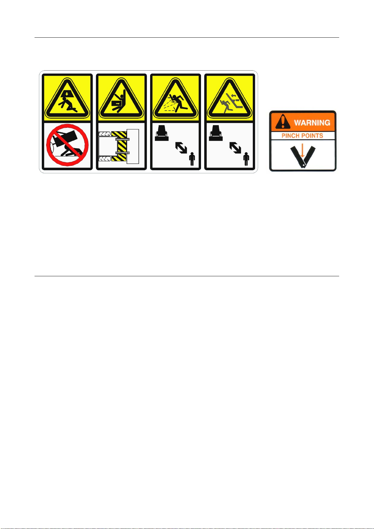
SAFETY DECALS
The following safety decals are displayed on the machine; these decals should be kept in
a readable condition at all times and replaced immediately if damaged or missing.
1. DANGER - Unsupported Machine Danger.
2. DANGER - Keep Out Zone.
3. DANGER - Thrown Debris Risk.
4. DANGER – Falling Wing Danger.
5. DANGER – Pinch Point Risk.
TRACTOR REQUIREMENTS
Tractor Power Requirements
It is impossible to give any hard and fast figures on horsepower requirements as
ground conditions can vary enormously. Figures quoted in the specification section are
advisory only and will vary depending on local conditions and specific circumstances.
Free Flow Return
Tractors must be fitted with a Free Flow Return (minimum 3/4”).
Vehicle Ballast
It is imperative when attaching ‘third-party’ equipment to a vehicle that the maximum
possible stability of the machine and vehicle combination is retained; this can be
accomplished by the use of ballast to counter-balance the weight of the implement.
Front weights may be required in order to place 15% of total outfit weight on the front axle
for stability in transport and when turning the machine on the headland.
Tractor Linkage
It is essential that only the correct linkage arms for each particular tractor are used with the
machine. The arms have been properly matched with the horsepower of the tractor and
should be more than ‘just’ adequate. There are no features on the machine to offer
protection against the failure of unmatched, repaired, badly worn, weak or below category
tractor linkage.
Stabilisers
Check Chains and/or Stabilisers must be fitted and tightened at all times.
1. 2. 3. 4. 5.

9
MACHINE ATTACHMENT
Attachment of the machine should be performed on a safe firm level site.
Ensure all bystanders are at a safe distance from the machine and tractor.
Ballasting for Stability
It is imperative when attaching ‘third-party’ equipment to a vehicle that maximum possible
stability of the machine and vehicle combination is achieved; this can be accomplished by
the use of ‘ballast’ in order to counter-balance the weight of machine.
Depending on the size and weight of the carrying vehicle front weights may need to be
added to ensure maximum stability when transporting and/or working the machine -
contact the tractor manufacturer or local tractor dealer for advice on ballasting.
The procedure for attaching the machine is as follows;
Measure and set the tractors lower links to
identical height settings; this will ensure the
machine is mounted level (side to side) in relation
to the tractor when it is attached.
Remove linkage pins from the machines lower linkage points on
both sides of the main frame.
Slowly reverse the tractor squarely up to the machine with draft links positioned between
the lower attachment points on the main frame.
Raise or lower the draft links to a height where they are aligned with either the upper or
lower holes in the main frame attachment points; the attachment hole selected will depend
on the desired carrying height required.
Fit linkage pins and secure with linch pins.
Fit and adjust top link to place the machine in a suitable position for transportation.
Fit operator controls in the cab in a suitable location that allows for ease of operation.
Connect machine electrics to suitable connections on the tractor; refer to tractor handbook.
Remove stand legs and place them horizontally in their storage location on the machine;
refer to stand legs page for details.
With the tractor and attached machine still located on a firm level site it should now be
transversely levelled for work – refer to levelling section for details of this procedure.
Longitudinal levelling for work must be performed when the machine is at the work site in
order to suit specific task and conditions – refer to levelling section.

10
SHIPPING / STORAGE LEG SUPPORTS (Auto-Reset Models only)
Auto-reset machines are fitted with shipping/storage supports to the four front legs; these
must be removed prior to using the machine. It is recommended that the supports are
refitted for machine storage to ensure the unit is stored in a safe stable condition.
The machine must be raised and suitably supported before attempting to remove the
supports; when the supports have been removed the auto-reset system should be
pressurised as per the procedure stated below.
WARNING!
Ensure the machine is raised and suitably supported before attempting to remove
the shipping/storage leg supports.
AUTO-RESET LEG CHARGING PROCEDURE
The procedure should be performed with the auto-reset legs clear of the ground.
1. Connect the auto-reset ‘pressure’ & ‘return’ hoses to the tractor spool valve; the larger
diameter hose (3/8”) is marked ‘pressure’ and the smaller diameter hose (1/4”) is the
return.
2. Ensure tap adjacent to pressure gauge is open (refer to illustrations below for open and
closed positions). Energise tractor spool to charge the circuit with oil until the pressure
gauge shows a reading of 150 bar (+/-10 bar).
3. Close the tap when the circuit is correctly charged ensuring the gauge continues to
show a reading of 150 bar.
4. The auto-reset hoses can now be disconnected from the tractor until such time that the
circuit needs recharging. Hoses must be reconnected before any future operation of
the tap, never attempt to operate the tap with the auto-reset hoses disconnected.
CAUTION! When the auto-reset circuit is in a pressurised condition hoses must be
connected to the tractor spool valve before attempting to operate the hydraulic tap;
failure to observe this will result in a pressure build up within the hoses.
Tap open position Tap closed position

11
STAND LEGS
The machine is equipped with 2 stand legs; these are primarily for supporting the machine
when it is either ‘parked up’ or in storage.
In addition to the instances mentioned above, the machine should also be placed onto its
stand legs before attempting to make adjustments to any components or when performing
maintenance tasks.
Before resting the machine down on the stand legs they must be fitted in the correct
location on each side of the machine and secured in place with the pins and linch pins
provided - refer to illustrations below.
A firm level site capable of supporting the weight of the machine must always be selected.
For ‘parking up’ and/or storage the site should be level hard standing ground. Protect front
tines by parking them on wood blocks or planks.
Stand Leg Locations & Positions
CAUTION! Machine must always be placed to rest on its stand legs during adjustments,
maintenance, extended parking periods and at all times when it is not attached to a tractor.
Stand legs must always be secured with pins and linch pins. Park tines on wooden blocks.
Stand legs in machine support location/position. Stand legs in stowed location/position.
Table of contents


