WalkwayBollard Installation Instructions
Pg. 2
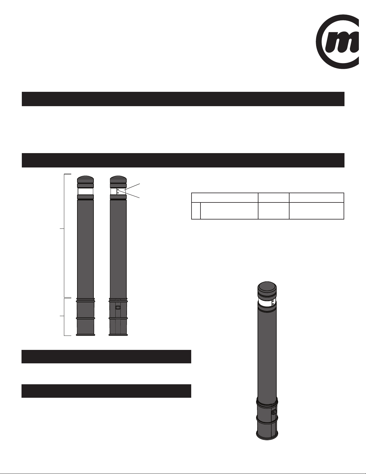
FRONT
REFLECTIVE
STRIP
BOLLARD
SLEEVE
RIVETS
BACK
FINISHED
FLOOR
LEVEL
GROUND
SAND
TOP EDGE
OF SLEEVE
FINISHED
FLOOR
LEVEL
TOP EDGE
OF SLEEVE
CONCRETE
SAND
GROUND
34 cm
[ 13.5 in ]
25 cm
[ 10 in ]
GROUND
FINISHED
FLOOR
LEVEL
GROUND
EXCAVATED
HOLE
SIDE
CUT-AWAY
TARMAC OR
CONCRETE
TARMAC OR
CONCRETE
TARMAC OR
CONCRETE
SLEEVE
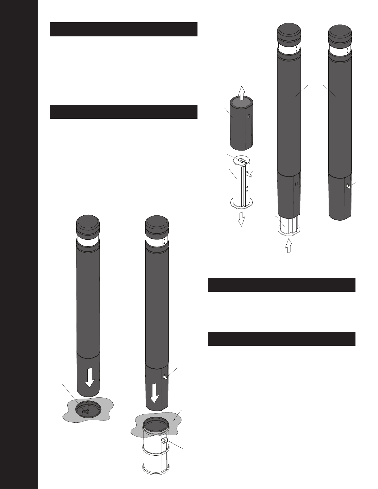
4. Apply Shell
4. Apply Shell
Excavate a hole with a diameter between 20 and 30 cm
(8 to 12 inches) and to a depth of 33 to 35 cm (13 to 14
inches) from the finished floor level. See Figure 2.
Pack the bottom of the excavated hole with layer of
sand, 2.5 to 5 cm thick (1 to 2 inches) and insert the
fully assembled WalkWay Bollard into the hole as
shown in Figure 3.
This step is critical for proper installation, DO NOT SKIP!
Ensure the top edge of the Sleeve is flush and parallel with the finished floor level by adding or removing sand. Refer
again to Figure 3. A straight edge run along the finished floor can be used to check the height of the Sleeve. Also,
check to ensure the Bollard is centered within the hole and plumb (perfectly vertical) by using a Spirit or Bubble Level.
The bollard should also be rotated so that the exposed
rivets on the Bollard’s reflective strip are facing away
from the most common line of sight. If multiple Bollards
are being installed near one another, all the rivets
should be facing the same direction.
With the WalkWay Bollard now correctly positioned and
orientated in the hole, carefully pack premixed concrete
around the perimeter. Do not allow concrete to fall in
between the Bollard and the Sleeve.
IMPORTANT: The finished concrete surface should be
flush with the top edge of the Sleeve and the finished
floor. See Figure 3.
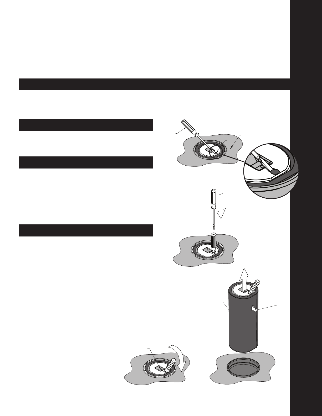
3.
4.
7.
5. IMPORTANT!
6.
8.
Clean the Bollard with a damp cloth and if necessary
use wooded supports to set the bollard over night to
avoid accidental movement before the concrete sets.
FRONT
REFLECTIVE
STRIP
BOLLARD
SLEEVE
RIVETS
BACK
FINISHED
FLOOR
LEVEL
GROUND
SAND
TOP EDGE
OF SLEEVE
FINISHED
FLOOR
LEVEL
TOP EDGE
OF SLEEVE
CONCRETE
SAND
GROUND
34 cm
[ 13.5 in ]
25 cm
[ 10 in ]
GROUND
FINISHED
FLOOR
LEVEL
GROUND
EXCAVATED
HOLE
SIDE
CUT-AWAY
TARMAC OR
CONCRETE
TARMAC OR
CONCRETE
TARMAC OR
CONCRETE
SLEEVE
Figure 2
Figure 3
Figure 3a
TOP EDGE OF
SLEEVE