Simco-Ion IQ Power User manual

IQ POWER CONTROL STATION
WITH SENSOR TECHNOLOGY
5201263 Rev D
IQ PowerTM
Control Station
with Sensor Technology
INSTALLATION AND OPERATING INSTRUCTIONS

i
IQ POWER CONTROL STATION
WITH SENSOR TECHNOLOGY
5201263 Rev D
TABLE OF CONTENTS
1. SAFETY WARNINGS .......................................................................... 1
2. DESCRIPTION .................................................................................. 3
3. SPECIFICATIONS ............................................................................... 4
4. INSTALLATION ................................................................................. 5
Mounting...............................................................................................................................5
Display Configuration ..........................................................................................................6
System Configuration...........................................................................................................6
Electrical Connections........................................................................................................17
Address / Device Number ..................................................................................................24
Set Up .................................................................................................................................27
5. OPERATION ....................................................................................28
6. MAINTENANCE ...............................................................................33
Cleaning the Control Station ..............................................................................................33
7. TROUBLESHOOTING..........................................................................34
8. PARTS AND ACCESSORIES.................................................................. 35
9. WARRANTY AND SERVICE ..................................................................37

1
IQ POWER CONTROL STATION
WITH SENSOR TECHNOLOGY
5201263 Rev D
1. SAFETY WARNINGS
PLEASE READ INSTRUCTIONS COMPLETELY BEFORE STARTING
INSTALLATION
ALL INSTALLATION AND TROUBLESHOOTING OPERATIONS MUST
BE PERFORMED BY QUALIFIED TECHNICAL PERSONNEL
This instruction manual uses symbols to identify dangerous situations as follows:
NOTE – Statements identified with NOTE indicate precautions necessary
to avoid potential equipment failure.
CAUTION – Statements identified with CAUTION indicate potential
safety hazards.
ATTENTION – Les déclarations identifiées avec ATTENTION indiquent
des dangers potentiels pour la sécurité.
WARNING – Statements identified with WARNING indicate potential
serious injury hazards.
AVERTISSEMENT – Les déclarations identifiées avec AVERTISSEMENT
indiquent un risque de blessures graves.
NOTE – This equipment must be correctly installed and properly
maintained. Adhere to the following notes for safe installation and operation:
1. Read instruction manual before installing or operating equipment.
2. Only qualified service personnel are to perform installation and repairs.
3. All equipment must be properly grounded, including the machine frame to
which the equipment is mounted.
4. Turn off input power to unit before connecting or disconnecting other
equipment.
5. Do not operate system in close proximity to flammable liquids.
6. Do not use standard Ethernet cables with IQ Power Systems.

2
IQ POWER CONTROL STATION
WITH SENSOR TECHNOLOGY
5201263 Rev D
CAUTION – Electrical Shock Hazard
Disconnect input power to high voltage power supply before connecting
or disconnecting static neutralizing bar or performing any maintenance to
the system. Avoid touching static neutralizing bar when power supply is
energized.
ATTENTION – Risque De Choc Électrique
Couper l’alimentation à l’alimentation électrique de haute tension avant de
brancher ou de débrancher la barre de neutralisation statique ou d’effectuer
un entretien au système. Évitez de toucher la barre de neutralisation statique
lorsque l’alimentation électrique est sous tension.
WARNING – Fire Hazard
Risk of explosion if battery is replaced by an incorrect type. Dispose of used
batteries according to instructions.
AVERTISSEMENT – Risque d’incendie
Risque d’explosion si la batterie est remplacée par un type incorrect. Jetez les
piles usagées conformément aux instructions.

3
IQ POWER CONTROL STATION
WITH SENSOR TECHNOLOGY
5201263 Rev D
2. DESCRIPTION
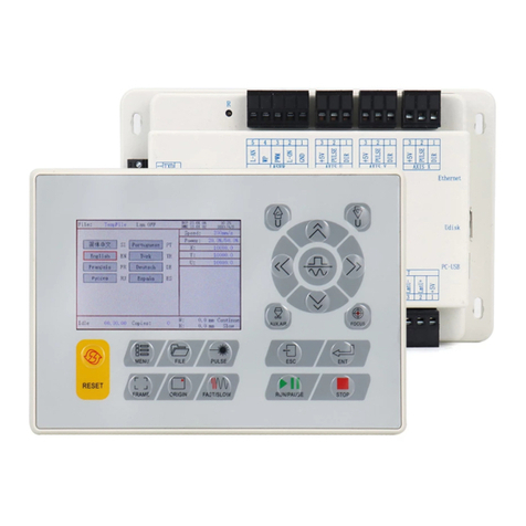
Simco-Ion’s IQ Power Control Station provides a power and communication hub
for IQ Power and IQ Easy devices.
The Control Station features a universal line voltage input and will operate on 100
to 240 VAC, 50/60 Hz. It can provide power & communication for up to ten
IQ Power or IQ Easy static neutralizing devices. The Control Station also allows
Warning / Fault relay output connections, a Standby (STBY) input connector,
Ethernet and a USB connector.
The display on the Control Station is a full color, backlit LCD with integrated touch
screen. This interface allows monitoring and control of the IQ Power / IQ Easy
static eliminating system. The control features four different operating modes for
static eliminators; fixed, manual, Auto-Tune and CLFB (Closed Loop Feed Back).
Along with providing a convenient user interface, the Control Station allows for data
logging of the system.
The Control Station also features a Fieldbus Interface that provides for a
factory installed module that provides network connectivity. A variety of fieldbus
communication protocols are available, such as EtherNet/IP, PROFIBUS DP-V1,
PROFINET IO, Modbus RTU, Modbus TCP, DeviceNet and ControlNet by use
of an HMS Industrial Network Anybus Module.
IQ Power system components, such as the BPS, HL, and HLC use 8-conductor
modular cable and RJ-45 connectors for connection. IQ Power devices are typically
supplied with a 7 foot modular cable assembly. Components, such as the IQ Easy
Static Bar, IQ Easy Sensor Bar, and IQ Power MPS use 5-conductor cable with
M12 connectors for connection. Cables are available by calling Simco-Ion customer
service (800) 203-3419 (refer to Section 8, Parts and Accessories).

4
IQ POWER CONTROL STATION
WITH SENSOR TECHNOLOGY
5201263 Rev D
3. SPECIFICATIONS
Input Power 100-240V~ 50/60 Hz, 4A max (IEC 320 inlet)
Output Voltage 24 VDC (all IQ Power and IQ Easy connectors)
Device Port USB-A
Network Port Ethernet
Interface 10.2”ColorTFT LCD (backlit) with resistive touch screen
Operating Temp 39°C [102°F] max
Mounting Slots M6 or M5 [1/4”or #10] hardware (not included)
Enclosure Steel, blue epoxy powder coated
Dimensions 197L x 314W x 118H mm [7.75”L x 12.38”W x 4.65”H]
Weight 5.2 kg [11.4 lb]

5
IQ POWER CONTROL STATION
WITH SENSOR TECHNOLOGY
5201263 Rev D
4. INSTALLATION
NOTE – DO NOT USE standard Ethernet cables with IQ Power systems.
Avoid permanent equipment damage by using only Simco-Ion modular
cables. (Refer to Section 8, Parts and Accessories).
Figure 1. IQ Power Crossover Modular Cable (black)
Mounting
Install the Control Station at a convenient place that keeps total overall cable length
to a minimum.
The black modular cable supplied with unit to connect the Control Station to an IQ
Power device is 2.13 meter [7 foot] long, however longer cables (not supplied) are
available. Cables must be 8-conductor modular cables with RJ-45 connectors wired
“crossover” (reference color: black, Figure 1).
Cables used to connect IQ Easy Static Bar, Sensor Bar or IQ Power MPS are
available in a variety of standard lengths with straight M12 connectors at the Control
Station end and with a straight or right angle M12 connector at the device end.
Secure Control Station to the mounting surface using M6 or M5 [1/4” or #10]
hardware (not included).
A small stylus and self-adhesive mounting clip are included with the unit. Remove
the protective backing from the mounting clip and place it adjacent to, or on the
side of, the Control Station.

6
IQ POWER CONTROL STATION
WITH SENSOR TECHNOLOGY
5201263 Rev D
Display Configuration
CAUTION – Electrical Shock Hazard
Disconnect input power before opening unit. Do not connect input power
with unit open.
ATTENTION – Risque De Choc Électrique
Mettre hors tension avant l’ouverture de l’unité. Ne rebranchez pas avec
l’unité ouverte.
The Control Station may be reconfigured, placing the connector panel at the “top”
of the unit, if desired (factory configuration is with the connector panel at the
“bottom” of the unit). To reconfigure the unit, remove line cord from power inlet
connector. Remove screws from sides of unit. Lift cover off of unit. The interface
display rests on brackets built into the case. Carefully lift the interface display just
off unit and rotate 180˚, use care not to stress the electrical cables. Place interface
display back onto brackets built into case. Check that no cables are pinched by
looking through gaps at top and bottom of unit. Move cables if necessary. Replace
cover and secure with screws on sides.
System Configuration
The Control Station and related IQ Power / IQ Easy devices can be configured in
a variety of ways. The range of static neutralizing and sensing equipment available
allow for flexibility in meeting application requirements. When a static neutralizing
device is paired with a static sensing device, the pair is considered a single device.
The following figures each illustrate a fundamental configuration with specific
equipment. Fundamental configurations may be combined on a system to meet the
particular needs of the application.

7
IQ POWER CONTROL STATION
WITH SENSOR TECHNOLOGY
5201263 Rev D
Figure 2. IQ Power Connections (Control Station 1 thru 10 to BPS Power Supply and Bar)

8
IQ POWER CONTROL STATION
WITH SENSOR TECHNOLOGY
5201263 Rev D
Figure 3. IQ Power Connections (Control Station to MPS Power Supply)

9
IQ POWER CONTROL STATION
WITH SENSOR TECHNOLOGY
5201263 Rev D
Figure 4. IQ Power Connections (Control Station to BPS Power Supply with Options)

10
IQ POWER CONTROL STATION
WITH SENSOR TECHNOLOGY
5201263 Rev D
Figure 5. IQ Power Connections (Control Station to IQ Easy Sensor and Neutralizing Bar)

11
IQ POWER CONTROL STATION
WITH SENSOR TECHNOLOGY
5201263 Rev D
Figure 6. IQ Power Connections (Control Station to HL Sensor Interface)

12
IQ POWER CONTROL STATION
WITH SENSOR TECHNOLOGY
5201263 Rev D
to PS COMM 2
Connection
to PS COMM 1
Connection
Comm / Data Cable Construction
1Crossover Wired Reference color black
Ground
Lead
Comm / Power (black)
1
IQ Power
HL Power Supply
NOTE:
HL Power Supply
and HL Sensor Interface
both report to CS under
HL Power Supply address.
Intrinsic Safety Barriers
see Control Drawing
5150010
IQ Power HL
Sensor Interface
to SI COMM 1
Connection
IQ Power HL Power Supply
with IQ Power HL Sensor
typically used for
CLFB mode
Comm / Power (black)
1
to Sensor Port
Connection
to
HV1 or HV2
IQ Power HL Sensor Cable
(part of Sensor)
IQ Power
HL Sensor
Ground Jumper
Machine Frame Ground
To Clean, Dry
Compressed Air Source
if Purge Required
Conduit and
Conduit Seals
see Control Drawing
5150003
Ground Jumper
Machine Frame Ground
Grounding Clamp
IQ Power HL Static Bar
Web Direction of Travel
Minimum 12" Downstream
IQ Power Control Station
to IQ Power device
to IQ Easy device
to CS 1 thru 10
POWER & COMM
DO NOT USE standard Ethernet cables.
See Section 8 Parts and Accessories for available cable lengths and part numbers.
Figure 7. IQ Power Connections (Control Station to HL Power Supply with Sensor Interface)

13
IQ POWER CONTROL STATION
WITH SENSOR TECHNOLOGY
5201263 Rev D
WARNING:
Substitution of components may
impair intrinsic safety.
AVERTISSEMENT:
La substitution de composants peut
compremettre la securite intrinseque.
Referto
Manual
IQ Power HL Static Bar
IQ Power
HLC Power Supply
Comm / Data Cable Construction
1Crossover Wired Reference color black
DO NOT USE standard Ethernet cables
to POWER & COMM
Connection
Comm / Power (black)
1
Conduit and
Conduit Seals
see Control Drawing
5150004 or 5150005
to
HV1 or HV2
to PS COMM 1
Connection
Grounding
Clamp Ground
Jumper
Machine
Frame
Ground
HV1 HV2
IQ Power
HLC Power Supply
(Interior View)
PS COMM 1
(2 Places)
to RDM COMM 2
Connection
to RDM COMM 1
Connection
Ground
Lead
with
IQ Power
RDM
Comm / Power (black)
1
IQ Power Control Station
to IQ Power device
to IQ Easy device
Figure 8. IQ Power Connections (Control Station to HLC Power Supply)

14
IQ POWER CONTROL STATION
WITH SENSOR TECHNOLOGY
5201263 Rev D
WARNING:
Substitution of components may
impair intrinsic safety.
AVERTISSEMENT:
La substitution de composants peut
compremettre la securite intrinseque.
Referto
Manual
IQ Power HL Static Bar
Web Direction of Travel
Minimum 12" Downstream
IQ Power
HLC Power Supply
Comm / Data Cable Construction
1Crossover Wired Reference color black
DO NOT USE standard Ethernet cables
to POWER & COMM
Connection
Comm / Power (black)
1
Intrinsic Safety Barriers
see Control Drawing
5150010
IQ Power HL
Sensor Interface
to SI COMM 1
Connections
IQ Power HLC Power Supply
& RDM with
IQ Power HL Sensor
typically used for
CLFB mode
Conduit and
Conduit Seals
see Control Drawing
5150004 or 5150005
to Sensor Port
Connection
IQ Power
HL Sensor
Ground Jumper
Machine Frame Ground
To Clean, Dry
Compressed Air Source
if Purge Required
Machine Frame Ground
to
HV1
or
HV2
to PS COMM 1
Connection
Comm / Power (black)
IQ Power HL Sensor Cable
(part of Sensor)
1
NOTE:
HLC Power Supply
and HL Sensor Interface
both report to CS under
HLC & RDM address.
Grounding
Clamp
Ground
Jumper
Machine
Frame
Ground
to RDM COMM 2
Connection
to RDM COMM 1
Connection
Ground
Lead
with
IQ Power
RDM
Comm / Power (black)
1
IQ Power Control Station
to IQ Power device
to IQ Easy device
Figure 9. IQ Power Connections (Control Station to HLC Power Supply with Sensor Interface)

15
IQ POWER CONTROL STATION
WITH SENSOR TECHNOLOGY
5201263 Rev D
Figure 10. IQ Power Connections (Control Station to Fantom Wide Blower)

16
IQ POWER CONTROL STATION
WITH SENSOR TECHNOLOGY
5201263 Rev D
Figure 11. IQ Power Connections (Control Station to Fantom with Options)

17
IQ POWER CONTROL STATION
WITH SENSOR TECHNOLOGY
5201263 Rev D
Electrical Connections
NOTE – If multiple IQ Power/IQ Easy devices are connected to the Control
Station, each static neutralizer must have a unique address / device number.
Addressing of devices takes place as the first step of the Set Up procedure.
NOTE – The maximum total number of devices plugged into “POWER &
COMM” 1 thru 10 and DEV1 thru DEV6 is 10 devices. A static neutralizer
is always considered one (1) device. When a Sensor Bar or HL Sensor
Interface is paired with a neutralizer, the pair is considered one (1) device. A
Sensor Bar or HL Sensor Interface that is not paired with a static neutralizer
is considered one (1) device. Exceeding 10 devices will cause communication
errors and system failure.
Figure 12. IQ Power Control Station Connectors
A. Connect the IQ Power BPS / HL Power Supplies
The Control Station can supply 24 VDC power for up to ten IQ Power BPS or HL
power supplies. Use the 2.13 meter [7 foot] black modular cable supplied with unit
or a longer cable (not supplied) is available. Cables for the Control Station must
be 8-conductor modular cables with RJ-45 connectors wired “crossover” (reference
color: black, Figure 1.).
When powered from the Control Station, the “Power” switch on the BPS / HL
power supply is not in-circuit, the BPS / HL will energize when the Control Station
power is switched on.
The modular cable plugs into either “PS COMM 1” connector on the BPS or HL
power supply.

18
IQ POWER CONTROL STATION
WITH SENSOR TECHNOLOGY
5201263 Rev D
The other end of the cable plugs into one of the ten connectors numbered 1 thru
10, labeled “POWER & COMM”.
CAUTION – Electrical Shock Hazard
Each power supply requires its own ground lead connection to machine
frame ground.
ATTENTION – Risque De Choc Électrique
Chaque bloc d’alimentation nécessite sa propre connexion de mise à la terre
au châssis de la machine.
If an IQ Easy Sensor Bar is to be used with the BPS (typically in CLFB - Closed
Loop Feed Back) it is required the sensor bar be plugged into connector “PS
COMM 2” of that BPS power supply. This will automatically associate (pair) the
sensor bar with the BPS for CLFB mode.
If an IQ Power HL Sensor is to be used with the HL power supply (typically in
CLFB – Closed Loop Feed Back) it is required the sensor interface (from either
“SI COMM 1” connector) be plugged into connector “PS COMM 2” of that HL
power supply. This will automatically associate (pair) the sensors connected to the
HL power supply for CLFB mode.
See diagram for Control Station to Power Supply with Options Connections.
Modular cables should not be run parallel with the static bar high voltage cable.
Route modular cables clear of moving machine parts and protect them from
abrasion. Secure using nylon wire ties (not included). Do not over-tighten wire tie.
If there is an excess of modular cable, do not coil it in the vicinity of the static bar
high voltage cable. If possible, cut modular cable to length and re-terminate using
an RJ-45 connector installed with the same polarization as connector removed (note
orientation of rib / wire color sequence to modular connector).
B. Connect the IQ Power HLC Power Supplies
Cables for connection must be 8-conductor modular cable with RJ-45 connectors
wired “crossover” (reference color: black, Figure 1).
Plug one end of modular cable into one of the HLC Power Supply “PS COMM
1” jacks. Run cable through rigid metal conduit to either Control Station or Sensor
Interface (if used).
If the system is without Sensor Interface, plug other end of modular cable (from
HLC Power Supply) into one of the “POWER & COMM” jacks on the Control
Station.
If the system is with Sensor Interface, plug other end of modular cable (from
HLC power supply) into one of the connections labeled “SI COMM 1” on Sensor
Interface. The second modular cable plugs in to the other connector labeled “SI
COMM 1” on Sensor Interface and into one of the connectors labeled “POWER &
COMM” on the Control Station.
Other manuals for IQ Power
1
Table of contents
Popular Control System manuals by other brands

Kemper
Kemper KHS Logic Control System Installation and operating instructions
Roger
Roger MCT88M-IO installation manual

Laguna Tools
Laguna Tools CNC Swift Series manual

ETC
ETC Expression Show Control System manual
Midea
Midea V4 Plus S Series instruction manual

Autotrol
Autotrol 460i Operation and maintenance manual

